
Platform reference: Chinese source V2.7.0 (RK-CS-YF-094) lists 29/30/31/32/33/35, PX, RV, Sofia and MCU series and all kernel versions; this does not promise support on every ArmSoM board. Check the exact SoC, controller, port, BSP, kernel and TRM, especially Type-C power/roles. These are source examples, not ArmSoM hardware measurements. Only a Chinese PDF is available; all four languages retain its original images.
Caution: io directly writes registers; mode/power switching is risky and no hardware command was executed. Source ambiguities retained: some cat sys/… paths lack a leading slash; Host sections say Device; BER is written 10e-12; Device channel text says 11 inches while the screenshot says 5 inches; the 10 cm boundary is unspecified. Table 6 appears under Device but labels columns Host. Original addresses and constants were not guessed or changed.
Technical preface: USB2 covers High/Full/Low Speed, detailing High-Speed Signal Quality and Receiver Sensitivity. USB3 details Tx Compliance; Rx provides principles and precautions only. Rockchip controllers are independent: consult the TRM before selecting commands. Instruments include Agilent, Tektronix and LeCroy; follow the relevant manufacturer manual. All USB test commands refer to the port under test.
Other USB2 items include Packet Parameters, CHIRP Timing, Suspend/Resume/Reset Timing, Test J/K and SE0_NAK. Commands are organized by controller model and require some software knowledge; use Rockchip USB SQ Tool to find commands directly by schematic port names.
1. USB 2.0 Compliance Test
1.1 USB2 compliance test items
USB 2.0 Tx Signal Quality tests cover eye diagram, signal rate, end-of-packet width, crossover-voltage range (Low/Full Speed), JK/KJ jitter, consecutive jitter, monotonicity (High Speed), and rise/fall times. USB 2.0 Rx Receiver Sensitivity covers sensitivity, squelch threshold and minimum SYNC field.
1.2 USB2 Tx commands and tools
USB 2.0 Tx SQ sets the controller Test Control register to enter Test Packet Mode. The controller continuously sends a periodic test pattern; the oscilloscope analyzes its waveform for signal integrity. Rockchip Device ports enter this mode using commands or a test tool; Host ports require commands.
1.2.1 USB2 Device Tx commands and tools
USB 2.0 Device SQ commands are listed in Table 1 and can be entered over UART or ADB. Table 1: USB 2.0 Device SQ commands.
| Chip | DWC2_0 OTG 2.0 Device |
DWC3_0 OTG 2.0 device | DWC3_1 OTG 2.0 device |
|---|---|---|---|
| RK1808 | N.A | io -4 0xfd00c704 0x8c000a08 | N.A |
| RK1820 | N.A | io -4 0x102500c704 0x8c000a08 | io -4 0x102400c704 0x8c000a08 |
| RK2108 | io -4 0x41300804 0x40 | N.A | N.A |
| RK2116 | io -4 0x40040804 0x40 | N.A | N.A |
| RK2118 | io -4 0x50040804 0x40 | N.A | N.A |
| RK2206 | io -4 0x43040804 0x40 | N.A | N.A |
| RK29XX RK30XX RK31XX |
io -4 0x10180804 0x40 | N.A | N.A |
| RK3228 RK3229 |
io -4 0x30040804 0x40 | N.A | N.A |
| RK3288 RK3228H RK3328 RK3368 |
io -4 0xff580804 0x40 | N.A | N.A |
| RK3308 RK3308B-S RK3308H-S |
io -4 0xff400804 0x40 | N.A | N.A |
| RK3326 RK3326S PX30 PX30S |
io -4 0xff300804 0x40 | N.A | N.A |
| RV1103 RV1106 |
N.A | io -4 0xffb0c704 0x8c000a08 | N.A |
| RV1103B | N.A | io -4 0x20b0c704 0x8c000a08 | N.A |
| RV1108 | io -4 0x30180804 0x40 | N.A | N.A |
| RV1126 RV1109 |
N.A | io -4 0xffd0c704 0x8c000a08 | N.A |
| RV1126B | N.A | io -4 0x2150c704 0x8c000a08 | N.A |
| SOFIA-3GR | io -4 0xe2100804 0x40 | N.A | N.A |
| RK3366 | io -4 0xff4c0804 0x40 | io -4 0xff50c704 0x8c000a08 | N.A |
| RK3399 | N.A | io -4 0xfe80c704 0x8c000a08 | io -4 0xfe90c704 0x8c000a08 |
| RK3506 | io -4 0xff740804 0x40 | N.A | N.A |
| RK3528 | N.A | io -4 0xfe50c704 0x8c000a08 | N.A |
| RK3538 | N.A | io -4 0xfc00c704 0x8c000a08 | N.A |
| RK3562 | N.A | io -4 0xfe50c704 0x8c000a08 | N.A |
| RK3576 | N.A | io -4 0x2300c704 0x8c000a08 | io -4 0x2340c704 0x8c000a08 |
| RK3566 RK3568 |
N.A | io -4 0xfcc0c704 0x8c000a08 | N.A |
| RK625 | io -4 0x40180804 0x40 | N.A | N.A |
| RK3588 RK3588S |
N.A | io -4 0xfc00c704 0x8c000a08 | io -4 0xfc40c704 0x8c000a08 |
RK3506 OTG1 Device command: io -4 0xff780804 0x40. Alternatively, use the USB-IF USB HSET tool: USBHSET for EHCI or USBHSET for XHCI. Downloads:
- EHCI 32-bit: https://www.usb.org/document-library/usbhset-ehci-32-bit
- EHCI 64-bit: https://www.usb.org/document-library/usbhset-ehci-64-bit
- xHCI 32-bit: https://www.usb.org/document-library/xhsett-x32
- xHCI 64-bit: https://www.usb.org/document-library/xhsett-x64e (source URL)
Basic procedure:
-
Connect the Device port under test to the PC with a USB cable.
-
Open the tool, select Device, then click TEST (Figure 1).
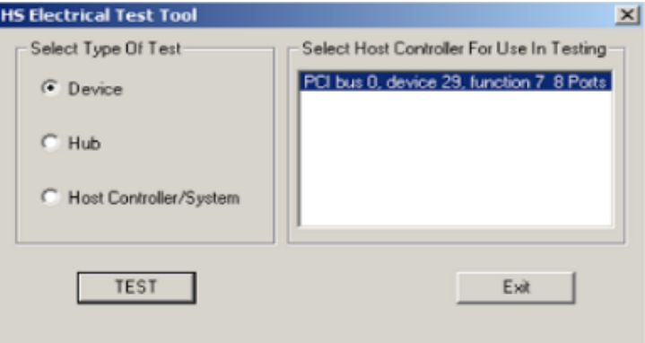
Figure 1. Select the test type.
- Select the target device and TEST PACKET, then EXECUTE (Figure 2). The controller enters Test Packet Mode and sends periodic packets with the waveform shown in Figure 3.
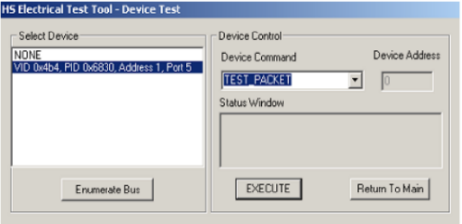
Figure 2. Select device and test command.
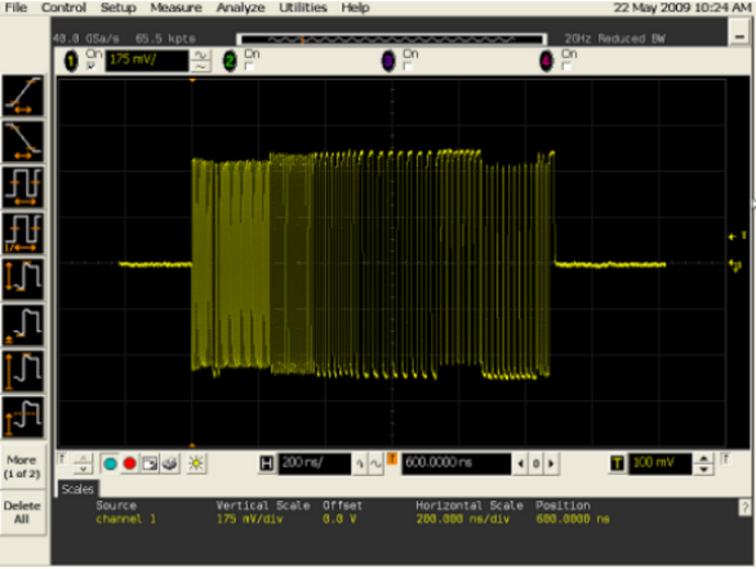
Figure 3. Test waveform.
1.2.2 USB2 Host Tx commands
USB 2.0 Host SQ requires commands; no dedicated test tool is provided. Enter the commands of Tables 2–4 over ADB or UART. Table 2: USB 2.0 Host SQ commands (a).
| Chip | DWC2_0 OTG Host 2.0 | DWC2_1 Host 2.0 | EHCI_0 Host 2.0 |
|---|---|---|---|
| RK1808 | N.A | N.A | io -4 0xffd80054 0x40000 |
| RK2116 | io -4 0x40040440 0x8000 | N.A | N.A |
| RK2118 | io -4 0x50040440 0x8000 | N.A | N.A |
| RK2206 | io -4 0x43040440 0x8000 | N.A | N.A |
| RK29XX RK30XX RK3188 |
io -4 0x10180440 0x8000 | io -4 0x101c0440 0x8000 | N.A |
| RK312X | io -4 0x10180440 0x8000 | io -4 0x101c0440 0x8000 | io -4 0x101c0054 0x40000 |
| RK3228 RK3229 |
io -4 0x30040440 0x8000 | N.A | io -4 0x30080054 0x40000 |
| RK3288 | io -4 0xff580440 0x8000 | io -4 0xff540440 0x8000 | io -4 0xff500054 0x40000 |
| RK3308 RK3308B-S RK3308H-S |
io -4 0xff400440 0x8000 | N.A | io -4 0xff440054 0x40000 |
| RK3326 RK3326S |
io -4 0xff300440 0x8000 | N.A | N.A |
| PX30 PX30S |
io -4 0xff300440 0x8000 | N.A | io -4 0xff340054 0x40000 |
| RK3228H RK3328 |
io -4 0xff580440 0x8000 | N.A | io -4 0xff5c0054 0x40000 |
| RK3366 | io -4 0xff4c0440 0x8000 | N.A | io -4 0xff480054 0x40000 |
| RK3368 | io -4 0xff580440 0x8000 | N.A | io -4 0xff500054 0x40000 |
| RV1108 | io -4 0x30180440 0x8000 | N.A | io -4 0x30140054 0x40000 |
| RV1126 RV1109 |
N.A | N.A | io -4 0xffe00054 0x40000 |
| RV1126B | N.A | N.A | io -4 0x21480054 0x40000 |
| SOFIA-3GR | io -4 0xe2100440 0x8000 | N.A | N.A |
| RK3399 | N.A | N.A | io -4 0xfe380054 0x40000 |
| RK3506 | io -4 0xff740440 0x8000 | io -4 0xff780440 0x8000 | N.A |
| RK3528 | N.A | N.A | io -4 0xff100054 0x40000 |
| RK3538 | N.A | N.A | io -4 0xfc100054 0x40000 |
| RK3562 | N.A | N.A | io -4 0xfed00054 0x40000 |
| RK3566 RK3568 |
N.A | N.A | io -4 0xfd800054 0x40000 |
| RK3588 RK3588S |
N.A | N.A | io -4 0xfc800054 0x40000 |
Table 3. USB 2.0 Host SQ commands (b).
| Chip | EHCI_1 Host 2.0 | EHCI_2 Host 2.0 | EHCI_HSIC Host 2.0 |
|---|---|---|---|
| RK3168 RK3188 |
N.A | N.A | io -4 0x10240054 0x40000 |
| RK3288 | N.A | N.A | io -4 0xff5c0054 0x40000 |
| RK3228 RK3229 |
io -4 0x300c0054 0x40000 | io -4 0x30100054 0x40000 | N.A |
| RK3368 | N.A | N.A | io -4 0xff5c0054 0x40000 |
| RK3399 | io -4 0xfe3c0054 0x40000 | N.A | io -4 0xfe340054 0x40000 |
| RK3566 RK3568 |
io -4 0xfd880054 0x40000 | N.A | N.A |
| RK3588 RK3588S |
io -4 0xfc880054 0x40000 | N.A | N.A |
Table 4. USB 2.0 Host SQ commands (c).
| Chip | DWC3_0 OTG Host 2.0 | DWC3_1 OTG Host 2.0 |
|---|---|---|
| RK1808 | io -4 0xfd000424 0x40000000 | N.A |
| RK1820 | io -4 0x1025000424 0x40000000 | io -4 0x1024000424 0x40000000 |
| RK3228H | io -4 0xff600424 0x40000000 | N.A |
| RK3366 | io -4 0xff500424 0x40000000 | N.A |
| RK3399 | io -4 0xfe800424 0x40000000 | io -4 0xfe900424 0x40000000 |
| RV1103 RV1106 |
io -4 0xffb00424 0x40000000 | N.A |
| RV1103B | io -4 0x20b00424 0x40000000 | N.A |
| RV1126 RV1109 |
io -4 0xffd00424 0x40000000 | N.A |
| RV1126B | io -4 0x21500424 0x40000000 | N.A |
| RK3528 | io -4 0xfe500424 0x40000000 | N.A |
| RK3538 | io -4 0xfc000424 0x40000000 | N.A |
| RK3562 | io -4 0xfe500424 0x40000000 | N.A |
| RK3566 RK3568 |
io -4 0xfcc00424 0x40000000 | io -4 0xfd000424 0x40000000 |
| RK3576 | io -4 0x23000424 0x40000000 | io -4 0x23400424 0x40000000 |
| RK3588 RK3588S |
io -4 0xfc000424 0x40000000 | io -4 0xfc400424 0x40000000 |
1.3 USB2 Tx setup
Use an oscilloscope with USB test software, such as Agilent 9000/90000, Tektronix or LeCroy. This example uses Agilent 9000: MSO9254A with N5416A USB2 software; 113xA active differential probe; E2678A differential probe head; E2649-66401 Device and E2649-66402 Host fixtures; USB2 cable. The cable must strictly meet USB2 specifications. Use Near End masks for cable lengths below 10 cm, Far End above 10 cm. Excessive cable length or impedance mismatch may cause Near End failures.
1.4 USB2 Tx procedure
- Build the setup. For Agilent, follow Agilent N5416A USB 2.0 Compliance Test Option and Agilent USB2.0 High Speed Device SQ Test. For Tektronix/LeCroy, obtain instructions from their official websites. Figure 4 shows an Agilent USB2 Device SQ setup.
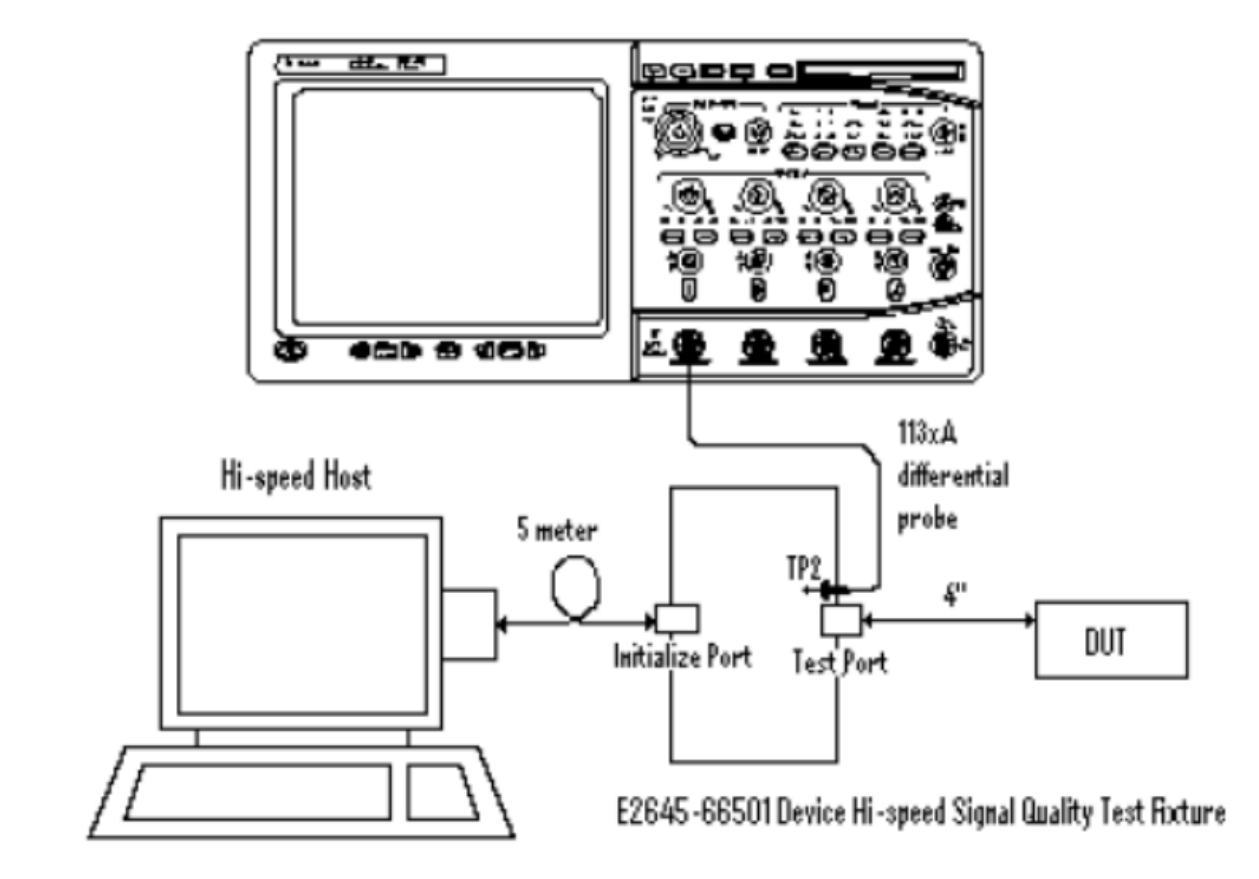
Figure 4. Agilent USB2 SQ setup.
- Enter Test Packet Mode. First confirm normal USB communication. For an OTG Device port, connect it to the PC through the fixture/cable and verify PC recognition, then use the Device commands or PC tool described earlier. For Host ports, the procedure differs between fixtures and oscilloscopes; Agilent and Tektronix examples follow.
2.1 Agilent test equipment
Connect the Host under test to one end of the fixture and a High-Speed device such as a flash drive to the other (Figure 5), then execute the test command.
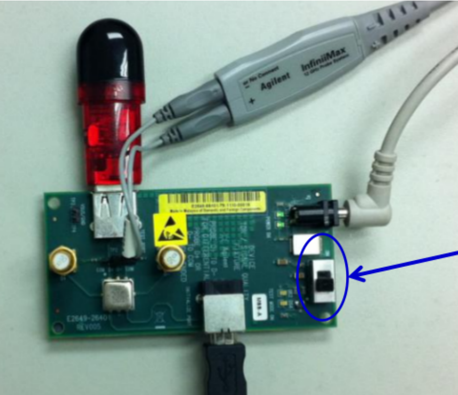
Figure 5. Agilent USB2 fixture connections.
2.2 Tektronix equipment: its fixture has only one port for the Host, so it cannot simultaneously connect another High-Speed device. Disconnect the fixture, attach a High-Speed device such as a flash drive to the Host, and execute the test command. Once test mode is entered, remove the device, connect the fixture and test. A High-Speed device is mandatory; do not use a Full-/Low-Speed mouse or keyboard.
- Analyze the waveform with automated USB software. In test mode, continuous periodic Test Packet Patterns are visible on the oscilloscope (Figure 6). Its software analyzes them and generates the complete test report.
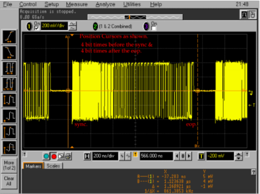
Figure 6. USB2 signal-quality analysis.
1.5 USB2 eye-diagram analysis
1.5.1 Standard USB2 eye diagram
USB2 uses Near End and Far End eye masks. For High-Speed SQ, cables shorter than 10 cm between port and fixture use Near End; longer than 10 cm use Far End. For reliable Rockchip USB2 quality, the source recommends the stricter Near End mask as a common reference. Figures 7/8 show standard eyes with each mask.
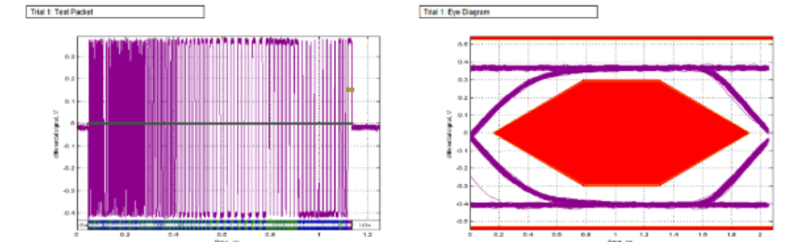
Figure 7. USB2 High-Speed Near End eye diagram.
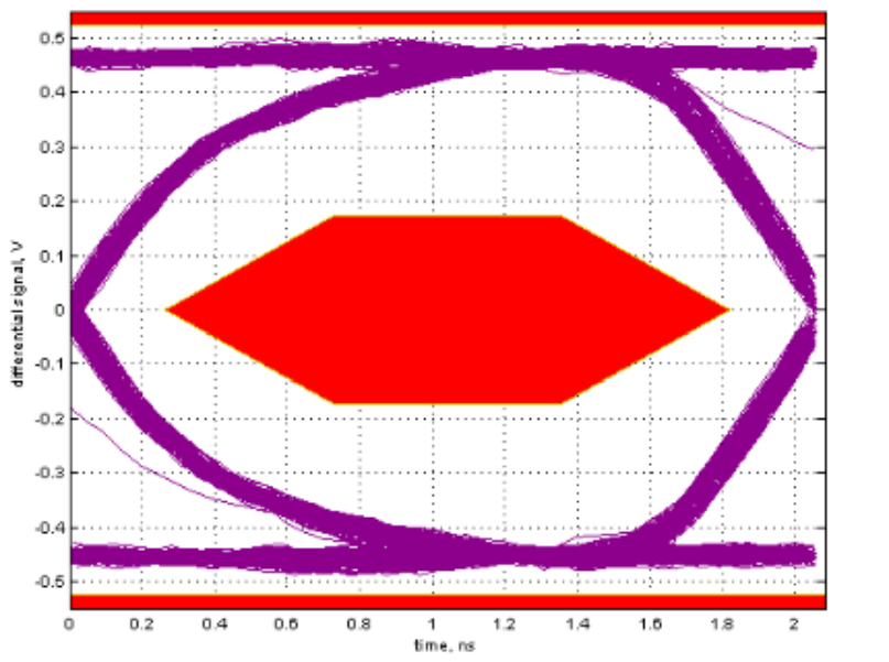
Figure 8. USB2 High-Speed Far End eye diagram. A standard eye has thin clear traces and a wide opening. Intersymbol interference distorts waveforms, prevents symbols from aligning and blurs/closes the eye. Added noise further blurs traces and narrows the opening. Eye opening thus indicates distortion and intersymbol-interference severity.
1.5.2 USB2 eye-diagram problems
-
No eye-test trigger detected: check fixture wiring and oscilloscope USB-software settings. Look for the periodic pattern of Figure 1-3. Its absence may mean the test command failed or is incorrect.
-
Severe distortion, such as amplitude error or collapse, usually indicates incorrect test procedure. In Figure 9 the amplitude is twice normal; with Agilent this generally means missing 50-ohm SMA terminations on D+/D-. The collapse in Figure 10 usually means the Agilent fixture switch is not ON.
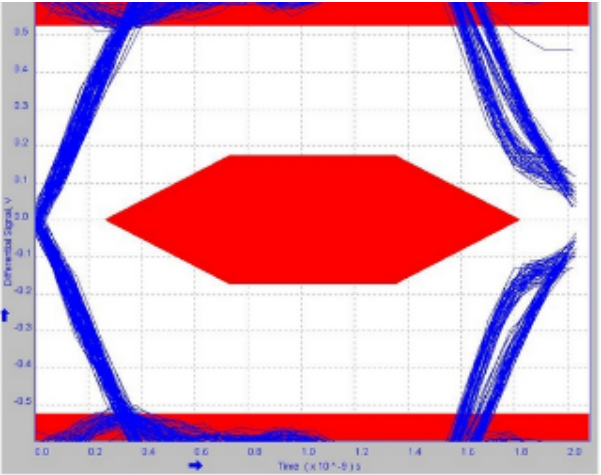
Figure 9. Eye amplitude distortion.
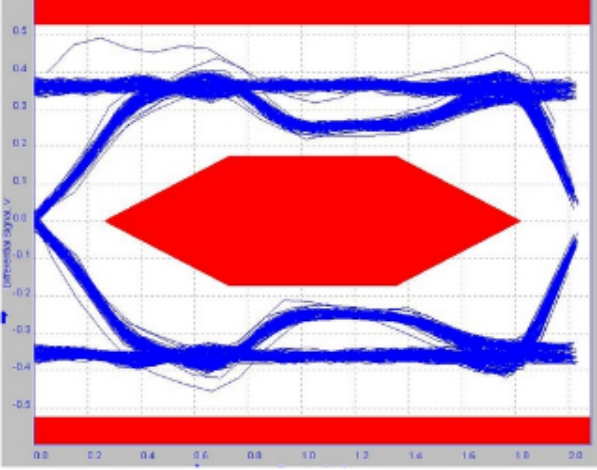
Figure 10. Eye signal collapse.
- Closed eye: Figure 11 crosses the mask. Check DP/DM for high-capacitance ESD devices or electronic switches; remove them for retesting if present. Adjust PHY drive strength and rise/fall edges in software with USB-driver engineering support.
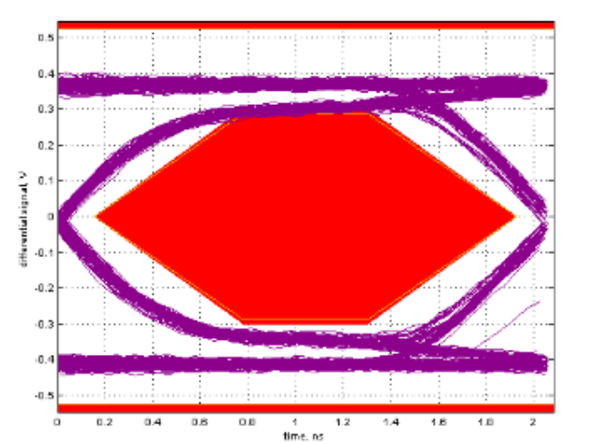
Figure 11. Closed USB eye.
- Blurred or densely streaked eye (Figure 12) indicates severe crosstalk, possibly impedance mismatch or noise. First check/remove high-capacitance ESD parts or switches on DP/DM and retest. Next check cable impedance or replace the cable. Finally inspect PCB routing, the USB 24 MHz clock source and PHY supply ripple.
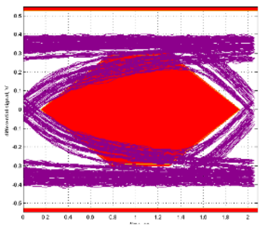
Figure 12. Blurred USB eye.
1.6 USB2 Rx Compliance Test
1.6.1 USB2 Receiver Sensitivity principle
USB 2.0 Electrical Compliance Test Specification 1.07 defines EL_16 Receiver Sensitivity @ Squelch, EL_17 Receiver Sensitivity and EL_18 Minimum SYNC Field. Put the DUT in SE0_NAK mode. A generator simulates a USB Host sending IN packets; correctly received packets cause DUT NAK responses. Vary IN amplitude and observe NAK to measure sensitivity. EL_16 sweeps high to low: response below 100 mV means excessive sensitivity and failure. EL_17 sweeps low to high: no stable response above 200 mV means inadequate sensitivity and failure. The original EL_17 limit was 150 mV, changed by ECN to 200 mV. Since the generator acts as Host, only Device/HUB upstream ports can be tested, not Host. NAK pattern: 32-bit sync (31 zeroes + one 1), then 8-bit NAK PID 10100101.
1.6.2 USB2 Rx commands
Table 5. USB2 Test SE0_NAK commands.
| Chip | USB 2.0 Test SE0_NAK command |
|---|---|
| RK1808 | io -4 0xfd00c704 0x8c000a06 |
| RK1820 | io -4 0x102500c704 0x8c000a06 |
| RK2108 | io -4 0x41300804 0x30 |
| RK2116 | io -4 0x40040804 0x30 |
| RK2206 | io -4 0x43040804 0x30 |
| RK29XX RK30XX RK31XX |
io -4 0x10180804 0x30 |
| RK3228 RK3229 |
io -4 0x30040804 0x30 |
| RK3288 RK3228H RK3328 RK3368 |
io -4 0xff580804 0x30 |
| RK3308 RK3308B-S RK3308H-S |
io -4 0xff400804 0x30 |
| RK3326 RK3326S PX30 PX30S |
io -4 0xff300804 0x30 |
| RV1103 RV1106 |
io -4 0xffb0c704 0x8c000a06 |
| RV1108 | io -4 0x30180804 0x30 |
| RV1126 RV1109 |
io -4 0xffd0c704 0x8c000a06 |
| RV1126B | io -4 0x2150c704 0x8c000a06 |
| RK3399 | io -4 0xfe80c704 0x8c000a06 |
| RK3566 RK3568 |
io -4 0xfcc0c704 0x8c000a06 |
| RK625 | io -4 0x40180804 0x30 |
| RK3588 RK3588S |
io -4 0xfc00c704 0x8c000a06 |
1.6.3 USB2 Rx procedure
For the standard procedure, see section 4.2.1 Upstream Port Receiver Sensitivity in USB 2.0 Electrical Compliance Test Specification 1.07. This example uses Tektronix equipment.
1.6.3.1 USB2 Rx precautions
Before issuing commands, connect DUT through the fixture to a PC Host so the Device PHY does not suspend. Enter Test SE0_NAK through UART. During EL_18, when the Tektronix generator switches from 32-bit to 12-bit SYNC, reverse its channel polarity.
1.6.3.2 USB2 Rx procedure
- Connect DUT through the Device Sensitivity fixture to the Tektronix generator and oscilloscope as in Figure 13.
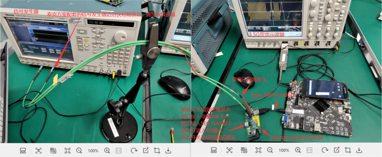
Figure 13. Tektronix USB2 Rx connections.
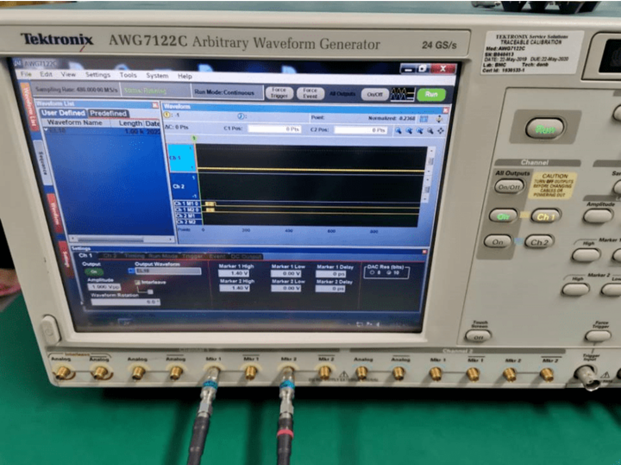
Figure 14. Tektronix signal generator.
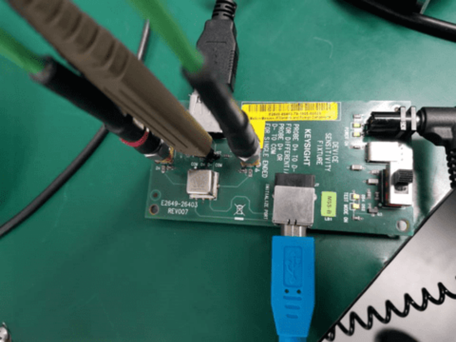
Figure 15. USB2 Rx Device Sensitivity fixture.
-
Set the fixture DIP switch ON and connect the fixture to the PC Host.
-
Select the Table 5 command and enter it through UART to put DUT in SE0_NAK mode.
-
Set the fixture DIP switch OFF.
-
Configure the Tektronix test pattern and perform EL_16, EL_17 and EL_18 in sequence.
1.6.3.3 USB2 Rx result analysis
Figure 16 shows the oscilloscope sampling the generator IN packet and DUT NAK response in real time and producing the illustrated test report.
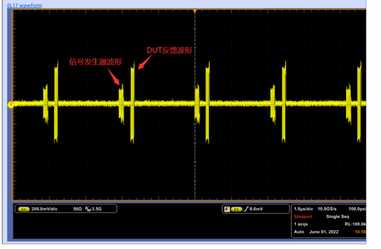
Figure 16. USB2 Rx signals.
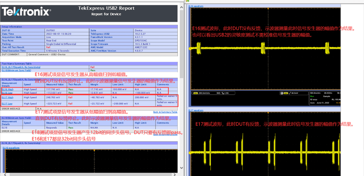
Figure 17. USB2 Rx report. If EL_16/EL_17 fails, try adjusting the USB2 PHY Squelch parameter; see Rockchip USB SQ Tool.
2. USB2 HUB SQ Test
HUB SQ covers upstream and downstream ports, but typical products only need user-facing downstream tests, which are described here. Common USB2 HUBs: FE1.1, FE1.1S, GL850, GL852, USX2064, HX2VL; HSIC HUBs: USB4604, GL850H. USB2 supports both methods below; HSIC only method 2. Method 1 uses Host test commands: identify the connected Host controller and its command in Tables 2–4, then follow the USB2 procedure for every downstream port. All ports use the same command/procedure. Method 2 compiles/runs a script: more complex, but universal for USB2 and HSIC HUBs.
-
Download and compile USB_HUB_Compliance_Test_Script from https://redmine.rockchip.com.cn/documents/113 .
-
Copy the compiled linux-eye executable to the system data directory, run
chmod 777 linux-eye, then launch linux-eye and enter test commands as prompted:
[root@hari LinuxEye]# ./linuxEye
LinuxEye - select one of the following hub for testing.
[ 0] 4-port Full-Speed hub at tier 2 of Bus 3
(VID: 0451, PID: 1446, Address: 3)
[ 1] 4-port High-Speed hub at tier 2 of Bus 1
(VID: 1A40, PID: 0101, Address: 15)
[ 2] 4-port High-Speed hub at tier 2 of Bus 1
(VID: 1A40, PID: 0101, Address: 10)
[ 3] 7-port High-Speed hub at tier 3 of Bus 1
(VID: 1A40, PID: 0201, Address: 50)
Please enter [0 ~ 3] to select a hub or 'q' to quit: 2 (表⽰共有4个HUB, 测试HUB[2])
[ 1] is connected to Low-Speed device
[ 2] is open
[ 3] is connected to High-Speed device
[ 4] is connected to Low-Speed device
Please enter [1 ~ 4] to select a port or 'q' to quit: 2 (表⽰测试HUB的第2个port)
LinuxEye - Start testing port 2 of device 10 on bus 1
Type 'q' to stop the test: q (退出测试脚本)
[root@hari LinuxEye]#
3. USB3 Compliance Test
USB3 has a dual-bus architecture, adding SuperSpeed to USB2. The SuperSpeed bus runs at 5 Gbps with ANSI 8b/10b encoding, full duplex and cable length up to 3 m. Figure 18 shows a typical architecture.
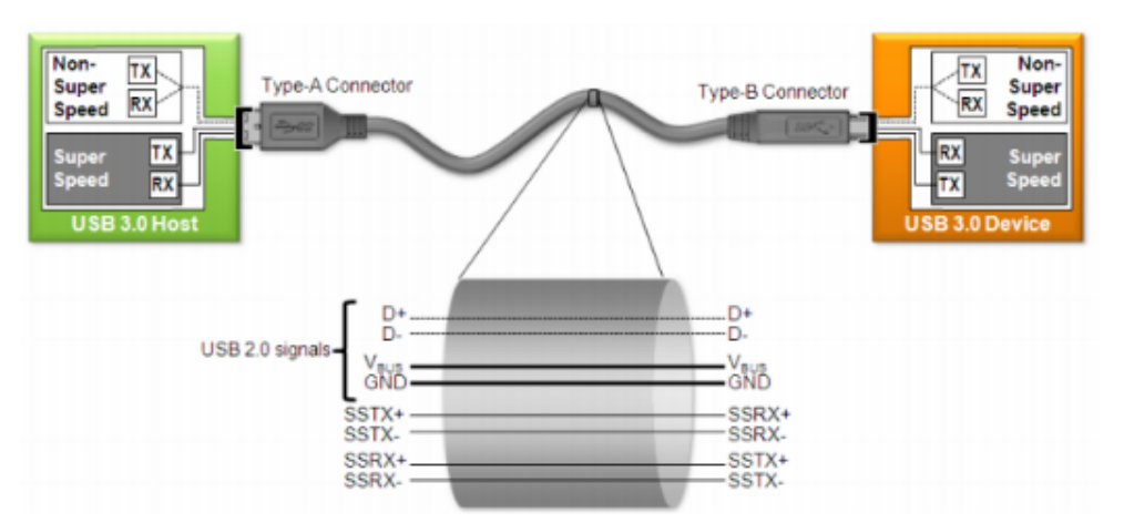
Figure 18. USB3 bus architecture.
3.1 Additional USB3 test specifications
Calibration/testing takes place at the end of the compliance channel, representing worst-case interconnection: Host 3 m cable + 5-inch trace; Device 3 m + 11-inch trace. Tx allows channel embedding using golden S-parameters. Calculate DJ/RJ/TJ at the source-specified 10e-12 BER and test compliance Pj at 10, 20 and 33 MHz. Postprocess with CTLE and analyze the equalized eye: 5 Gbps signals may close after long cable/PCB transmission; receiver CTLE compensates high-frequency loss, so oscilloscope software needs CTLE for realistic results. Device receiver eye calibration: 145 mVp-p; Host: 180 mVpp.
USB3 electrical testing comprises Tx, Rx Tolerance Compliance and cable/connector tests.
3.2 USB3 Tx Compliance Test
3.2.1 USB3 Tx requirements
The transmitter must emit specified patterns. A real-time scope analyzes the eye, amplitude, jitter, average data rate and rise/fall time. Unlike USB2, 5 Gbps USB3 with lower amplitude needs a scope above 12 GHz and low noise. The specified test point is the compliance-channel end, not a direct fixture measurement. The channel models Host 3 m cable + 5-inch PCB or Device 3 m + 11-inch PCB. USB3 provides S-parameter models. In practice, connect DUT directly through the fixture and embed the channel in the scope using S-parameters. TP1 in Figure 19 is the measurement point.

Figure 19. USB3 Tx test model.
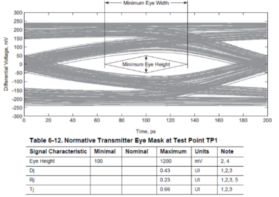
Figure 20. USB3 Tx eye requirements.
Editable transcription of the image table (referenced note texts are not supplied in the image):
| Signal characteristic | Minimum | Nominal | Maximum | Units | Note numbers |
|---|---|---|---|---|---|
| Eye height | 100 | 1200 | mV | 2, 4 | |
| Dj | 0.43 | UI | 1, 2, 3 | ||
| Rj | 0.23 | UI | 1, 2, 3, 5 | ||
| Tj | 0.66 | UI | 1, 2, 3 |
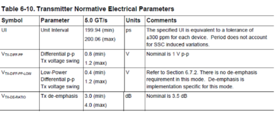
Figure 21. USB3 Tx electrical requirements.
Editable transcription of the image table (referenced note texts are not supplied in the image):
| Symbol | Parameter | 5.0 GT/s | Units | Comments |
|---|---|---|---|---|
| UI | Unit interval | 199.94 (min); 200.06 (max) | ps | UI corresponds to ±300 ppm tolerance per device; period excludes SSC-induced variation. |
| V_TX-DIFF-PP | Differential p-p Tx voltage swing | 0.8 (min); 1.2 (max) | V | Nominal 1 V p-p. |
| V_TX-DIFF-PP-LOW | Low-power differential p-p Tx voltage swing | 0.4 (min); 1.2 (max) | V | See section 6.7.2. No de-emphasis requirement in this mode; implementation-specific. |
| V_TX-DE-RATIO | Tx de-emphasis | 3.0 (min); 4.0 (max) | dB | Nominal 3.5 dB. |
3.2.2 USB3 Tx test items
LFPS (Near End); SSC (Near End); Tx (Near/Far End): eye diagram, Tj/Rj/Dj and amplitude.
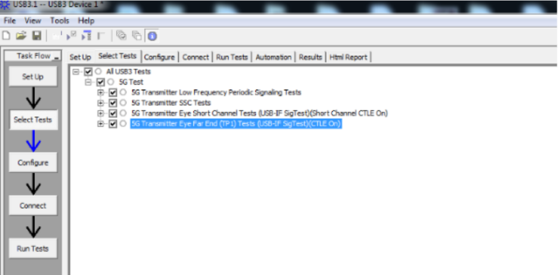
Figure 22. Agilent USB3 Tx options.
3.2.3 USB3 Tx test mode
USB3 requires Compliance Mode before Tx signal-integrity testing. After the first LFPS timeout during Polling, the controller leaves Polling.LFPS for Compliance Mode (Figure 23).
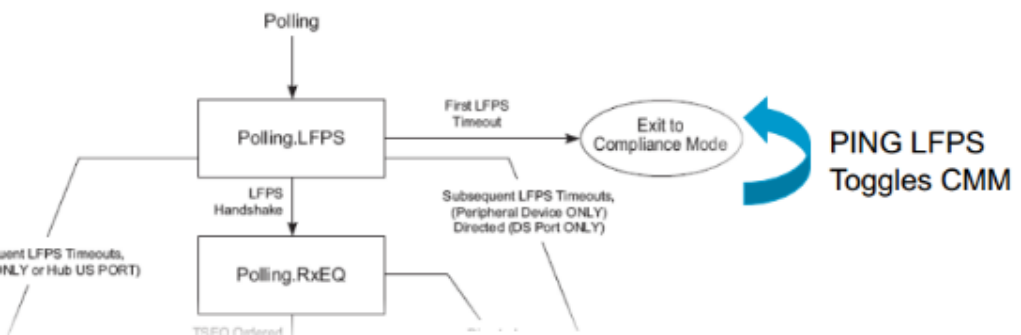
Figure 23. Entering USB3 Compliance Mode.
3.2.4 USB3 Tx setup
Agilent recommends its 90000-series scope (up to 13 GHz), U7243A automated compliance software and U7242A fixture for USB3 transmitter tests.
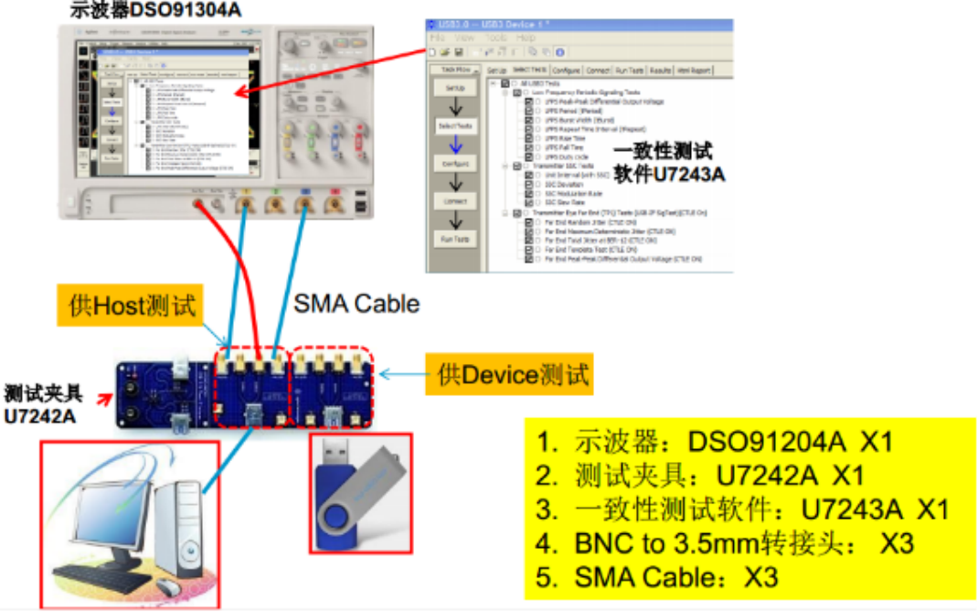
Figure 24. Agilent USB3 Tx setup.
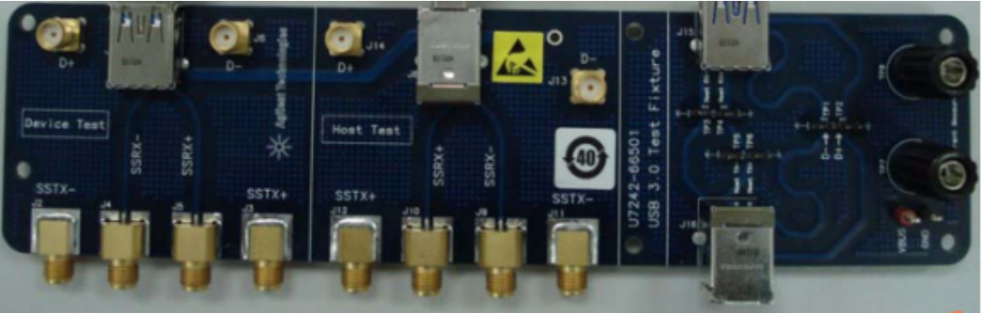
Figure 25. Agilent USB3 Tx U7242 fixture.
Agilent also offers N7015A for USB3.1 Gen1 Type-C (Figure 26), using the same software as U7242A. For USB3/3.1 Type-C signal-integrity testing, see Keysight N7015A-16A Type-C Test Kit.
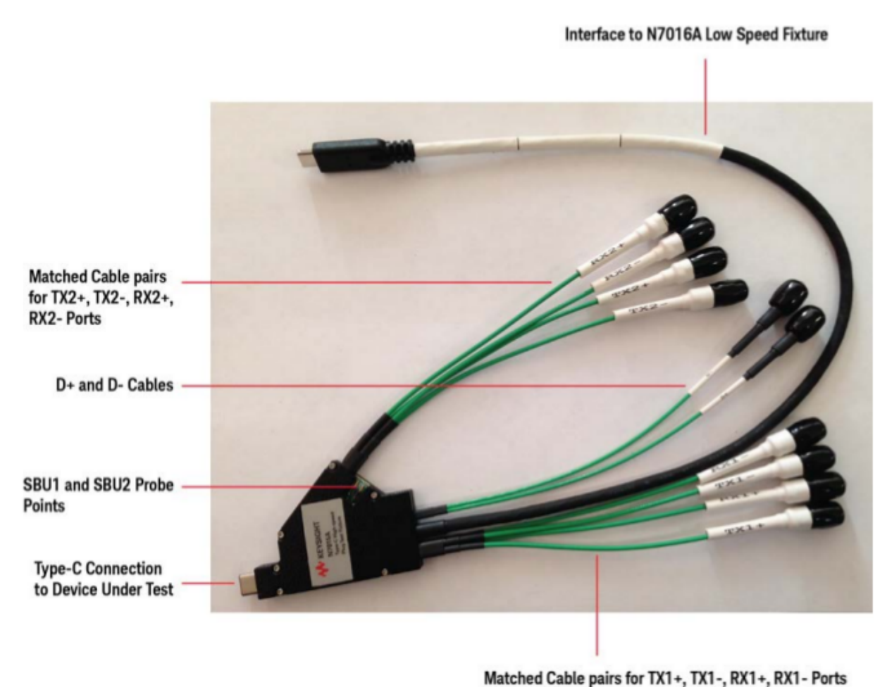
Figure 26. Agilent N7015A Type-C fixture. Tektronix setup is shown in Figure 27. USB-Tx on DPO/MSO70000 provides automated USB3 transmitter measurements: https://www.tek.com.cn/datasheet/usb3-transmitter-and-receiver-solutions-datasheet .
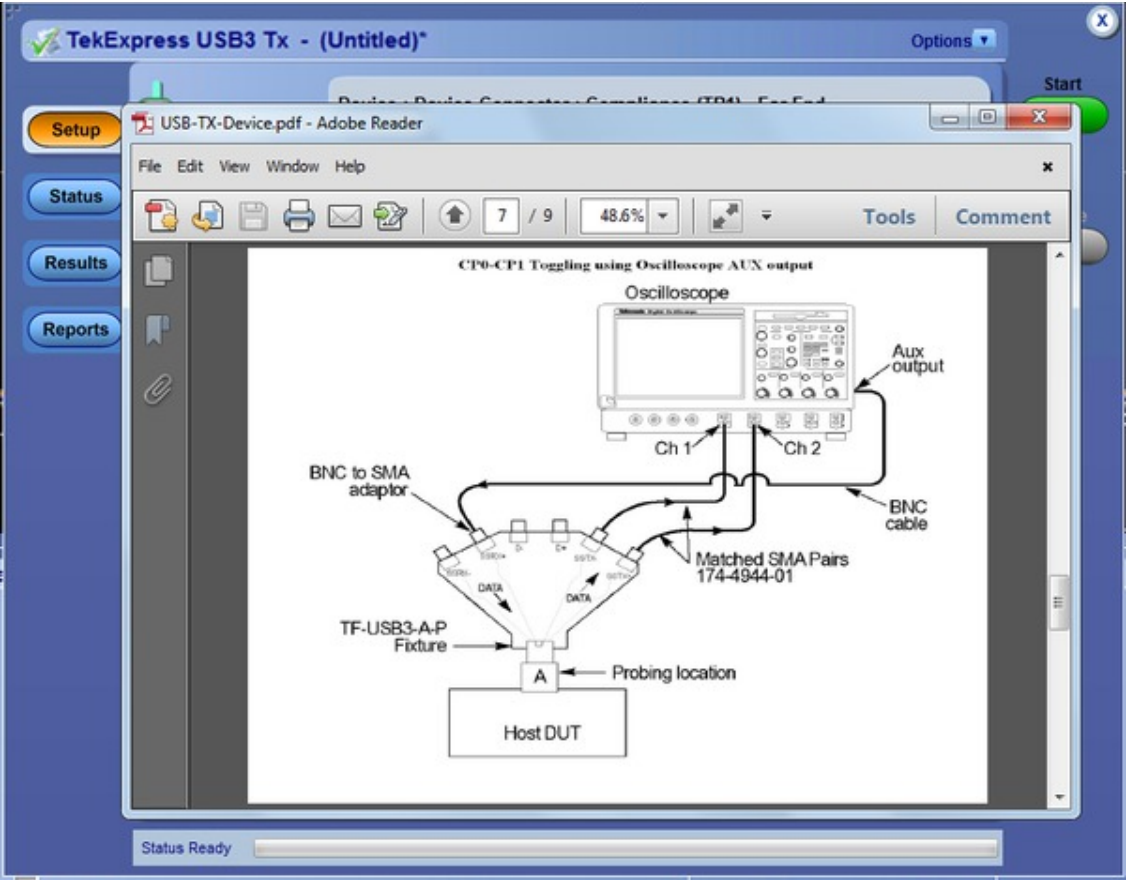
Figure 27. Tektronix USB3 Tx connections.
3.2.5 USB3 Device Tx commands
Some chips require a Device Tx command to trigger CP1. Enter it only when the scope asks for CP1; otherwise CP0/CP1 switching may be abnormal. Table 6 lists these commands.
| Chip | DWC3_0 OTG Host 3.0 | DWC3_1 OTG Host 3.0 |
|---|---|---|
| RK1808 | io -4 0xff384008 0xc | N.A |
| RK3228H RK3328 |
io -4 0xff478408 0xc | N.A |
Normally a Device enters Tx test mode without commands. In Table 6, RK1808/RK3228H/RK3328 need commands to enter CP1 manually; RK3399/RK3568/RK3588 need no Device command.
3.2.6 USB3 Device Tx procedure
The following Device Tx procedure uses an Agilent 90000-series DSO91204A and U7242A fixture. For Tektronix or LeCroy procedures, consult their official guides.
3.2.6.1 USB3 Device Tx precautions
Check Table 6 first. The Device normally enters Compliance Mode automatically after connection; if required, issue its command when the scope requests CP1. The Device must not source 5 V on VBUS. Supply VBUS through the U7242A USB power connection from the scope or PC.
3.2.6.2 USB3 Device Tx steps
Step 1: configure the automated test software.
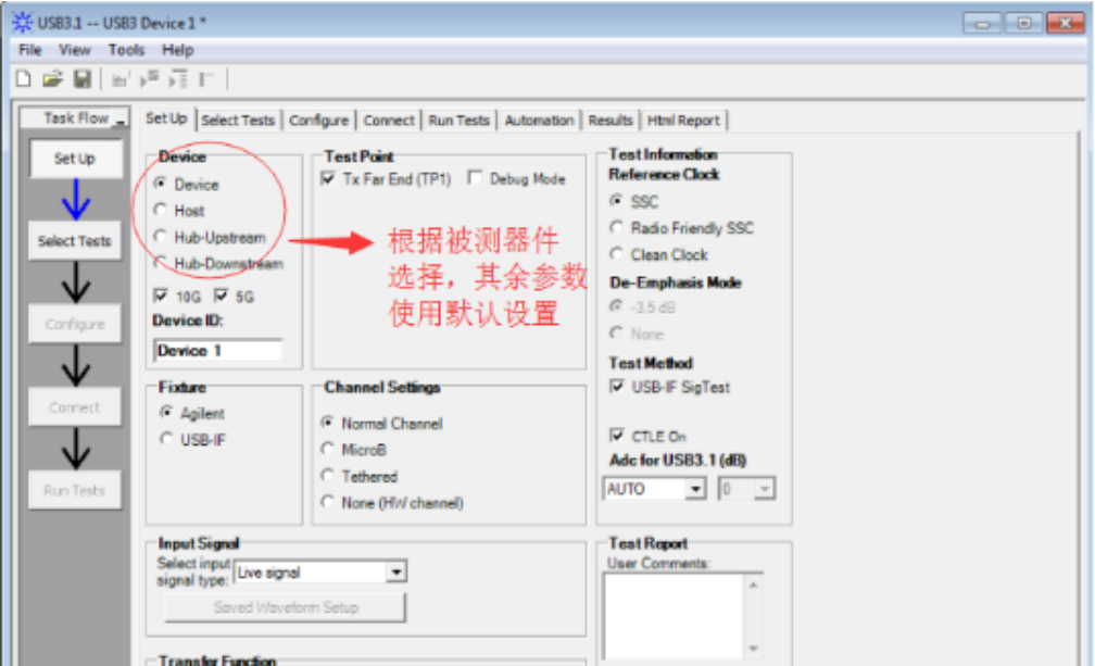
Figure 28 shows software V2.01. Newer V3.00.0001 has a different interface; configure the channel as shown below.
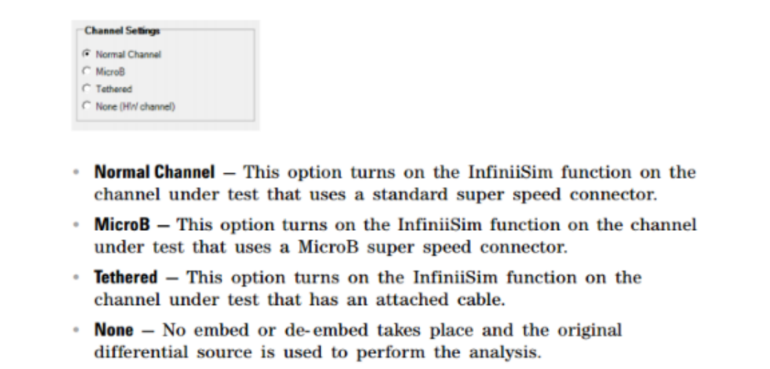
Figure 29. The Normal Channel default embeds a 3 m cable and 5-inch PCB model. Connect the fixture directly to the DUT. A physical cable longer than 10 cm may fail the Far End test; select None or use a cable shorter than 10 cm.
Step 2: select All USB3 Tests.
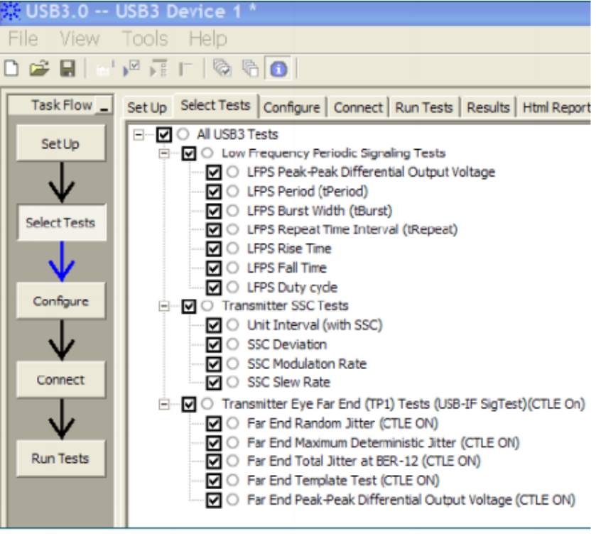
Figure 30. Selecting test items.
Step 3: set Automate Test Pattern Change to Auto; leave other settings at their defaults.
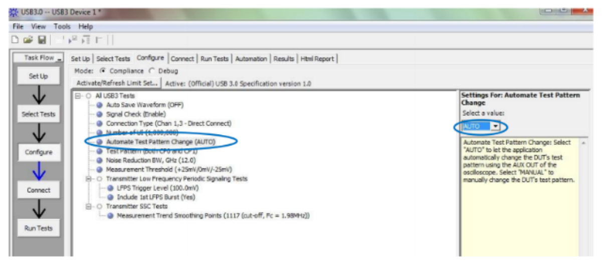
Figure 31. Test configuration.
Step 4: connect the scope, fixture and Device as prompted, including the 5 V VBUS supply.
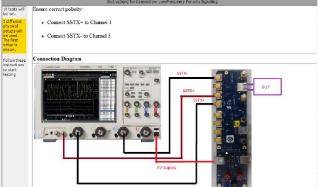
Figure 32. Device Tx connections.
Step 5: start the Tx test.
5.1 LFPS test instructions.
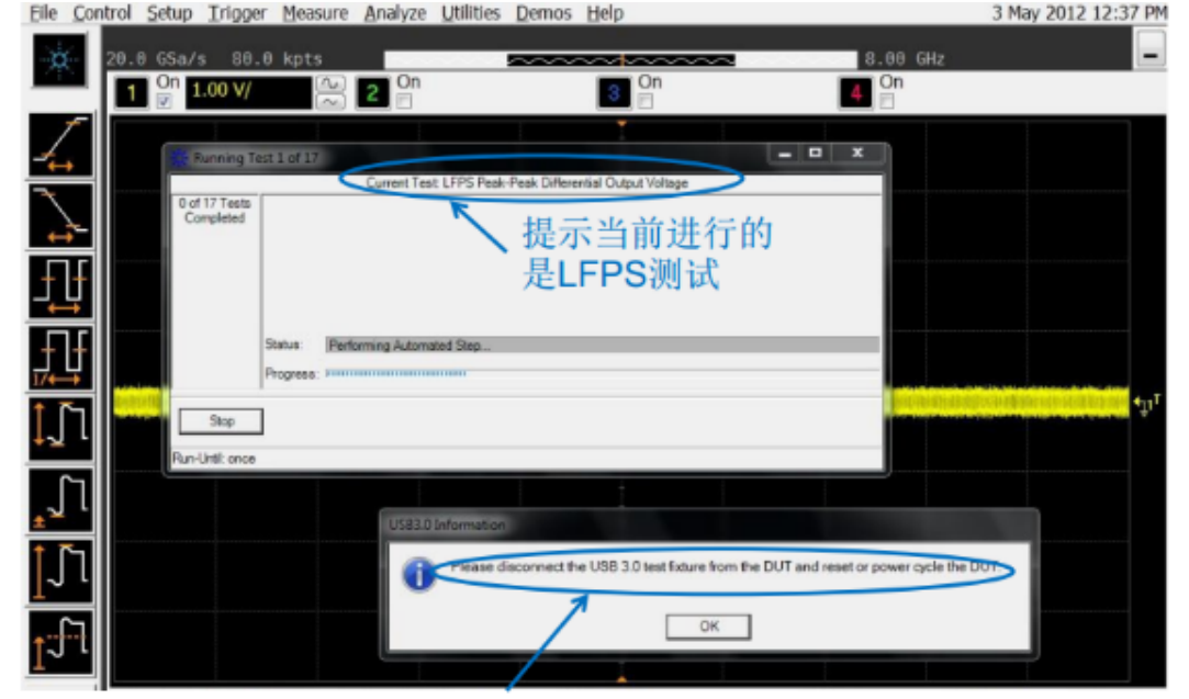
Figure 33. Before the LFPS test, disconnect the USB3 fixture from the DUT, click OK, then reconnect it.
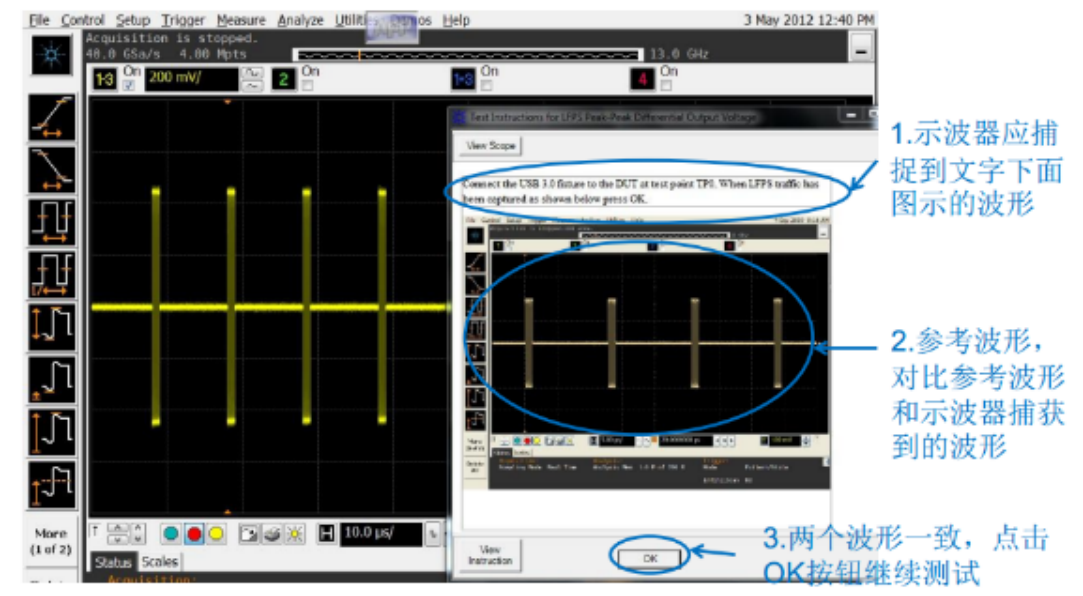
Figure 34. LFPS reference waveform.
5.2 After LFPS, change the connections as prompted for SSC testing.
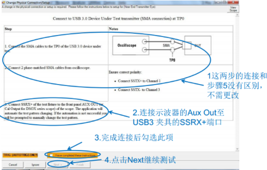
Figure 35. SSC connections.
5.3 After SSC, change the connections for eye-diagram and jitter tests.
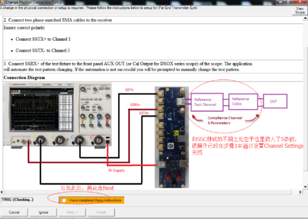
Figure 36. Eye-diagram and jitter connections.
5.4 Review the automatically generated test report.
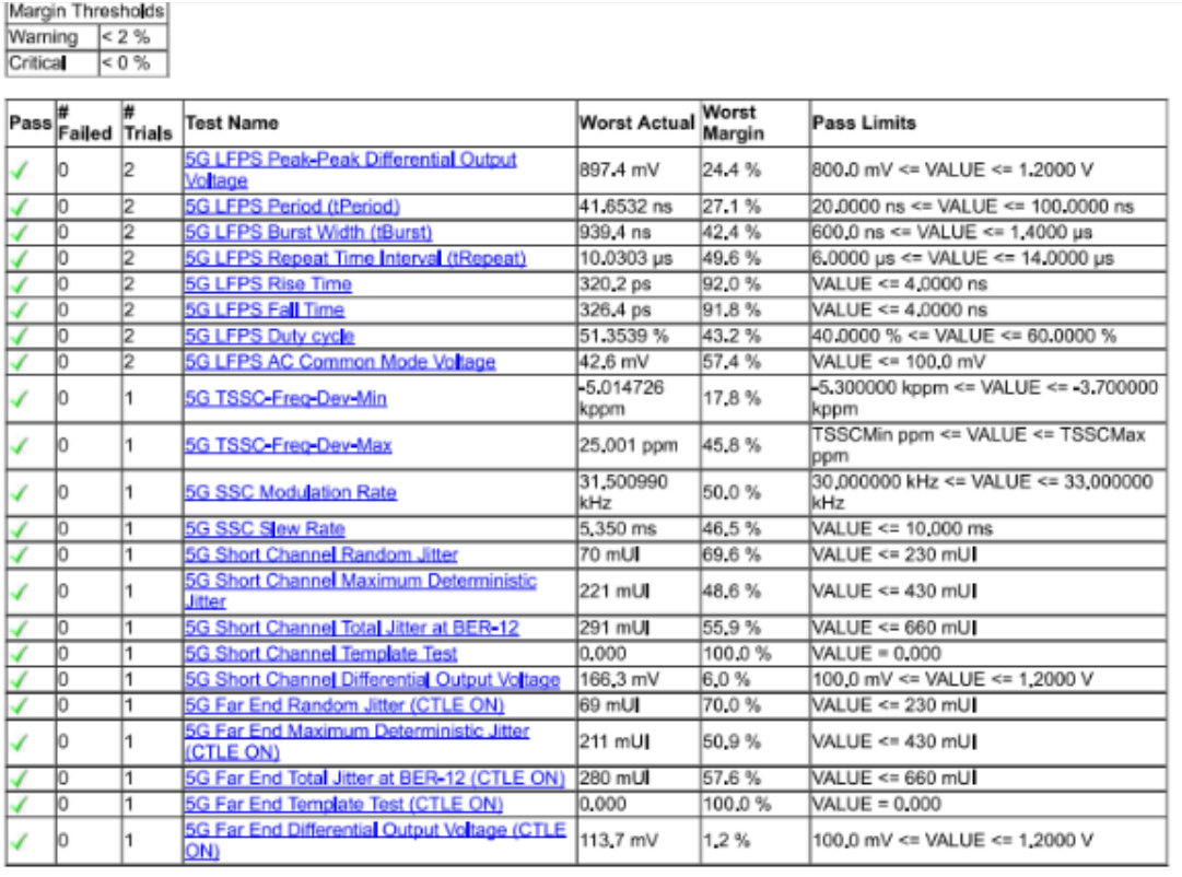
Figure 37. Test report.
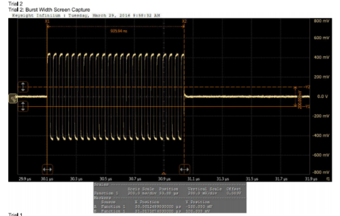
Figure 38. LFPS Burst Width.
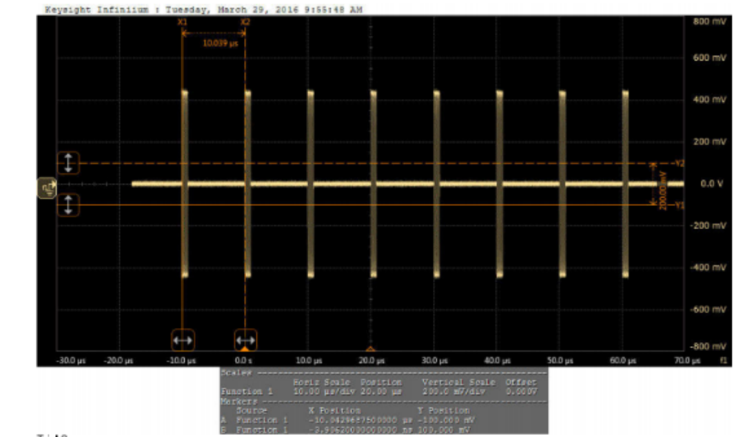
Figure 39. LFPS Repeat Time Interval.
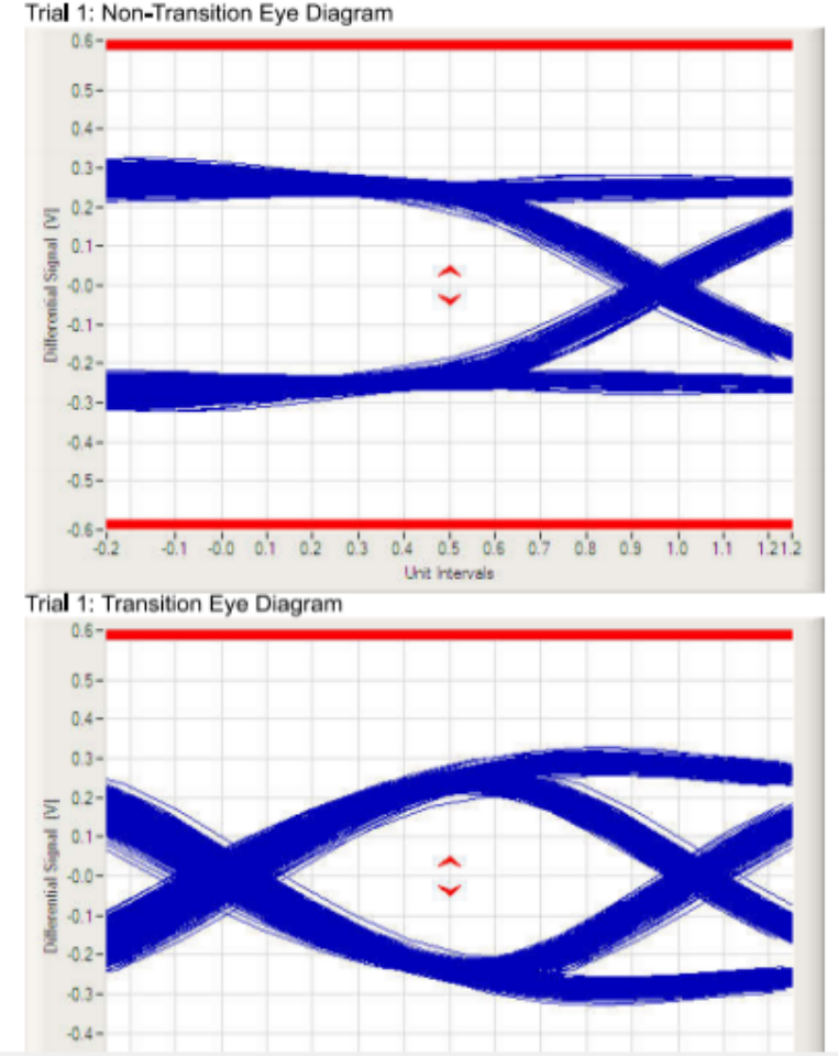
Figure 40. Short Channel Eye.
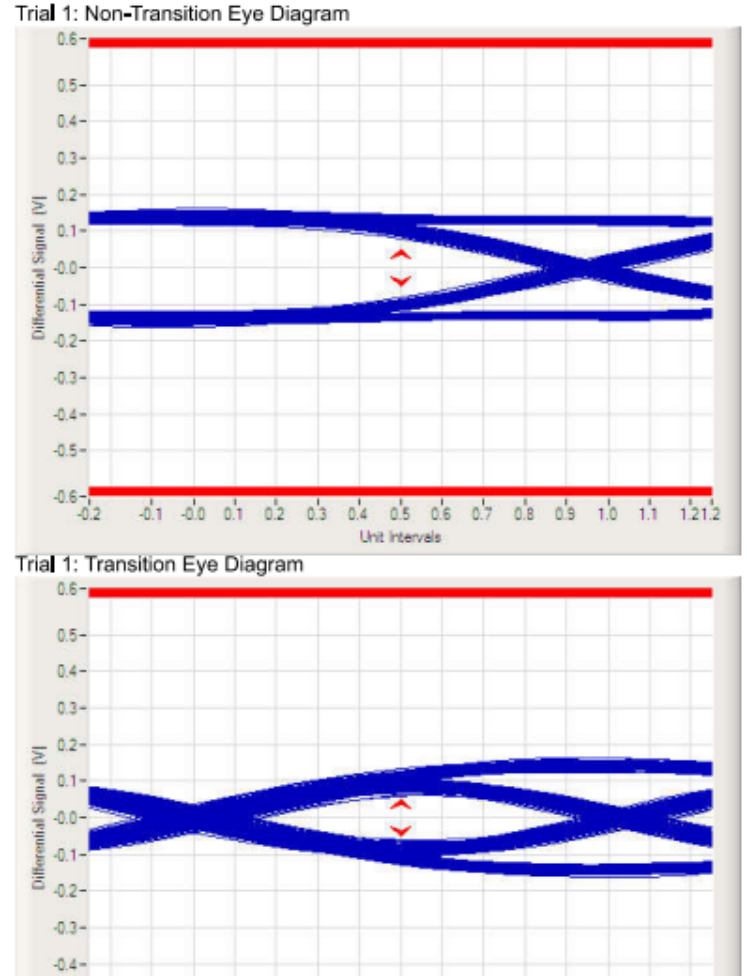
Figure 41. Far End Eye.
3.2.7 USB3 Host Tx commands
Table 7. USB3 Host Tx test commands.
| Chip | DWC3_0 OTG Host 3.0 | DWC3_1 OTG Host 3.0 | DWC3_2 Host 3.0 |
|---|---|---|---|
| RK1808 | io -4 0xff384008 0xc io -4 0xfd000430 0x0a010340 |
N.A | N.A |
| RK1820 | io -4 0x1025000430 0x0a010340 | N.A | N.A |
| RK3228H RK3328 |
io -4 0xff478408 0xc io -4 0xff600430 0x0a010340 |
N.A | N.A |
| RK3366 | io -4 0xff500430 0x0a010340 | N.A | N.A |
| RK3399 | io -4 0xfe800430 0x0a010340 | io -4 0xfe900430 0x0a010340 | N.A |
| RK3528 | io -4 0xfe500430 0x0a010340 | N.A | N.A |
| RK3562 | io -4 0xfe500430 0x0a010340 | N.A | N.A |
| RK3566 RK3568 |
io -4 0xfcc00430 0x0a010340 | io -4 0xfd000430 0x0a010340 | N.A |
| RK3576 | io -4 0x23000430 0x0a010340 | io -4 0x23400430 0x0a010340 | N.A |
| RK3588 RK3588S |
io -4 0xfc000430 0x0a010340 | io -4 0xfc400430 0x0a010340 | io -4 0xfcd00430 0x0a010340 |
| RV1126B | io -4 0x21500430 0x0a010340 | N.A | N.A |
RK1808/RK3228H/RK3328 have two commands; the first writes 0xc to trigger CP1 manually. Normally execute both together. If CP0/CP1 switching fails, first only write 0x0a010340, then write 0xc when CP1 is requested. The io commands apply across chips and kernels. For RK3399 Linux 3.10/4.4 Type-C kernel nodes, see section 3.4.2.
3.2.8 USB3 Host Tx procedure
The source describes the following as an Agilent 90000-series DSO91204A/U7242A Device Tx procedure, although it appears in the Host section. For Tektronix or LeCroy, consult their official guides.
3.2.8.1 USB3 Host Tx precautions
First connect a USB3 disk and verify SuperSpeed in the log, then remove it. Omitting this step may make RK3399 Type-A testing fail. Execute the Table 7 command before testing. The Host supplies 5 V VBUS; the fixture must not supply it, opposite to Device testing. Command timing differs between Type-A and Type-C.
3.2.8.2 USB3 Host Tx steps
Step 1: configure the software as for Device testing.
Step 2: connect fixture and scope, but do not connect the Host yet.
Step 3: at LFPS testing, the scope asks to disconnect the fixture from the Host.
Step 4: find the command for the chip and port in Table 7.
Step 5: for Type-A, issue the command before connecting; for Type-C, connect, wait 2–3 s for Host mode, then issue the command.
Step 6: connect fixture and Host; the test mode starts automatically.
Step 7: follow the remaining scope prompts to complete all tests.
3.2.9 Checking USB3 Tx Compliance mode
Device Tx query: cat /sys/kernel/debug/usb/xxxx/link_state, replacing xxxx with the tested USB controller node. Compliance means Device Tx mode. For Host Tx on Linux 4.19 and earlier, read xHCI PORTSC with io: bits [8:5] are Port Link State (PLS). PLS = 10 (decimal) means Compliance mode (the source calls it Device here). The base depends on the chip; check its TRM. The offset is 0x430. RK3399 Host0 PORTSC is 0xfe800430 and Host1 is 0xfe900430. Linux 5.10 and later expose a portsc node for convenient Host Tx status:
cat sys/kernel/debug/usb/xhci/xxxx/ports/port02/portsc, replacing xxxx with the tested xHCI controller node. Link:Compliance mode means Host Tx test mode.
3.3 USB3 Rx Compliance Test
USB3 Rx electrical testing is the Receiver Jitter Tolerance Test. No test command is needed: after the setup is connected, the controller automatically enters Loopback mode and Rx testing begins. The setup is complex and scope-dependent, so this document does not give a detailed Rx procedure; consult the scope manual. It only explains Loopback entry and status checks.
3.3.1 USB3 Rx procedure
Loopback entry: during Polling.Configuration in link training, detection of the Loopback bit in the tester’s T2 pattern automatically configures the USB3 PHY for Loopback mode (Figure 42).
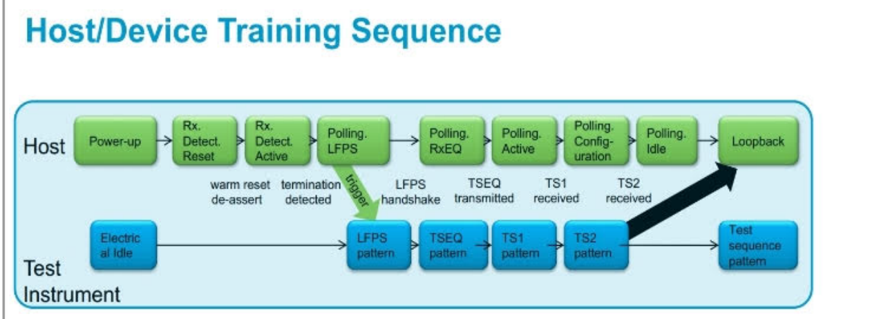
Figure 42. USB3 Loopback entry. For Receiver Jitter Tolerance Test procedures, see Electrical Compliance Test Specification for SuperSpeed USB Rev.
1.0a, section TD.1.5 Receiver Jitter Tolerance Test, which gives the detailed test steps.
3.3.2 Checking USB3 Rx Loopback mode
Device Rx query: cat /sys/kernel/debug/usb/xxxx/link_state, replacing xxxx with the tested USB controller node.
Loopback means Device Rx mode. For Host Rx on Linux 4.19 and earlier, read xHCI PORTSC with io: bits [8:5] PLS = 11 (decimal) mean Loopback mode. Check the chip TRM for the base; the offset is 0x430. RK3399 Host0 PORTSC = 0xfe800430, Host1 = 0xfe900430. On Linux 5.10 and later use cat sys/kernel/debug/usb/xhci/xxxx/ports/port02/portsc, replacing xxxx with the actual xHCI node. Link:Test mode means Host Rx mode.
3.4 USB3 compliance problems and solutions
3.4.1 Device cannot enter Tx mode
USB3 Device normally enters Tx mode without a command. If not, measure VBUS first. The Device Tx Compliance specification prohibits the Device from self-supplying VBUS 5 V; doing so prevents automatic Compliance entry. The fixture must supply VBUS: connect its USB power port to the scope or PC with a USB cable.
3.4.2 RK3399 USB3 issues
-
RK3399 Type-A Host cannot enter Tx: insert a USB3 disk before testing as described in the Host Tx precautions; otherwise entry may fail. Alternatively remove
snps,usb3-warm-reset-on-resume-quirkfrom DTS nodesusbdrd_dwc3_0andusbdrd_dwc3_1. -
RK3399 Type-C Host cannot enter Tx: normally the Host Tx procedure works. Check VBus if it fails; permanently powered VBus may prevent entry. Method 1: make VBus software-controlled, with no 5 V by default and 5 V only after attaching a Type-C-to-Type-A cable. Method 2: set the corresponding DTS
dr_modeto"host". -
RK3399 Type-A Host cannot enter Rx Loopback: first insert a USB3 disk and confirm SuperSpeed in the serial log, proving the firmware supports USB3. Remove the disk and begin testing. Without this step, Type-A may fail to enter Loopback.
-
RK3399 Linux 3.10/4.4 USB3 Host Tx procedure.
Note: applies only to RK3399.
- RK3399 Linux 3.10 / early Linux 4.4. For Type-C0 normal/reversed orientation use the following first/second commands; for Type-C1 use the third/fourth:
echo test_u3 > /sys/kernel/debug/usb@fe800000/host_testmode
echo test_flip_u3 > /sys/kernel/debug/usb@fe800000/host_testmode
echo test_u3 > /sys/kernel/debug/usb@fe900000/host_testmode
echo test_flip_u3 > /sys/kernel/debug/usb@fe900000/host_testmode
- RK3399 newer Linux 4.4: Type-C0 normal/reversed uses commands 1/2, Type-C1 commands 3/4. The final query checks entry. U2: test_packet means U2 test mode; U3: compliance mode means U3 test mode; U3: UNKNOWN means not in test mode.
echo test_u3 > /sys/devices/platform/usb0/host_testmode
echo test_flip_u3 > /sys/devices/platform/usb0/host_testmode
echo test_u3 > /sys/devices/platform/usb1/host_testmode
echo test_flip_u3 > /sys/devices/platform/usb1/host_testmode
cat /sys/kernel/debug/usb3 控制器节点/host_testmode
U2: test_packet // means that U2 in test mode
U3: compliance mode // means that U3 in test mode
3.4.3 RK1808 USB3 issues
- RK1808 Type-A USB3 Host cannot enter Rx Loopback: disable hub autosuspend in software using the following change.
diff --git a/drivers/usb/core/usb.c b/drivers/usb/core/usb.c
index 36e5098..0b2930d 100644
--- a/drivers/usb/core/usb.c
+++ b/drivers/usb/core/usb.c
@@ -66,7 +66,7 @@ int usb_disabled(void)
 EXPORT_SYMBOL_GPL(usb_disabled);

 #ifdef CONFIG_PM
-static int usb_autosuspend_delay = 2;          /* Default delay value,
+static int usb_autosuspend_delay = -1;         /* Default delay value,
3.4.4 RK3588 USB3 issues
RK3588 USB3 Tx/Rx tests on Linux 5.10 require the following precautions.
- Before Type-C0 Device testing, disable controller autosuspend:
echo on > /sys/devices/platform/usbdrd3_0/fc000000.usb/power/control
-
For Type-C Host testing, connect the Type-C fixture to the port first, wait 2–3 seconds for automatic Host switching, then issue the Host command in Table 7.
-
If Rx cannot enter Loopback automatically, add
snps,dis_u3_susphy_quirk;to the DTS DWC3 controller configuration. -
Type-C0 Device Tx:
cat /sys/kernel/debug/usb/fc000000.usb/link_state;Complianceconfirms test mode. -
Type-C0 Device Rx:
cat /sys/kernel/debug/usb/fc000000.usb/link_state;Loopbackconfirms test mode. -
Host Tx, using Type-C1 as the example:
cat sys/kernel/debug/usb/xhci/xhci-hcd.8.auto/ports/port02/portsc;Link:Compliance modeconfirms Host Tx mode. -
Host Rx, using Type-C1 as the example:
cat sys/kernel/debug/usb/xhci/xhci-hcd.8.auto/ports/port02/portsc;Link:Test modeconfirms Host Rx mode.
4. USB3 HUB Compliance Test
Script annotations: the USB2 example has four HUBs, selects HUB[2] then port 2, and quits with q. The USB3 example selects 0 for the SuperSpeed HUB, then 1 for port1 (2 for port2, and so on); q ends testing. Original terminal output and Chinese annotations remain unchanged.
USB3 HUB compliance covers upstream and downstream ports, but practical applications usually test only user-accessible downstream ports, which are the subject here. Common chips include GL352x, VL812, VL813, USB5734, RTS5411 and CYPRESS HX3. Unlike USB2 HUB tests, Rockchip USB3 HUB compliance uses scripts only.
-
Download and compile the test script. Source: https://redmine.rockchip.com.cn/documents/113 , file USB_HUB_Compliance_Test_Script.
-
Run the script: the example tests GL3523 on RK3399. (1) Push the script to Android with adb. (2) Change linux-eye permissions. (3) Run it to enter USB3 HUB port test mode. (3.1) Identify the tested HUB from the kernel log.
adb push C:\Users\user\Desktop\linux-eye /data
root@rk3399:/data # chmod 777 linux-eye
[  139.427845] usb 6-1: new SuperSpeed USB device number 2 using xhci-hcd
[  139.445641] usb 6-1: New USB device found, idVendor=05e3, idProduct=0612
[  139.445708] usb 6-1: New USB device strings: Mfr=1, Product=2, SerialNumber=0
[  139.445738] usb 6-1: Product: USB3.0 Hub
[  139.445763] usb 6-1: Manufacturer: GenesysLogic
[  139.452409] usb 5-1: new high-speed USB device number 2 using xhci-hcd
[  139.463572] hub 6-1:1.0: USB hub found
[  139.465861] hub 6-1:1.0: 4 ports detected
[  139.589854] usb 5-1: New USB device found, idVendor=05e3, idProduct=0610
[  139.589920] usb 5-1: New USB device strings: Mfr=1, Product=2, SerialNumber=0
[  139.589950] usb 5-1: Product: USB2.0 Hub
[  139.589975] usb 5-1: Manufacturer: GenesysLogic
[  139.607244] hub 5-1:1.0: USB hub found
[  139.609146] hub 5-1:1.0: 4 ports detected
(3.2) Execute the test script.
root@rk3399:/ # ./data/linux-eye

LinuxEye - select one of the following hub for testing.

        [ 0]    4-port Super-Speed hub at tier 2 of Bus 6
                (VID: 05E3, PID: 0612, Address: 2)

        [ 1]    4-port High-Speed hub at tier 2 of Bus 5
                (VID: 05E3, PID: 0610, Address: 2)

    Please enter [0 ~ 1] to select a hub or 'q' to quit: 0 (输⼊0,表⽰测试super-speed)
                [ 1] is open
                [ 2] is open
                [ 3] is open
                [ 4] is open
    Please enter [1 ~ 4] to select a port or 'q' to quit: 1 (输⼊1,表⽰测试USB3 HUB
port1,如果测试port2,则输⼊2,以此类推)
    device file /dev/bus/usb/006/002 opened successfully
           Port (1) Status: 02A0
    LinuxEye - Start testing port 1 of device 2 on bus 6    (开始测试)
                Type 'q' to stop the test: q                (测试结束,输⼊q,退出)
(3.3) Repeat for the other USB3 HUB downstream ports.
5. Rockchip USB SQ Tool
Rockchip USB SQ Tool is Rockchip’s USB PHY signal-integrity debugger. It queries test commands, adjusts PHY signals dynamically and generates PHY driver code from the tuning results. See Rockchip_Introduction_USB_SQ_Tool_CN. Download: https://redmine.rockchip.com.cn/documents/113 .
6. References
-
USB 2.0 Specification
-
USB 3.1 Specification
-
Agilent N5416A USB 2.0 Compliance Test Option
-
Agilent USB2.0 High Speed Device SQ Test
-
Keysight N7015A-16A Type-C Test Kit
-
USB 2.0 Electrical Compliance Test Specification Version 1.07
-
Electrical Compliance Test Specification for SuperSpeed USB Rev. 1.0a