
ArmSoM platform reference based on the English and Chinese Rockchip U-Boot Nextdev V2.37.0 developer guides (329 and 314 PDF pages). The source platform-support table is retained below; it is not a blanket support statement for all ArmSoM boards. Match the actual SoC, board DTS, SDK/BSP, U-Boot branch, DDR and trust firmware and kernel before adapting these examples. No ArmSoM hardware validation or performance measurement was performed. Source tests and logs remain source examples. English figures are used in this English edition and in the Russian/German translations.
Source reconciliation: both PDFs carry V2.37.0 and the same 393 numbered headings. This edition retains the complete English technical text and examples in their source order; Chinese is the basis for the Russian/German prose. Page-break fragments differ, not necessarily functionality. Two falsely detected English tables in §§1.11 and 5.3.4 are code, restored as code against both sources. Firmware names in §14.1 (RK3566/RK3568 rows naming rk3588 files) and §14.4 (RK3588 naming rk3568-dfu.config) are preserved source uncertainties, not recommendations to flash another chip’s firmware. Original TODO markers remain unfinished source content. Verify against the actual SDK/TRM. Flash erasure, OTP/eFuse writes, key burning, partition changes and signing/boot examples can irreversibly affect hardware or data; none were executed during preparation.
Further shared source uncertainties: CONFIG_ENV_IS_NOWHERE_XXX in §4.8.2 is retained as written. In the regulator initialization description the source repeats regulator-min-microvolt twice; no silent substitution with another property is made. Some source code examples contain full-width punctuation or typographic quotation marks. Check the actual SDK definitions and syntax before applying any example.
ArmSoM documentation · Rockchip U-Boot source
| Chipset | Miniloader + RKIMG u-boot | SPL + FIT u-boot |
|---|---|---|
| RV1108 | Y | |
| RK3036 | Y | |
| RK3126C | Y | |
| RK3128 | Y | |
| RK3229 | Y | |
| RK3288 | Y | |
| RK3308 | Y | |
| RK3326/PX30 | Y | |
| RK3328 | Y | |
| RK3368/PX5 | Y | |
| RK3399 | Y | |
| RK1808 | Y | |
| RV1126/RV1109 | Y | |
| RK3566/RK3568 | Y | |
| RK3588 | Y | |
| RV1106/RV1103 | Y | |
| RK3528 | Y | |
| RK3562 | Y | |
| RK3576 | Y | |
| RV1106B/RV1103B | Y | |
| RK3506 | Y | |
| RV1126B | Y |
1. Chapter-1 Basic Introduction
1.1 Feature
v2017(next-dev) is the version developed by RK from the official v2017.09 version of U-Boot, and it supports all the mainstream chips sold by RK. The main features supported are: Supports RK Android firmware booting; Supports Android AOSP firmware booting; Supports Linux Distro firmware booting; Supports both Rockchip miniloader and SPL/TPL pre-loader boot; Supports LVDS, EDP, MIPI, HDMI, CVBS, RGB and other display devices. Support eMMC, Nand Flash, SPI Nand flash, SPI NOR flash, SD card, USB flash disk and other storage devices; Supports FAT, EXT2, and EXT4 file systems; Supports GPT, RK parameter partition tables; Supports power-on LOGO, charging animation, low power management, power management; Supports I2C, PMIC, CHARGE, FUEL GUAGE, USB, GPIO, PWM, GMAC, eMMC, NAND, Interrupt, etc; Supports vendor storage saving user data and configuration. Supports RockUSB and Google Fastboot USB gadget to write eMMC; Supports mass storage, ethernet, HID and other USB devices; Supports dynamic selection of kernel DTB by hardware state;
1.2 Version
There are two versions of RK’s U-Boot including v2014 and v2017, internally named rkdevelop and next-dev, respectively. Two methods are available for the user to confirm whether the current U-Boot is the v2017. Method 1: Check whether or not the Makefile version number is 2017.
#
## Chapter-1 SPDX-License-Identifier:      GPL-2.0+
#

VERSION = 2017
PATCHLEVEL = 09
SUBLEVEL =
EXTRAVERSION =
NAME =
......
Method 2: Check whether or not the first official line of the boot print is U-Boot 2017.09.
U-Boot 2017.09-01818-g11818ff-dirty (Nov 14 2019 - 11:11:47 +0800)
......
Project open source: v2017 has been open source and regularly updated to Github: https://github.com/r ockchip-linux/u-boot kernel version: v2017 requires RK kernel version >= 4.4
1.3 DM
DM (Driver Model) is U-Boot’s standard device-driver development model, which is very similar to the kernel’s device-driver model. v2017 also follows the DM framework to develop various functional modules. Hence, it is recommended that readers read the DM documentation first to understand the principles and implementation of the DM architecture. README:
./doc/driver-model/README.txt
Terminology
-----------

Uclass - a group of devices which operate in the same way. A uclass provides
         a way of accessing individual devices within the group, but always
         using the same interface. For example a GPIO uclass provides
         operations for get/set value. An I2C uclass may have 10 I2C ports,
         4 with one driver, and 6 with another.

Driver - some code which talks to a peripheral and presents a higher-level
         interface to it.

Device - an instance of a driver, tied to a particular port or peripheral.
Brief summary: uclass : Device driver model driver device Core code:
./drivers/core/
1.4 Security
U-Boot belongs to Non-Secure World in ARM TrustZone security system, it can’t directly access any secure resources (e.g. secure memory, secure otp, efuse), and needs to use trust to access them indirectly. U-Boot operates in the following mode on RK platforms.
32-bit platform: Non-Secure PL1
64-bit platform:  EL2(Always be Non-Secure)
1.5 Boot-order
The RK platform currently has two sets of startup methods, depending on whether the front-level Loader code is open source or not:
//  Front loader closed source
BOOTROM => ddr bin => Miniloader => TRUST => U-BOOT => KERNEL
// Front loader open source
BOOTROM => TPL => SPL => TRUST => U-BOOT => KERNEL
TPL is equivalent to ddr bin, SPL is equivalent to miniloader. the combination of TPL+SPL realizes the same function as RK closed source ddr.bin+miniloader, and can be replaced by each other.
1.6 Driver-probe
Although U-Boot introduces the device-driver development model, it will not automatically initiate the probe of the registered device-driver as kernel does during the initialization phase. The probe of the driver must be initiated with the user’s active call. The interface is as follows:
int uclass_get_device(enum uclass_id id, int index, struct udevice **devp);
int uclass_get_device_by_name(enum uclass_id id, const char *name,
                              struct udevice **devp);
int uclass_get_device_by_seq(enum uclass_id id, int seq, struct udevice **devp);
int uclass_get_device_by_of_offset(enum uclass_id id, int node, struct udevice **devp);
int uclass_get_device_by_ofnode(enum uclass_id id, ofnode node, struct udevice **devp);
int uclass_get_device_by_phandle_id(enum uclass_id id,
                                    int phandle_id, struct udevice **devp);
int uclass_get_device_by_phandle(enum uclass_id id,
                                 struct udevice *parent, struct udevice **devp);
int uclass_get_device_by_driver(enum uclass_id id,
                                const struct driver *drv, struct udevice **devp);
int uclass_get_device_tail(struct udevice *dev, int ret, struct udevice **devp);
......
Core calls to the above interfaces:
int device_probe(struct udevice *dev);  // Users are recommended to understand the internal
implementation!
1.7 Shell
U-Boot’s Shell is called CLI(Command Line Interface), users can customize CMD according to their needs. In addition to through the Shell, CMD can be called as code through run_command() and run_command_list()`.
int run_command(const char *cmd, int flag)
int run_command_list(const char *cmd, int len, int flag)
1.8 Boot-command
U-Boot eventually boots the kernel with the boot command defined by CONFIG_BOOTCOMMAND . The CONFIG_PREBOOT pre-boot command is also executed before the execution of CONFIG_BOOTCMD , which is usually defined as empty.
1.9 TPL/SPL/U-Boot Proper
By using different compilation conditions, U-Boot can, with the same set of code, get three different functional Loaders, TPL/SPL/U-Boot-proper. TPL (Tiny Program Loader) and SPL (Secondary Program Loader) are loaders at an earlier stage than U-Boot: TPL: Running in sram, responsible for completing ddr initialization; SPL: Running in ddr, responsible for completing the lowlevel initialization of the system, and loading the later firmware (trust.img and uboot.img); U-Boot proper: Running in the ddr, we usually call it “U-Boot”, responsible for booting the kernel; Note: The term U-Boot proper is used to distinguish it from SPL. For the sake of convention, all references to U-Boot proper in subsequent chapters will be abbreviated to U-Boot. Booting process:
BOOTROM => TPL(ddr bin) => SPL(miniloader) => TRUST => U-BOOT => KERNEL
For more, please refer to doc/README.TPL and doc/README.SPL
1.10 Build-output
U-Boot will generate some important files in the root directory after successful compilation of U-Boot(TPL/SPL generated files are only available when TPL/SPL compilation is supported):
// U-Boot phase
./u-boot.map            // MAP table file
./u-boot.sym            // SYMBOL table file
./u-boot                // ELF files, kernel-like vmlinux (important!)
./u-boot.dtb            //  u-boot's own dtb file
./u-boot.bin            // Executable binary file that will be packaged as uboot.img for
                       programming

// SPL phase
./spl/u-boot-spl.map    // MAP table file
./spl/u-boot-spl.sym    // SYMBOL table file
./spl/u-boot-spl        // ELF files, kernel-like vmlinux (important!)
./spl/u-boot-spl.dtb    // spl's own dtb file
./spl/u-boot-spl.bin    // Executable binary file that will be packaged into a loader for
                         programming

// TPL phase
./tpl/u-boot-tpl.map    // MAP table file
./tpl/u-boot-tpl.sym    // SYMBOL table file
./tpl/u-boot-tpl        // ELF files, kernel-like vmlinux (important!)
./tpl/u-boot-tpl.dtb    // tpl's own dtb file
./tpl/u-boot-tpl.bin    // Executable binary file that will be packaged into a loader for
                         programming
1.11 Environment-variables
ENV (Environment-Variables) is a global data management and delivery method supported by U-Boot, the principle is to build a HASH mapping table, and manage user data as “key-data” table entries. EVN is usually used to define platform configuration parameters such as firmware load address, network configuration (ipaddr, serverip), bootcmd, bootargs, which can be printed out by the user using the printenv command at the command line.
Users can choose whether to save ENV data to local storage ENV data is restricted to U-Boot only and cannot be passed directly to the kernel or parsed by the kernel. The user layer can access ENV data through the fw_printenv tool provided by U-Boot The storage address and size of ENV data on the RK platform are defined as follows (unit: byte):
if ARCH_ROCKCHIP
config ENV_OFFSET
        hex
        depends on !ENV_IS_IN_UBI
        depends on !ENV_IS_NOWHERE
        default 0x3f8000
        help
          Offset from the start of the device (or partition)

config ENV_SIZE
        hex
        default 0x8000
        help
          Size of the environment storage area
endif
1.12 U-Boot DTS
U-Boot has its own DTS file, and the corresponding DTB file is automatically generated when compiling, and then being added at the end of u-boot.bin. File directory:
arch/arm/dts/
Which DTS file to use for each platform is specified by CONFIG_DEFAULT_DEVICE_TREE in defconfig.
1.13 Relocation
Usually, during the boot phase, U-Boot is loaded into the low DRAM address by the previous bootloader, and after completing the board_f.c process, U-Boot will relocate itself to a reserved address at the end of the memory (called as relocation, the location depends on the memory layout of the U-Boot). After completing the relocation, the board_r.c process continues. This can be recognized by the boot message:
U-Boot 2017.09-gabfd1c5e3d-210202-dirty #cjh (Mar 08 2021 - 16:57:31 +0800)

Model: Rockchip RK3568 Evaluation Board
PreSerial: 2, raw, 0xfe660000
DRAM:  2 GiB
Sysmem: init
// relocate to ddr where first address offset 0x7d304000. If the offset is 0, no relocation
is executed.

Relocation Offset: 7d304000, fdt: 7b9f8ed8
Using default environment
......
2. Chapter-2 RK Architecture
This chapter introduces users to some important basics, features, etc. on the RK platform.
2.1 Preface
All references to enable/disable CONFIG_ configuration item throughout the text refer to enable or disable it by means of make menuconfig . Except for some special CONFIG_ configuration items that are defined directly in the .h file. Do not enable/disable the CONFIG_ configuration item directly in defconfig to avoid .config not taking effect due to configuration dependencies defined in Kconfig. Please use make savedefconfig when updating defconfig.
2.2 Platform Documentation
Platform catalog:
./arch/arm/include/asm/arch-rockchip/
./arch/arm/mach-rockchip/
./board/rockchip/
./include/configs/
defconfig catalog:
./configs/
Core public board-level documentation!
./arch/arm/mach-rockchip/board.c
2.3 Platform Configuration
configuration file Configuration items, parameters for each platforms are typically located in the following locations:
//Public documents for each platform (developers usually don't need to modify them)
./arch/arm/mach-rockchip/Kconfig
./include/configs/rockchip-common.h

// Unique to each platform, here taking RK3399 as an example
./include/configs/rk3399_common.h
./include/configs/evb_rk3399.h
./configs/rk3399_defconfig
Configuration note: The following describes the important configurations defined in rockchip-common.h, rkxxx_common.h and evb_rkxxx.h. RKIMG_DET_BOOTDEV: Storage type detection command, detects the current storage device type in a scan-by-scan fashion; RKIMG_BOOTCOMMAND: Kernel boot command; ENV_MEM_LAYOUT_SETTINGS: Firmware loading addresses, including ramdisk/fdt/kernel; PARTS_DEFAULT: Default GPT partition table, used in some cases when no valid GPT partition table is found in the store ROCKCHIP_DEVICE_SETTINGS: Peripheral-related commands, mainly specifying stdio (which typically includes display module boost commands); BOOTENV: Booting device detection commands when booting linux in distro mode CONFIG_SYS_MALLOC_LEN: The size of malloc memory pool; CONFIG_SYS_TEXT_BASE: Starting address for U-Boot operation; CONFIG_BOOTCOMMAND: Boot command, typically defined as RKIMG_BOOTCOMMAND; CONFIG_PREBOOT: Pre-boot command, executed before CONFIG_BOOTCOMMAND; CONFIG_SYS_MMC_ENV_DEV: when MMC is used as ENV storage medium, dev num is usually 0 The following is an example of the RK3399: ./include/configs/rockchip-common.h:
......
#define RKIMG_DET_BOOTDEV \                           // Dynamically detects the current
storage type
    "rkimg_bootdev=" \
    "if mmc dev 1 && rkimgtest mmc 1; then " \
        "setenv devtype mmc; setenv devnum 1; echo Boot from SDcard;" \
    "elif mmc dev 0; then " \
        "setenv devtype mmc; setenv devnum 0;" \
    "elif rknand dev 0; then " \
        "setenv devtype rknand; setenv devnum 0;" \
        "elif rksfc dev 0; then " \
                "setenv devtype rksfc; setenv devnum 0;" \
    "fi; \0"

#define RKIMG_BOOTCOMMAND \
    "boot_android ${devtype} ${devnum};" \           // Booting android format firmware
    "bootrkp;" \                                     // Booting RK format firmware
    "run distro_bootcmd;"                            // Booting the linux firmware
......
./include/configs/rk3399_common.h:
......
#ifndef CONFIG_SPL_BUILD
#define ENV_MEM_LAYOUT_SETTINGS \        // Firmware loading address
    "scriptaddr=0x00500000\0" \
    "pxefile_addr_r=0x00600000\0" \
    "fdt_addr_r=0x01f00000\0" \
    "kernel_addr_r=0x02080000\0" \
    "ramdisk_addr_r=0x0a200000\0"

#include <config_distro_bootcmd.h>
#define CONFIG_EXTRA_ENV_SETTINGS \
    ENV_MEM_LAYOUT_SETTINGS \
    "partitions=" PARTS_DEFAULT \        // Default GPT partition table
    ROCKCHIP_DEVICE_SETTINGS \
    RKIMG_DET_BOOTDEV \
    BOOTENV                              // Booting device detection command when booting
                                          linux
#endif

#define CONFIG_PREBOOT                   // Pre-boot commands that are executed before
                                        CONFIG_BOOTCOMMAND
......
./include/configs/evb_rk3399.h:
......
#ifndef CONFIG_SPL_BUILD
#undef CONFIG_BOOTCOMMAND
#define CONFIG_BOOTCOMMAND RKIMG_BOOTCOMMAND // Define boot command (set to
                                              RKIMG_BOOTCOMMAND)
#endif
......
#define ROCKCHIP_DEVICE_SETTINGS \           // Enable display module
        "stdout=serial,vidconsole\0" \
        "stderr=serial,vidconsole\0"
......
2.4 Boot Process
The U-Boot boot process for the RK platform is as follows, only some of the important steps are listed
start.s
    // assembly environment
    => IRQ/FIQ/lowlevel/vbar/errata/cp15/gic   // ARM architecture related lowlevel
                                                initialization
    => _main
        => stack                               // Prepare the stack needed for the C
                                              environment
        // [Phase 1] Initialization of the C environment, initiating a series of function
calls
        => board_init_f: init_sequence_f[]
            initf_malloc
            arch_cpu_init                      // [Lowlevel initialization of SoCs]
            serial_init                        // Serial port initialization
            dram_init                          // [Getting ddr capacity information]
            reserve_mmu                        // Reserve memory from the end of ddr to a
                                                lower address.
            reserve_video
            reserve_uboot
            reserve_malloc
            reserve_global_data
            reserve_fdt
            reserve_stacks
            dram_init_banksize
            sysmem_init
            setup_reloc                        //Determine the address of the U-Boot
                                             itself to be relocated
        // Compilation environment
        => relocate_code                       // Compilation of U-Boot code to implement
relocation
        // [Phase 2] C environment initialization, initiating a series of function calls
        => board_init_r: init_sequence_r[]
            initr_caches                       // Enable MMU and I/Dcache
            initr_malloc
            bidram_initr
            sysmem_initr
            initr_of_live                      // Initialize of_live
            initr_dm                           // Initializing the dm framework
            board_init                         // [Platform initialization, the core part]
                board_debug_uart_init          // Serial port iomux, clk configuration
                init_kernel_dtb                // [Switch to kernel dtb]!
                clks_probe                     // Initialize system frequency
                regulators_enable_boot_on      // Initialize system power
                io_domain_init                 // io-domain initialization
                set_armclk_rate                // __weak, ARM boost (implemented on demand
by the platform)
                dvfs_init                      // wide-temperature chip frequency modulation
and voltage control
                rk_board_init                  // __weak, implemented by each specific
platform
            console_init_r
            board_late_init                    // [Platform late initialization]
                rockchip_set_ethaddr           // Setting the mac address
                rockchip_set_serialno          // Setting serialno
                setup_boot_mode                // Parsing the “reboot xxx” command
                                               // Recognizes key and loader modes, recovery
                charge_display                 // U-Boot charge
                rockchip_show_logo             // Display boot logo
                soc_clk_dump                   // print clk tree
                rk_board_late_init             // __weak, implemented by each specific
platform
            run_main_loop                      // [Enter command line mode, or execute the
boot command]
2.5 Memory Layout
The U-Boot is loaded by the predecessor loader to the CONFIG_SYS_TEXT_BASE address, and initializes by probing the total memory capacity of the current system, which is assumed to be a maximum of 4GB available on 32-bit platforms (but doesn’t affect the kernel’s recognition of the capacity), and all of the memory is assumed to be available on 64-bit platforms. Then, through a series of reserve_xxx() interfaces, it reserves the memory it needs from the end of the memory forward, and finally relocates itself to a certain reserved space. The overall memory usage layout is as follows, using ARM64 as an example (the regular case):
| Name | Start Addr Offset |
Size | Usage | Secure |
|---|---|---|---|---|
| ATF | 0x00000000 | 1M | ARM Trusted Firmware | Yes |
| SHM | 0x00100000 | 1M | SHM, Pstore | No |
| OP-TEE | 0x08400000 | 2M~30M | Refer to the TEE Development Manual |
Yes |
| FDT | fdt_addr_r | - | kernel dtb | No |
| KERNEL | kernel_addr_r | - | kernel image | No |
| RAMDISK | ramdisk_addr_r | - | ramdisk image | No |
| …… | - | - | - | - |
| FASTBOOT | - | - | Fastboot buffer | No |
| …… | - | - | - | |
| SP | - | - | stack | No |
| FDT | - | sizeof(dtb) | U-Boot dtb | No |
| GD | - | sizeof(gd) | - | No |
| Board | - | sizeof(bd_t) | - | No |
| MALLOC | - | CONFIG_SYS_MALLOC_LEN | System heap space | No |
| U-Boot | - | sizeof(mon) | u-boot image | No |
| Video FB | - | fb size | 32M | No |
| TLB Table | RAM_TOP-64K | 32K | MMU Page Table | No |
The Start Addr Offset column in the above table indicates the address offset based on the DDR base; Fastboot address and size are determined by configuration: CONFIG_FASTBOOT_BUF_ADDR, CONFIG_FASTBOOT_BUF_SIZE. Video FB/U-Boot/Malloc/Board/Gd/Fdt/Sp is allocated from top to bottom based on actual requirement size;; 64-bit platforms: ATF is required for ARMv8, OP-TEE is optional; 32-bit platforms: only OP-TEE available kernel fdt/kernel/ramdisk is the address of the firmware that U-Boot needs to load, defined by ENV_MEM_LAYOUT_SETTINGS ; The address and size of the buffer needed for Fastboot functionality is defined in defconfig; The space occupied by OP-TEE needs to be based on the actual demand, the maximum is 30M; where OP-TEE on RK1808/RK3308 is placed at the low address, not at 0x8400000;
2.6 Storage Layout
The storage layout of the RK linux program is as follows, and the Android program is basically the same except that the definition of boot/rootfs is different from that of the linux platform, which can be used for reference.
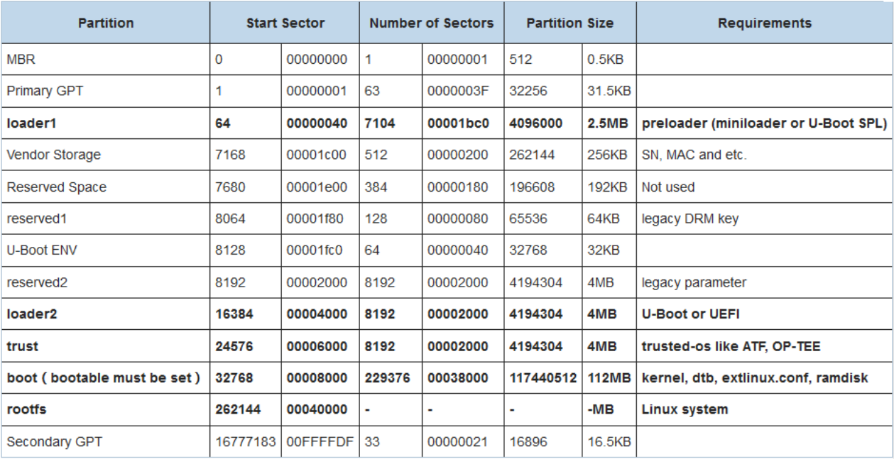
Picture reference: http://opensource.rock-chips.com/wiki_Partitions
2.7 Aliases
There are some special aliases in U-Boot that differ from those defined in the kernel DTS. eMMC/SD are collectively referred to as mmc devices in U-Boot, using numbers 0 and 1 for differentiation; SD has a higher boot priority than eMMC.
mmc1: indicates sd
mmc0: indicates emmc
2.8 AMP
U-Boot for RK platform supports AMP (Asymmetric Multi-Processing) firmware boot. For more references please check Driver Modules section.
2.9 Atags
The booting process of the RK platform:
BOOTROM => ddr-bin => Miniloader => TRUST => U-BOOT => KERNEL
Some configuration information can be passed between the various levels of firmware on the RK platform via the ATAGS mechanism. Scope of application: ddr-bin, miniloader, trust, U-Boot, excluding Kernel Passed content: serial port configuration, storage type, memory occupied by ATF and OP-TEE, ddr capacity, etc. Code implementation:
./arch/arm/include/asm/arch-rockchip/rk_atags.h
./arch/arm/mach-rockchip/rk_atags.c
2.10 Bidram/Sysmem
U-Boot can use all the memory of the system, and reserve the memory needed by the system from the high address to the low address, after reserving the memory, there is usually still a large memory space left. U- Boot does not have a mechanism to manage this space, so the RK platform introduces the mechanism of bidram, sysmem memory block to manage this block of memory. Thus, together with U-Boot’s existing malloc management mechanism, the RK platform manages all system memory through sysmem + bidram + malloc, preventing problems such as memory conflicts.
low-addr                                                                    high-addr
|-----------------------------------------------------------|-----------------|
|             no management                                 | system used     |
|-----------------------------------------------------------|-----------------|
0x0                                                                          N GB
bidram: Manage memory blocks that are unavailable at u-boot and kernel stage and need to be eliminated, e.g. space occupied by ATF and OP-TEE.
sysmem: Manages blocks of memory visible and available to the kernel. For example, the space occupied by fdt, ramdisk, kernel, and fastboot. Related Code:
./lib/sysmem.c
./lib/bidram.c
./include/memblk.h
./arch/arm/mach-rockchip/memblk.c
The following table shows the memory management information for bidram and sysmem, which is dumped when a block is initialized or allocated abnormally. The following is a brief description. bidram memory information table:
bidram_dump_all:
    --------------------------------------------------------------------
    // <1> Here shows the total capacity information of the ddr that U-Boot got from the
previous loader, which is 2GB in total
    memory.rgn[0].addr     = 0x00000000 - 0x80000000 (size: 0x80000000)

    memory.total           = 0x80000000 (2048 MiB. 0 KiB)
    --------------------------------------------------------------------
    // <2> This shows information about the memory that has been set aside for each
firmware, which is unvisible to the kernel.
    reserved.rgn[0].name   = "ATF"
                   .addr   = 0x00000000 - 0x00100000 (size: 0x00100000)
    reserved.rgn[1].name   = "SHM"
                   .addr   = 0x00100000 - 0x00200000 (size: 0x00100000)
    reserved.rgn[2].name   = "OP-TEE"
                   .addr   = 0x08400000 - 0x0a200000 (size: 0x01e00000)

    reserved.total         = 0x02000000 (32 MiB. 0 KiB)
    --------------------------------------------------------------------
    // <3> Here is how the core algorithm organizes the reserved information for <2> above,
e.g., it will merge adjacent blocks
    LMB.reserved[0].addr   = 0x00000000 - 0x00200000 (size: 0x00200000)
    LMB.reserved[1].addr   = 0x08400000 - 0x0a200000 (size: 0x01e00000)

    reserved.core.total    = 0x02000000 (32 MiB. 0 KiB)
    --------------------------------------------------------------------
sysmem memory information table:
sysmem_dump_all:
    --------------------------------------------------------------------
    // <1> Here is the total amount of memory that sysmem can manage, i.e., the amount of
available ddr, excluding bidram <3>, visible to the kernel.
    memory.rgn[0].addr     = 0x00200000 - 0x08400000 (size: 0x08200000)
    memory.rgn[1].addr     = 0x0a200000 - 0x80000000 (size: 0x75e00000)

    memory.total           = 0x7e000000 (2016 MiB. 0 KiB)
    --------------------------------------------------------------------
    // <2> This shows information about the memory blocks allocated away by each firmware
    allocated.rgn[0].name  = "U-Boot"
                    .addr  = 0x71dd6140 - 0x80000000 (size: 0x0e229ec0)
    allocated.rgn[1].name  = "STACK"      <Overflow!> // Indicates stack overflow
                    .addr  = 0x71bd6140 - 0x71dd6140 (size: 0x00200000)
    allocated.rgn[2].name  = "FDT"
                    .addr  = 0x08300000 - 0x08316204 (size: 0x00016204)
    allocated.rgn[3].name  = "KERNEL"     <Overflow!> // Indicates a memory block overflow
                    .addr  = 0x00280000 - 0x014ce204 (size: 0x0124e204)
    allocated.rgn[4].name  = "RAMDISK"
                    .addr  = 0x0a200000 - 0x0a3e6804 (size: 0x001e6804)
    // <3>  size of malloc_r/f
    malloc_r: 192 MiB, malloc_f: 16 KiB

    allocated.total        = 0x0f874acc (248 MiB. 466 KiB)
    --------------------------------------------------------------------
    // <4> Here's the information that the core algorithm organizes for the above <2>,
showing information about occupied memory blocks
    LMB.reserved[0].addr   = 0x00280000 - 0x014ce204 (size: 0x0124e204)
    LMB.reserved[1].addr   = 0x08300000 - 0x08316204 (size: 0x00016204)
    LMB.reserved[2].addr   = 0x0a200000 - 0x0a3e6804 (size: 0x001e6804)
    LMB.reserved[3].addr   = 0x71bd6140 - 0x80000000 (size: 0x0e429ec0)

    reserved.core.total    = 0x0f874acc (248 MiB. 466 KiB)
    --------------------------------------------------------------------
The following are some common error printouts. When these exceptions occur, analyze them in conjunction with the bidram and sysmem dump memory information above.
//The memory expected to be requested is already occupied by other firmware and there is
memory overlap. This indicates that the current system's memory block usage is not planned
properly
Sysmem Error: "KERNEL" (0x00200000 - 0x02200000) alloc is overlap with existence "RAMDISK"
(0x00100000 - 0x01200000)

// Memory expected to be requested could not be requested for some specific reason (analyze
sysmem and bidram messages)
Sysmem Error: Failed to alloc "KERNEL" expect at 0x00200000 - 0x02200000 but at 0x00400000 -
0x0420000

// sysmem manages space starting at 0x200000, so it simply can't claim space starting at
0x100000
Sysmem Error: Failed to alloc "KERNEL" at 0x00100000 - 0x02200000

// Duplicate request for “RAMDISK” memory block.
Sysmem Error: Failed to double alloc for existence "RAMDISK"
2.11 Fuse/OTP
The RK platform enables secure-boot mode (without the need of downloading efuse/otp ) by signing the firmware for easy debugging of secure-boot. Miniloader will append a cmdline to the kernel via U-Boot to indicate whether the current efuse/otp enabling has been downloaded or not: “fuse.programmed=1” : Secure-boot is enabled, efuse/otp is already downloaded. “fuse.programmed=0” : Secure-boot is enbaled and efuse/otp has not been downloaded. No fuse.programmed in cmdline: secure-boot is not enabled (Miniloader doesn’t pass), or Miniloader is too old to support passing. U-Boot needs to include the following commits:
83c9bd4 board: rockchip: pass fuse programmed state to kernel
2.12 Hotkey
RK platform provides serial port key combination to trigger some events for debugging and downloading (if you can’t trigger it, please try again; invalid when secure-boot is enabled). when booting, long pressing : ctrl+c: Enter U-Boot command line mode; ctrl+d: Enter loader mode; ctrl+b: Enter maskrom mode ctrl+f: Enter fastboot mode; ctrl+m: Print bidram/system information ctrl+i: Enabling kernel initcall_debug ctrl+p: Print cmdline information ctrl+s: “Starting kernel…” After that, enter U-Boot command line;
2.13 Image Decompress
64-bit machines usually download Image, which is loaded by U-Boot to the target running address. U- Boot for RK platforms can also support decompression of 64-bit LZ4 compressed kernels. However, to achieve that, the user must enable:
CONFIG_LZ4=y
The pre and post decompression addresses of the 64-bit LZ4 compression kernel must be defined in the rkxxx_common.h file for each platform:
#define ENV_MEM_LAYOUT_SETTINGS \
    "scriptaddr=0x00500000\0" \
    "pxefile_addr_r=0x00600000\0" \
    "fdt_addr_r=0x01f00000\0" \
    "kernel_addr_no_bl32_r=0x00280000\0" \
    "kernel_addr_r=0x00680000\0" \        // Address of the LZ4 decompression kernel
    "kernel_addr_c=0x02480000\0" \        // Address of the LZ4 compression kernel
    "ramdisk_addr_r=0x04000000\0"
32-bit machines usually download zImage, which is loaded by U-Boot to the kernel_addr_r address, and then self-decompressed by the kernel. U-Boot for RK platforms can also support Image format, which is loaded by U-Boot to the target runtime address. Currently the rkxxx_common.h file for each platform only defines the kernel_addr_r but not the kernel_addr_c address.
Users don’t need to change the configuration, cause U-Boot will determine whether it is currently zImage or Image, and process these 2 addresses dynamically. But user must disable:
CONFIG_SKIP_RELOCATE_UBOOT
32-bit kernel loading address definition.
#define ENV_MEM_LAYOUT_SETTINGS \
    "scriptaddr=0x60000000\0" \
    "pxefile_addr_r=0x60100000\0" \
    "fdt_addr_r=0x68300000\0" \
    "kernel_addr_r=0x62008000\0" \       // zImage compressed kernel address
    "ramdisk_addr_r=0x6a200000\0"
2.14 Image Kernel
U-Boot for the RK platform supports three formats of kernel firmware boot: RK format The magic of the image file is “KRNL”:
00000000   4B 52 4E 4C  42 97 0F 00  1F 8B 08 00  00 00 00 00  KRNL..y.........
00000010   00 03 A4 BC  0B 78 53 55  D6 37 BE 4F  4E D2 A4 69  .....xSU.7.ON..i
kernel.img = kernel; resource.img = dtb + logo.bmp + logo_kernel.bmp; boot.img = ramdisk; recovery.img = ramdisk(for recovery) ; Android format The magic of the image file is “ANDROID!”:
00000000   41 4E 44 52  4F 49 44 21  24 10 74 00  00 80 40 60  ANDROID!$.t...@`
00000010   F9 31 CD 00  00 00 00 62  00 00 00 00  00 00 F0 60  .1.....b.......`
boot.img = kernel + ramdisk+ resource + <dtb>; recovery.img = kernel + ramdisk(for recovery) + resource + <recovery_dtbo> + <dtb>; Notes: recovery_dtbo: images added only since Android-9.0; dtb: images added only since Android-10.0; Distro format One common firmware packaging format for open source Linux is to package ramdisk, dtb, and kernel into an image. This image usually exists in a sertain file system format, such as ext2, ext4, fat, etc. U- Boot needs to access its contents through the file system. For more information, please refer to:
./doc/README.distro
./include/config_distro_defaults.h
./include/config_distro_bootcmd.h
Boot priority: android > rk > distro, each type of firmware has a corresponding boot command, and the three commands will be executed one by one in order of priority until the firmware is booted up. If all commands fail, it stays in U-Boot command line mode. Boot Priority Definition:
#define RKIMG_BOOTCOMMAND \
    "boot_android ${devtype} ${devnum};" \
    "bootrkp;" \
    "run distro_bootcmd;"
2.15 Image U-Boot
There are two firmware formats for U-Boot and trust for RK platforms: the RK and FIT formats are booted by Miniloader and SPL respectively. The current SDK released by Rockchip takes RV1126 as the seperating point, platforms after RV1126 use FIT format, and platforms before RV1126 use RK format. RK format Rockchip’s customized firmware formats, U-Boot and trust are packaged as uboot.img and trust.img respectively. as follows: The uboot.img and 32-bit trust.img images have the magic “LOADER”.
00000000  4c 4f 41 44 45 52 20 20  00 00 00 00 00 00 00 00  |LOADER  ........|
00000010  00 00 20 00 78 d0 0f 00  06 99 c2 a8 20 00 00 00  |.. .x....... ...|
00000020  09 8a b0 e1 89 7a c2 89  0d e8 da ef 86 3e f2 24  |.....z.......>.$|
The 64-bit trust.img image file has the magic “BL3X”.
00000000  42 4c 33 58 00 01 00 00  23 00 00 00 f8 00 04 00  |BL3X....#.......|
00000010  00 00 00 00 00 00 00 00  00 00 00 00 00 00 00 00  |................|
FIT format The U-Boot mainline supports an extremely flexible firmware format, with U-Boot, trust and mcu firmware packaged together as uboot.img. The image file of uboot.img has the magic “d0 0d fe ed”, with the command fdtdump uboot.img you can view the firmware header.
00000000  d0 0d fe ed 00 00 06 00  00 00 00 58 00 00 04 c4  |...........X....|
00000010  00 00 00 28 00 00 00 11  00 00 00 10 00 00 00 00  |...(............|
For more references: please check FIT section. Backup Packaging Usually, uboot.img and trust.img are packaged with multiple backups in order to cope with the possibility of firmware corruption due to power failure during the OTA upgrade process and so on.
| Firmware | Size per copy | Number of copies |
|---|---|---|
| RK uboot.img | 1MB | 4 |
| RK 32-bit trust.img | 1MB | 4 |
| RK 64-bit trust.img | 2MB | 2 |
| FIT uboot.img | 2MB | 2 |
As you can see from the table above, both uboot.img and trust.img are 4MB in size by default. Methods for modifying the size for per copy and number of copies RK format: add parameters to the compiling command. For example: -sz-uboot 2048 1 and - sz-trust 4096 1 , means uboot.img single copy size is 2M, with 1 copy packaged; trust.img single copy size is 4M, with 1 copy packaged. FIT Format: change the configuration parameters: CONFIG_SPL_FIT_IMAGE_KB and CONFIG_SPL_FIT_IMAGE_MULTIPLE, which indicate the single copy size (in KB) and the number of packaged copies, respectively.
Note: SPL determines the location and number of backup items in uboot.img according to CONFIG_SPL_FIT_IMAGE_KB or CONFIG_SPL_FIT_IMAGE_MULTIPLE.If the developer changes these two options, it must append the parameter –spl-new to make.sh so that the generated Loader will contain the u-boo-spl.bin generated by the real-time compilation.Otherwise, the u- boo-spl.bin submitted in rkbin is packed by default (the default is to find the backup items in uboot.img as per 2MB*2).
2.16 Interrupt
U-Boot’s native code does not have full support for interrupts, and the RK platform improves this feature to support GIC-V2 and GIC-V3. Please refer to Driver Modules section for more.
2.17 Kernel-DTB
Native U-Boot only supports the use of U-Boot’s own DTB, RK platform adds support for kernel DTB mechanism, i.e., using kernel DTB to initialize peripherals. The main purpose is to be compatible with peripheral board-level differences, such as: power, clock, display and so on. Role of the two: U-Boot DTB: Responsible for initializing devices such as devices for storaging and printing serial ports; Kernel DTB: Responsible for initializing devices other than devices for storaging and printing serial ports; When U-Boot initializes, it first uses the U-Boot DTB to complete the storage and print serial port initialization, and then loads the Kernel DTB from the storage and turns to this DTB to continue to initialize the rest of the peripherals.The code for the Kerne DTB is implemented in the function: init_kernel_dtb(). Developers generally do not need to modify the U-Boot DTB (unless the print serial port is replaced), the defconfig used in the SDKs released for each platform has the kernel DTB mechanism enabled. So usually for peripheral DTS modification, user should modify kernel DTB. About U-Boot DTB: DTS directory:
./arch/arm/dts/
After enabling the kernel DTB mechanism: the compilation phase will filter out the nodes with u-boot,dm- pre-reloc and u-boot,dm-spl attributes from the U-Boot DTS, and on top of that, it will exclude the property specified by the CONFIG_OF_SPL_REMOVE_PROPS from defconfig, and finally generate the u-boot.dtb file and append it to the end of the u-boot.bin.
Users can check the DTB content by fdtdump command after compiling U-Boot:
fdtdump ./u-boot.dtb | less
For more references: please check Advanced Principles section
2.18 MMU Cache
RK platform enables MMU, Dcache and Icache by default, MMU adopts 1:1 linear mapping, and Dcache adopts write-back policy. Related interfaces:
// Icache interface:
void icache_enable (void);
void icache_disable (void);
void invalidate_icache_all(void);

// Dcache interface:
void dcache_disable (void);
void dcache_enable(void);
void flush_dcache_range(unsigned long start, unsigned long stop);
void flush_cache(unsigned long start, unsigned long size);
void flush_dcache_all(void);
void invalidate_dcache_range(unsigned long start, unsigned long stop);
void invalidate_dcache_all(void);
// Remap the Dcache attributes of a block of memory intervals
void mmu_set_region_dcache_behaviour(phys_addr_t start, size_t size,
                                     enum dcache_option option)
2.19 Make.sh
make.sh is both a compilation script and a packaging and debugging tool, can be used to disassemble and package firmware.
// help command
./make.sh --help

// Functions of packaging firmware
./make.sh trust              // packaging trust
./make.sh loader             // packaging loader
./make.sh trust <ini-file>   // Specify ini file when packaging trust
./make.sh loader <ini-file>  // Specify ini file when packaging loader
./make.sh spl                // Replace ddr and miniloader with tpl+spl, and packaged as
loader
./make.sh spl-s              // Replace miniloader with spl, packaged as loader
./make.sh itb                // Packaging u-boot.itb (64-bit platforms only support
packaging ATF and U-Boot, OP-TEE does not)
./make.sh env                // Generate fw_printenv tool

// Disassembly Functions
./make.sh elf-[x] [type]     // Disassembly: Use the -[x] parameter, [type] to select
whether to disassemble SPL or TPL.
./make.sh elf                // Disassemble the u-boot file, using the -D parameter by
default.
./make.sh elf-S              // Disassemble the u-boot file, using the -S parameter
./make.sh elf-d              // Disassemble the u-boot file, using the -d parameter
./make.sh elf spl            // Disassemble the tpl/u-boot-tpl file, using the -D parameter
by default.
./make.sh elf tpl            // Disassemble the spl/u-boot-tpl file, use the -D parameter by
default
./make.sh <addr>             // Requires the function name and code location corresponding
to addr
./make.sh map                // open u-boot.map
./make.sh sym                // open u-boot.sym
2.20 HW-ID DTB
The U-Boot of the RK platform can filter the DTBs that match the hardware state from multiple DTB files to be loaded based on the hardware state of the GPIOs or ADCs. For more reference: please check the System Modules section.
2.21 Partition Table
U-Boot for RK platform supports two kinds of partition table: RK parameter format (old) and standard GPT format (new), when there are two kinds of partition table on the machine, the GPT partition table is preferred. No matter it is GPT format or RK parameter formatr, when making downloading, the partition table file used is called parameter.txt, users can confirm whether it is GPT or not through the “TYPE: GPT” attribute.
FIRMWARE_VER:8.1
MACHINE_MODEL:RK3399
MACHINE_ID:007
MANUFACTURER: RK3399
MAGIC: 0x5041524B
ATAG: 0x00200800
MACHINE: 3399
CHECK_MASK: 0x80
PWR_HLD: 0,0,A,0,1
TYPE: GPT               // Partition table in GPT format is under using, otherwise it is RK
paramter format
CMDLINE:mtdparts=rk29xxnand:0x00002000@0x00004000(uboot),0x00002000@0x00006000(trust),0
x00002000@0x00008000(misc),0x00008000@0x0000a000(resource),0x00010000@0x00012000(kernel
),0x00010000@0x00022000(boot),0x00020000@0x00032000(recovery),0x00038000@0x00052000(bac
kup),0x00002000@0x0008a000(security),0x00100000@0x0008c000(cache),0x00500000@0x0018c000
(system),0x00008000@0x0068c000(metadata),0x00100000@0x00694000(vendor),0x00100000@0x007
96000(oem),0x00000400@0x00896000(frp),-@0x00896400(userdata:grow)
2.22 Relocation
U-Boot will relocate itself to an address at the end of memory after completing the board_f.c process, depending on the U-Boot memory layout. RK’s U-Boot default: 32-bit platforms: CONFIG_SKIP_RELOCATE_UBOOT=y does not have relocation, otherwise it does.
64-bit platforms have relocation.
2.23 Reset
U-Boot reset, like kernel, eventually needs to be done in trust. U-Boot command line mode can support the same reboot xxx commands as the kernel (depending on the definition in the kernel dts)
2.24 Sd/Udisk
U-Boot for RK platform supports firmware booting or upgrading from SD/U disk. Among them: SD booting/upgrading is supported from the bootrom level onwards USB flash drive booting/upgrading is supported from the U-Boot level onwards For more reference: please check System Modules section.
2.25 Stacktrace
Native U-Boot does not support call stack traceback mechanism, however, RK platform added the function. Currently there are a total of 3 ways to trigger call stack printing: Automatically triggered when the system crashes; User-initiated call to dump_stack(); Enable CONFIG_ROCKCHIP_DEBUGGER ; For example, system abort:
"Synchronous Abort" handler, esr 0x96000010

// abort reason, pc, lr, sp
* Reason:        Exception from a Data abort, from current exception level
* PC         =   000000000028f430
* LR         =   00000000002608d0
* SP         =   00000000f3dceb30

...

// Highlighting PC and LR
Call trace:
  PC:   [< 0028f430 >]
  LR:   [< 002608d0 >]

// Function call relationships
Stack:
        [< 0028f430 >]
        [< 0028da24 >]
        [< 00211600 >]
        [< 002117b0 >]
        [< 00202910 >]
        [< 00202aa8 >]
        [< 0027698c >]
        [< 002151ec >]
        [< 00201b2c >]

// Instructs the user to convert the above call stack information
Copy info from "Call trace..." to a file(eg. dump.txt), and run
command in your U-Boot project: ./scripts/stacktrace.sh dump.txt
According to the above instructions, the user copies the call stack information to any txt file (such as dump.txt) and executes the following command:
cjh@Ubuntu:~/u-boot$ ./scripts/stacktrace.sh dump.txt

// Symbol Table Sources
SYMBOL File: ./u-boot.sym

// Highlight the code locations corresponding to PC and LR
Call trace:
 PC:   [< 0028f430 >]  strncpy+0xc/0x20      ./lib/string.c:98
 LR:   [< 002608d0 >]  on_serialno+0x10/0x1c ./drivers/usb/gadget/g_dnl.c:217

// Converted to get the real function name
Stack:
       [< 0028f430 >]  strncpy+0xc/0x20
       [< 0028da24 >]  hdelete_r+0xcc/0xf0
       [< 00211600 >]  _do_env_set.isra.0+0x70/0x1b8
       [< 002117b0 >]  env_set+0x3c/0x58
       [< 00202910 >]  rockchip_set_serialno+0x54/0x140
       [< 00202aa8 >]  board_late_init+0x5c/0xa0
       [< 0027698c >]  initcall_run_list+0x58/0x94
       [< 002151ec >]  board_init_r+0x20/0x24
       [< 00201b2c >]  relocation_return+0x4/0x0
Notes: There are three types of conversion commands, please follow the instructions after the call stack printout to determine which one to use
./scripts/stacktrace.sh ./dump.txt        // Parsing Call Stack Information from U-
Boot
./scripts/stacktrace.sh ./dump.txt tpl    // Parsing call stack information from tpl
./scripts/stacktrace.sh ./dump.txt spl    // Parsing call stack information from spl
When executing this command, the firmware on the current machine must match the current code environment to be meaningful!Otherwise you will get an incorrect conversion.
2.26 TimeCost
The end of U-Boot initialization prints the total elapsed time for this phase by default:
### Booting Android Image at 0x02007800 ...
Kernel load addr 0x02008000 size 8062 KiB
### Flattened Device Tree blob at 08300000
   Booting using the fdt blob at 0x8300000
   XIP Kernel Image ... OK
  'reserved-memory' dma-unusable@fe000000: addr=fe000000 size=1000000
  'reserved-memory' ramoops@00000000: addr=8000000 size=f0000
   Using Device Tree in place at 08300000, end 08316ed1
Adding bank: 0x00000000 - 0x08400000 (size: 0x08400000)
Adding bank: 0x09200000 - 0x80000000 (size: 0x76e00000)
Total: 812.613 ms    //Total elapsed time for the U-Boot phase

Starting kernel ...
The user can open debug() and DEBUG in lib/initcall.c to get the following process timings, the function addresses can be obtained with the help of . /make.sh for disassembly.
U-Boot 2017.09-00019-g9b55ed0-dirty (Dec 26 2019 - 14:45:33 +0800)

                                         #    5212 us # 137.868 ms
initcall: 0020de1f
                                         #       1 us # 142.636 ms
initcall: 0020e015
Model: Evb-RK3288
                                         #    1646 us # 149. 48 ms
initcall: 0020dd61
PreSerial: 2
                                         #    1213 us # 155. 28 ms
initcall: 0020ddcd
DRAM:                                    #     606 us # 160.401 ms
initcall: 00203719
              // The following 187 us is the time consumed by initcall: 00203719 call
              // The following 165.355 ms is the U-Boot boot time until initcall: 00203719
                                         #     187 us # 165.355 ms
initcall: 0020de81
                                         #       2 us # 169.938 ms
initcall: 0020dc29
                                         #       1 us # 174.703 ms
initcall: 0020dc3d
                                         #       1 us # 179.469 ms
initcall: 0020ddad
                                         #       2 us # 184.237 ms
initcall: 0020de27
                                         #       1 us # 189.  2 ms
......
2.27 TimeStamp
Kernel’s print message has a timestamp by default, which is convenient for users to pay attention to the time.U-Boot’s print message doesn’t have a timestamp by default, users can enable the configuration CONFIG_BOOTSTAGE_PRINTF_TIMESTAMP if necessary.
[    0.324987] U-Boot 2017.09-00019-g9b55ed0-dirty (Dec 26 2019 - 14:31:44 +0800)

[    0.327215] Model: Evb-RK3288
[    0.330039] PreSerial: 2
[    0.332526] DRAM:  2 GiB
[    0.336454] Relocation Offset: 00000000, fdt: 7be22c38
[    0.346981] Using default environment

[    0.351075] dwmmc@ff0c0000: 1, dwmmc@ff0f0000: 0
[    0.394136] Bootdev(atags): mmc 0
[    0.394272] MMC0: High Speed, 52Mhz
[    0.395276] PartType: EFI
[    0.400347] Android 9.0, Build 2019.6
[    0.402070] boot mode: None
[    0.405213] Found DTB in boot part
[    0.407833] DTB: rk-kernel.dtb
[    0.418211] ANDROID: fdt overlay OK
[    0.432128] I2c0 speed: 400000Hz
[    0.435916] PMIC:  RK808
[    0.439113] vdd_arm 1100000 uV
[    0.444148] vdd_gpu 1100000 uV
......

[    1.005018] ## Booting Android Image at 0x02007800 ...
[    1.009917] Kernel load addr 0x02008000 size 8062 KiB
[    1.014981] ## Flattened Device Tree blob at 08300000
[    1.019970]    Booting using the fdt blob at 0x8300000
[    1.025185]    XIP Kernel Image ... OK
[    1.035469]   'reserved-memory' dma-unusable@fe000000: addr=fe000000 size=1000000
[    1.037448]   'reserved-memory' ramoops@00000000: addr=8000000 size=f0000
[    1.044412]    Using Device Tree in place at 08300000, end 08316ed1
[    1.064363] Adding bank: 0x00000000 - 0x08400000 (size: 0x08400000)
[    1.064976] Adding bank: 0x09200000 - 0x80000000 (size: 0x76e00000)
[    1.075259] Total: 812.613 ms

[    1.075279] Starting kernel ...
......:
Notes: The timestamp prints relative time, not absolute time.
2.28 Vendor Storage
The U-Boot of RK platform provides a Vendor storage area for users to save SN, MAC and other information. The storage offset is as follows (see vendor.c for details):
#define EMMC_VENDOR_PART_OFFSET     (1024 * 7)
/* --- Spi Nand/SLC/MLC large capacity case define --- */
#define NAND_VENDOR_PART_OFFSET     0
/* --- Spi/Spi Nand/SLC/MLC small capacity case define --- */
#define FLASH_VENDOR_PART_OFFSET    8
......
Users generally do not need to concern themselves with and modify storage offsets, only with the read and write interfaces:
int vendor_storage_read(u16 id, void *pbuf, u16 size)
int vendor_storage_write(u16 id, void *pbuf, u16 size)
3. Chapter-3 Compile and Download
3.1 Preparations
Download rkbin Rkbin is a toolkit repository for RK’s non-open-source bin, script, and packaging tools. U-Boot compiles from this repository and indexes the relevant files to package the loader, trust, and uboot firmware. Rkbin and the U-Boot project must be kept in the same directory-level. rkbin downloading: please refer to the Appendix. Download GCC The GCC compiler uses gcc-linaro-6.3.1 and is placed in the prebuilts directory. The prebuilts and U- Boot shall maintain a sibling directory relationship.
// 32-bit:
prebuilts/gcc/linux-x86/arm/gcc-linaro-6.3.1-2017.05-x86_64_arm-linux-gnueabihf
// 64-bit:
prebuilts/gcc/linux-x86/aarch64/gcc-linaro-6.3.1-2017.05-x86_64_aarch64-linux-gnu/
GCC downloading: please refer to the Appendix section select defconfig: Please refer to the Platform Definition section. config fragment introduction Due to the differentiated needs of products on a single platform, a defconfig can no longer satisfy. So from RV1126 onwards, we support config fragment, i.e. overlaying the defconfig. For example, if CONFIG_BASE_DEFCONFIG=“rv1126_defconfig” is specified in rv1126-emmc-tb.config, when the . /make.sh rv1126-emmc-tb command is executed, it will first generate the .config with rv1126_defconfig, and then overlay the .config with the configuration in rv1126-emmc-tb.config. This command is equivalent to:
make rv1126_defconfig rv1126-emmc-tb.config && make
To make updates to the config fragment file, simply resort to . /scripts/sync-fragment.sh .
Example:
./scripts/sync-fragment.sh configs/rv1126-emmc-tb.config
Command effect: diff the configuration difference entries of the current .config and rv1126_defconfig into the rv1126-emmc-tb.config file.
3.2 Firmware Compiling
Compiling command:
./make.sh [board] // [board]: configs/[board]_defconfig file.
First- time compilation: Regardless of 32-bit or 64-bit platforms, the first time you specify defconfig or want to re-specify defconfig, the compiling command must specify [board].
Example:
./make.sh rk3399                // build for rk3399_defconfig
./make.sh evb-rk3399            // build for evb-rk3399_defconfig
./make.sh firefly-rk3288        // build for firefly-rk3288_defconfig
Secondary compilation: Regardless of 32-bit or 64-bit platforms, if you want to compile based on the current “.config”, you don’t need to specify [board] in the compiling command.:
./make.sh
Note: If the compilation fails due to strange problems during compilation, try make distclean and recompile. Firmware generation: When the compilation is complete, the following information is generated in the U- Boot root directory: trust, uboot, loader.:
// compile...
....

// uboot packaging process
load addr is 0x60000000!
pack input u-boot.bin
pack file size: 478737
crc = 0x840f163c
uboot version: v2017.12 Dec 11 2017
pack uboot.img success!
pack uboot okay! Input: u-boot.bin

// loader packaging process and the referenced ini file
out:rk3126_loader_v2.09.247.bin
fix opt:rk3126_loader_v2.09.247.bin
merge success(rk3126_loader_v2.09.247.bin)
pack loader okay! Input: /home/cjh/rkbin/RKBOOT/RK3126MINIALL.ini

// trust packaging process and the referenced ini file
 load addr is 0x68400000!
pack file size: 602104
crc = 0x9c178803
trustos version: Trust os
pack ./trust.img success!
trust.img with ta is ready
pack trust okay! Input: /home/cjh/rkbin/RKTRUST/RK3126TOS.ini
// Prompts for a successful compilation. Note: This is prompted even if the above trust and
loader packaging fails, indicating that at least uboot.img was generated
Platform RK3126 is build OK, with new .config(make rk3126_defconfig)
Eventually, downloadable firmware is generated in the root directory:
./uboot.img
./trust.img    // Note: If the firmware is in fit format, there is no trust.img. the trust
binary is packed in uboot.img.
./rk3126_loader_v2.09.247.bin
Firmware packaging tool: Please refer to the Tools section.
3.3 Firmware Downloading
Downloading tool: The firmware downloading tool for Windows/Linux is recommended to use the tool version released by the SDK or the latest version. Downloading mode: The RK platform has a total of two downloading modes: Maskrom mode and Loader mode (U-Boot).
-
How to enter Loader mode: When powering on, long press Volume + button When powering on, the host computer long presses ctrl+d at the same time U-Boot command line input: download or rockusb 0 $devtype $devnum
-
How to enter Maskrom mode: When powering on, the host computer long presses ctrl+b at the same time. U-Boot command line input: rbrom Notes: Currently U-Boot supports two types of partition tables: RK parameter (old) and GPT (new). If you want to replace the current partition table with another partition table type, the Nand machine must be rewritten/redownloaded with the whole firmware; eMMC machine can support replacing the partition table individually. If both partition tables exist on the machine, the GPT partition table is recognized first. This can be confirmed by a boot message:
...
PartType: EFI // Currently it is the GPT partitioned table, otherwise print “PartType:
RKPARM”.
...
3.4 Firmware Size
Please refer to section: RK Architecture => U-Boot Image.
3.5 Special Packaging
In addition to compiling code, . /make.sh integrates firmware packaging function with providing some additional standalone packaging commands for developers to use. However, the prerequisite for that is the U-Boot has already been compiled once. Non-FIT format:
./make.sh trust              // package trust
./make.sh loader             // package loader
./make.sh trust <ini-file>   // Specify the ini file when packaging trust, otherwise use the
default ini file
./make.sh loader <ini-file>  // Specify the ini file when packing the loader. Otherwise, use
the default ini file
FIT format:
// old script:
./make.sh spl                // Replace ddr and miniloader with tpl+spl and package them
into loader
./make.sh spl-s              // Replace the miniloader with spl and package it into loader

// new script:
./make.sh --spl              // Replace the miniloader with spl and package it into loader
./make.sh --tpl              // Replace ddr with tpl and package it into loader
./make.sh --tpl --spl        // Replace ddr and miniloader with tpl and spl and package them
into loader
./make.sh --spl-new          // ./make.sh--spl command do packages but not compile. This
command recompiles and repackages.
How toidentify old and new scripts? If the new command is in effect, make.sh is the new script.
4. Chapter-4 System Module
4.1 AArch32
ARMv8’s 64-bit chips support degradation from AArch64 to AArch32 mode (compatible with ARMv7), the code must be compiled in 32-bit.
Users can use this macro to confirm whether the current mode is AArch32 of ARMv8:
CONFIG_ARM64_BOOT_AARCH32=y
4.2 ANDROID AB
The so-called A/B System divides the system firmware into two parts, called slot-a and slot-b respectively. The system can be booted from any slot, and when one slot fails, it can also be booted from the other slot. Also, when upgrading, it can be directly copied to the other slot without entering the system upgrade mode. Please refer to the Advanced Principles section for detailed principles and procedures. The current RK platform’s pre-loader and U-Boot can support A/B systems.
4.2.1 Configuration Item
The A/B System depends on LIBAVB as follows
// A/B dependent libraries
CONFIG_AVB_LIBAVB=y
CONFIG_AVB_LIBAVB_AB=y
CONFIG_AVB_LIBAVB_ATX=y
CONFIG_AVB_LIBAVB_USER=y
CONFIG_RK_AVB_LIBAVB_USER=y
// Enable A/B function
CONFIG_ANDROID_AB=y
4.2.2 Partition Table
The A/B System has requirements for the partition table: partitions that need to support A/B must have the suffixes _a and _b added. Parameter.txt is referenced below:
FIRMWARE_VER:8.1
MACHINE_MODEL:RK3326
MACHINE_ID:007
MANUFACTURER: RK3326
MAGIC: 0x5041524B
ATAG: 0x00200800
MACHINE: 3326
CHECK_MASK: 0x80
PWR_HLD: 0,0,A,0,1
TYPE: GPT
CMDLINE:
mtdparts=rk29xxnand:0x00002000@0x00004000(uboot_a),0x00002000@0x00006000(uboot_b),0x00002000
@0x00008000(trust_a),0x00002000@0x0000a000(trust_b),0x00001000@0x0000c000(misc),0x00001000@0
x0000d000(vbmeta_a),0x00001000@0x0000e000(vbmeta_b),0x00020000@0x0000e000(boot_a),0x00020000
@0x0002e000(boot_b),0x00100000@0x0004e000(system_a),0x00300000@0x0032e000(system_b),0x001000
00@0x0062e000(vendor_a),0x00100000@0x0072e000(vendor_b),0x00002000@0x0082e000(oem_a),0x00002
000@0x00830000(oem_b),0x0010000@0x00832000(factory),0x00008000@0x842000(factory_bootloader),
0x00080000@0x008ca000(oem),-@0x0094a000(userdata)
4.2.3 Notes
With the old U-Boot enabled A/B system, if the user accesses a partition with a/b, the partition name passed to part_get_info_by_name() must have a slot suffix, e.g. “boot_a” or “boot_b” . This adds a lot of redundant code: the user must first get the current system’s slot, then do string splicing to get the partition name. The new code optimizes this issue. If the user’s version of the code is after the commit point below, the partition a/b can be accessed with or without a slot suffix, and the framework layer automatically detects which slot is currently used by the system. e.g. “boot” can be used directly in the above case.
commit c6666740ee3b51c3e102bfbaf1ab95b78df29246
Author: Joseph Chen <chenjh@rock-chips.com>
Date:   Thu Oct 24 15:48:46 2019 +0800

    common: android/rkimg: remove/clean android a/b (slot) code

    - the partition disk layer takes over the responsibility of slot suffix
      appending, we remove relative code to make file clean;
    - put android a/b code together and name them to be eary understood,
      this makes file esay to read.

    Change-Id: Id8c838da682ce6098bd7192d7d7c64269f4e86ba
    Signed-off-by: Joseph Chen <chenjh@rock-chips.com>
4.3 ANDROID BCB
BCB (Bootloader Control Block) is a mechanism designed for Android to control the boot process and to interact with the bootloader. The data structure is defined in the misc partition offset 16KB or 0 position. data structure:
struct android_bootloader_message {
    char command[32];
    char status[32];
    char recovery[768];

    /* The 'recovery' field used to be 1024 bytes.  It has only ever
     * been used to store the recovery command line, so 768 bytes
     * should be plenty.  We carve off the last 256 bytes to store the
     * stage string (for multistage packages) and possible future
     * expansion. */
    char stage[32];

    /* The 'reserved' field used to be 224 bytes when it was initially
     * carved off from the 1024-byte recovery field. Bump it up to
     * 1184-byte so that the entire bootloader_message struct rounds up
     * to 2048-byte. */
    char reserved[1184];
};
command: boot command, currently supports the following three:
| Parameters | Functionality |
|---|---|
| bootonce-bootloader | Boot to entry U-Boot fastboot |
| boot-recovery | Boot to entry recovery |
| boot-fastboot | Boot to entry recovery fastboot (fastbootd) |
recovery: the incidental command to enter recovery mode, it starts with “recovery\n” and can be followed by multiple parameters, starting with “–” and ending with “\n”, for example, “recovery\n–wipe_ab\n– wipe_package_size=345\n–reason=wipePackage\n” :
| Parameters | Functionality |
|---|---|
| update_package | OTA upgrade |
| retry_count | the number of times to enter recovery upgrade, such as accidental power down during upgrade, based on this value to re-enter recovery upgrade. |
| wipe_data | erase user data (and cache), then reboot |
| wipe_cache | wipe cache (but not user data), then reboot |
| show_text | show the recovery text menu, used by some bootloader |
| sideload | |
| sideload_auto_reboot | an option only available in user-debug build, reboot the device without waiting |
| just_exit | do nothing, exit and reboot |
| locale | save the locale to cache, then recovery will load locale from cache when reboot |
| shutdown_after | return shutdown |
| wipe_all | Erase the entire userdata partition |
| wipe_ab | wipe the current A/B device, with a secure wipe of all the partitions in RECOVERY_WIPE |
| wipe_package_size | wipe package size |
| prompt_and_wipe_data | prompt the user that data is corrupt, with their consent erase user data (and cache), then reboot |
| fw_update | SD Card Firmware Upgrade |
| factory_mode | Factory mode, mainly used to do some device testing, such as PCBA testing |
| pcba_test | Access to PCBA Testing |
| resize_partition | Resizing partitions, dynamic partitioning support in android Q |
| rk_fwupdate | Specify rk SD/USB firmware upgrade, applicable scope limited to U-Boot |
Generally, during U-Boot phase, it is no need to use and care about the above parameters, only for reference for users .
4.4 AVB Secure Boot
Android Verified Boot(AVB), a set of firmware verification process designed by Google, mainly used to verify the boot system and other firmware. Rockchip Secure Boot achieve a complete set of Secure Boot verification program with reference to verification method and AVB in communication .
4.4.1 Feature
safety check integrity check anti-rollback protection persistent partition support chained partitions support, can be consistent with boot, system signing private key, or oem can save private key by itself, but must be signed by PRK.
4.4.2 Configuration
Enabling AVB requires trust support:
CONFIG_OPTEE_CLIENT=y
CONFIG_OPTEE_V1=y
CONFIG_OPTEE_ALWAYS_USE_SECURITY_PARTITION=y  //Security data is stored in the security
partition
CONFIG_OPTEE_V1 : suitable for platforms with 312x,322x,3288,3228H,3368,3399. CONFIG_OPTEE_V2 : suitable for platforms with 3326,3308. CONFIG_OPTEE_ALWAYS_USE_SECURITY_PARTITION : This macro is only enabled when eMMC’s rpmb is not working, it is not enabled by default. Enables AVB-related configuration:
CONFIG_AVB_LIBAVB=y
CONFIG_AVB_LIBAVB_AB=y
CONFIG_AVB_LIBAVB_ATX=y
CONFIG_AVB_LIBAVB_USER=y
CONFIG_RK_AVB_LIBAVB_USER=y
// The above options are mandatory, the following options support AVB and A/B features, the
two features can be used separately.
CONFIG_ANDROID_AB=y //This supports A/B
CONFIG_ANDROID_AVB=y //This supports A/B
// The following macros are for efuse-only platforms
CONFIG_ROCKCHIP_PRELOADER_PUB_KEY=y
// The following macros need to be turned on for strict unlock checksums
CONFIG_RK_AVB_LIBAVB_ENABLE_ATH_UNLOCK=y
// Enable Security check
CONFIG_AVB_VBMETA_PUBLIC_KEY_VALIDATE=y
// If you need the cpuid as a challenge number, enable the following macro
CONFIG_MISC=y
CONFIG_ROCKCHIP_EFUSE=y
CONFIG_ROCKCHIP_OTP=y
4.4.3 Reference
Because AVB involves more content, please refer to the Advanced Principles sector for the rest of the principles and configurations.
4.5 Cmdline
The cmdline is an important means for U-Boot to pass parameters to the kernel, such as boot storage, device status, etc. Currently, there are several sources of cmdlines, which are spliced by U-Boot and filtered for duplicates before being passed to the kernel. cmdlines from the U-Boot phase are stored in the bootargs environment variable. U-Boot ultimately implements cmdline passing via /chosen/bootargs in the modified kernel DTB.
4.5.1 Data Sources
parameter.txt If the partition table is in RK format, you can store the cmdline information in parameter.txt, for example:
  CMDLINE: console=ttyFIQ0 androidboot.baseband=N/A androidboot.selinux=permissive
androidboot.hardware=rk30board androidboot.console=ttyFIQ0 init=/init
mtdparts=rk29xxnand:0x00002000@0x00002000(uboot),0x00002000@0x00004000(trust),
If the partition table is in GPT format, it is not valid to store cmdline information in parameter.txt. /chosen/bootargs of kernel dts, e.g.
chosen {
    bootargs = "earlyprintk=uart8250,mmio32,0xff30000 swiotlb=1 console=ttyFIQ0
                androidboot.baseband=N/A androidboot.veritymode=enforcing
                androidboot.hardware=rk30board androidboot.console=ttyFIQ0
                init=/init kpti=0";
};
U-Boot: Depending on the current running state, U-Boot will dynamically append something to the cmdline. for example:
storagemedia=emmc androidboot.mode=emmc ......
The ones in the boot/recovery.img firmware header usually have the cmdline field information as well.
4.5.2 Data Meaning
The following is a list of cmdline parameters that are commonly used on the RK platform. For more information, please refer to the kernel documentation: Documentation/admin-guide/kernel-parameters.txt. sdfwupdate: sd upgrade card logo, required by the recovery program ; root=PARTUUID: Specify the UUID of the rootfs(system) partition, supported only by the GPT table skip_initramfs: kernel uses the ramdisk in rootfs(system) but not the ramdisk loaded by uboot, storagemedia: Storage boot type; console: kernel print port configuration information earlycon: Specify the serial port and its configuration before the serial node is created loop.max_part: max_part is used to set the number of partitions that can be supported by each loop’s device. rootwait: Used in cases where the file system is not immediately available, for example, emmc initialization is not complete, if you do not set root_wait at this time, mount rootfs failed, but if you add this parameter, you can wait for the driver to finish loading, then copy the rootfs from the storage device and mount it again, then it will not prompt the Failed ro/rw: Load rootfs attributes, read-only/read-write firmware_calss.path: Specify driver location, e.g. wifi, bt, gpu, etc. dm=”lroot none 0, 0 4096 linear 98:3 0, 4096 4096 linear 98:32” root=/dev/dm-0: Will boot to a rw dm- linear target of 8192 sectors split across two block devices identified by their major:minor numbers.After boot, udev will rename this target to /dev/mapper/lroot (depending on the rules).No uuid was assigned.please refer to https://android.googlesource.com/kernel/common/+/android-3.18/D ocumentation/device-mapper/boot.txt> androidboot.slot_suffix: Specify a slot for the kernel to boot from during AB System. androidboot.serialno: Provide serial numbers for the kernel and upper layers, e.g. adb’s serial number, etc. androidboot.verifiedbootstate: Android requirements, which provide the upper layers with the state of the uboot verifivation firmware, it has three states, as follows
-
green: If in LOCKED state and the key used for verification was not set by the end user
-
yellow: If in LOCKED state and the key used for verification was set by the end user
-
orange: If in the UNLOCKED state androidboot.hardware: boot the device, e.g. rk30board androidboot.verifymode: Specify the true mode/state of the verification partition (i.e., verify the integrity of the firmware) androidboot.selinux: SELinux is a mandatory access control (MAC) security system based on the domain-type model There are three models:
-
enforcing: enforcing mode, meaning that SELinux is running and has started restricting the domain/type correctly.
-
permissive: Tolerant Mode: This means that SELinux is running, but only warning messages will
be displayed without actually restricting access to the domain/type. This mode can be used for debugging SELinux.
-
disabled: Shutdown, SELinux does not actually work! androidboot.mode: Android boot method: normal and charger.
-
normal: Normal boot up
-
charger: After powering off and on, androidboot.mode is set to charger, which is set to the bootargs environment variable by uboot after detecting power charging. androidboot.wificountrycode: Set wifi country code, e.g. US, CN androidboot.baseband: Configure baseband, RK does not have this feature, set to N/A androidboot.console: android message output port configuration androidboot.vbmeta.device=PARTUUID: Specify the location of vbmeta in the storage androidboot.vbmeta.hash_alg: Set the vbmeta hash algorithm, e.g. sha512 androidboot.vbmeta.size: Specify the size of the vbmeta androidboot.vbmeta.digest: Upload a digest of the vbmeta to the kernel, the kernel loads the vbmeta, calculates the digest, and compares it to this digest androidboot.vbmeta.device_state: avb2.0 specifying system lock and unlock
4.6 DFU Update Firmware
DFU is Device Firmware Update, which is used to update the firmware of the device. For the platforms that supporting DFU Please refer to the Platform Definition section. To enable the DFU feature, the macros that need to be enabled include:
CONFIG_CMD_DFU=y
CONFIG_USB_FUNCTION_DFU=y
Depending on the storage media used, you can choose to turn on the following switches
CONFIG_DFU_MMC
CONFIG_DFU_MTD
CONFIG_DFU_NAND
CONFIG_DFU_RAM
CONFIG_DFU_SF
Platforms that support DFU usually provide a separate config file, for example, compiling the RV1126 firmware with DFU support can be done by executing the following compile command
./make.sh rv1126-dfu
Download the firmware into the development board and connect the OTG connector to the PC, execute the following in the U-Boot command line
dfu 0 $devtype $devnum
where devtype can be mmc or mtd, at this point you will find a USB download gadget device on your PC, use Zadig to replace the device driver, the screenshot after successful replacement is as follows
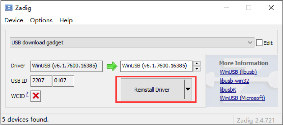
Execute the followings from the Windows command line using the host computer software
./dfu-util.exe -l
At this point the device will upload the partition table, which is defined in include/configs/evb_rv1126.h .
F:\Prj\20210901-Hisense-AB\dfu-util-0.9-win64>dfu-util.exe -l
dfu-util 0.9

Copyright 2005-2009 Weston Schmidt, Harald Welte and OpenMoko Inc.
Copyright 2010-2016 Tormod Volden and Stefan Schmidt
This program is Free Software and has ABSOLUTELY NO WARRANTY
Please report bugs to http://sourceforge.net/p/dfu-util/tickets/

Found DFU: [2207:0107] ver=0223, devnum=16, cfg=1, intf=0, path="1-12", alt=5,
name="userdata", serial="UNKNOWN"
Found DFU: [2207:0107] ver=0223, devnum=16, cfg=1, intf=0, path="1-12", alt=4,
name="rootfs", serial="UNKNOWN"
Found DFU: [2207:0107] ver=0223, devnum=16, cfg=1, intf=0, path="1-12", alt=3, name="boot",
serial="UNKNOWN"
Found DFU: [2207:0107] ver=0223, devnum=16, cfg=1, intf=0, path="1-12", alt=2, name="uboot",
serial="UNKNOWN"
Found DFU: [2207:0107] ver=0223, devnum=16, cfg=1, intf=0, path="1-12", alt=1,
name="loader", serial="UNKNOWN"
Found DFU: [2207:0107] ver=0223, devnum=16, cfg=1, intf=0, path="1-12", alt=0, name="gpt",
serial="UNKNOWN"
The Windows command line executes the following command to transfer files to the development board in the command line format dfu-util.exe VID:PID -a (partition name) -D (file name) -R (reboot option)
F:\Prj\20210901-Hisense-AB\dfu-util-0.9-win64>dfu-util.exe -d 2207:0107 -a system_b -D
rootfs.img -R
The log of a successful download is as follows
dfu-util 0.9

Copyright 2005-2009 Weston Schmidt, Harald Welte and OpenMoko Inc.
Copyright 2010-2016 Tormod Volden and Stefan Schmidt
This program is Free Software and has ABSOLUTELY NO WARRANTY
Please report bugs to http://sourceforge.net/p/dfu-util/tickets/

Invalid DFU suffix signature
A valid DFU suffix will be required in a future dfu-util release!!!
Opening DFU capable USB device...
ID 2207:0107
Run-time device DFU version 0110
Claiming USB DFU Interface...
Setting Alternate Setting #8 ...
Determining device status: state = dfuIDLE, status = 0
dfuIDLE, continuing
DFU mode device DFU version 0110
Device returned transfer size 4096
Copying data from PC to DFU device
Download        [=========================] 100%     49938432 bytes
Download done.
state(7) = dfuMANIFEST, status(0) = No error condition is present
state(2) = dfuIDLE, status(0) = No error condition is present
Done!
can't detach
Resetting USB to switch back to runtime mode
If you need to download other partitions, you only need to replace the partition name after the -a option of the download command and the file name after the -D option; the -R parameter appended to the download command indicates that the board will be rebooted after the download is completed.
4.7 DTBO/DTO
In order to facilitate the user’s understanding of the contents of this chapter, here we recommend you first read the Appendix Section to recognize the terminology: DTB, DTBO, DTC, DTO, DTS, FDT. The relationship between them can be described as: DTS is the file used to describe the FDT; DTS is compiled by DTC, can generate DTB/DTBO; DTB and DTBO can be combined into a new DTB through a DTO operation; Usually, many users are used to replace the action meaning of the word “DTO” with “DTBO”. In the following, to avoid this mixing concepts, we make it clear that DTO is a verb concept, which stands for operation; while DTBO is a noun concept, which refers to the number of dtb, indicating aggregation. More knowledge of this chapter can be found at: : https://source.android.google.cn/devices/architecture/dto.
4.7.1 Principle Introduction
DTO (Devcie Tree Overlay) is a mandatory feature introduced with Android P that allows a secondary device tree Blob (DTBO) to be overlayed on top of an existing primary device tree Blob. DTO maintains the system- on-chip SoC device tree and dynamically overlays device-specific device trees to add nodes to the tree and make changes to properties in the existing tree. The Primary Device Tree Blob (.dtb) is usually provided by the Vendor, while the Secondary Device Tree Blob (.dtbo) can be provided by ODM/OEM, etc., and finally merged by the bootloader before passing to the kernel. as shown in the figure below:
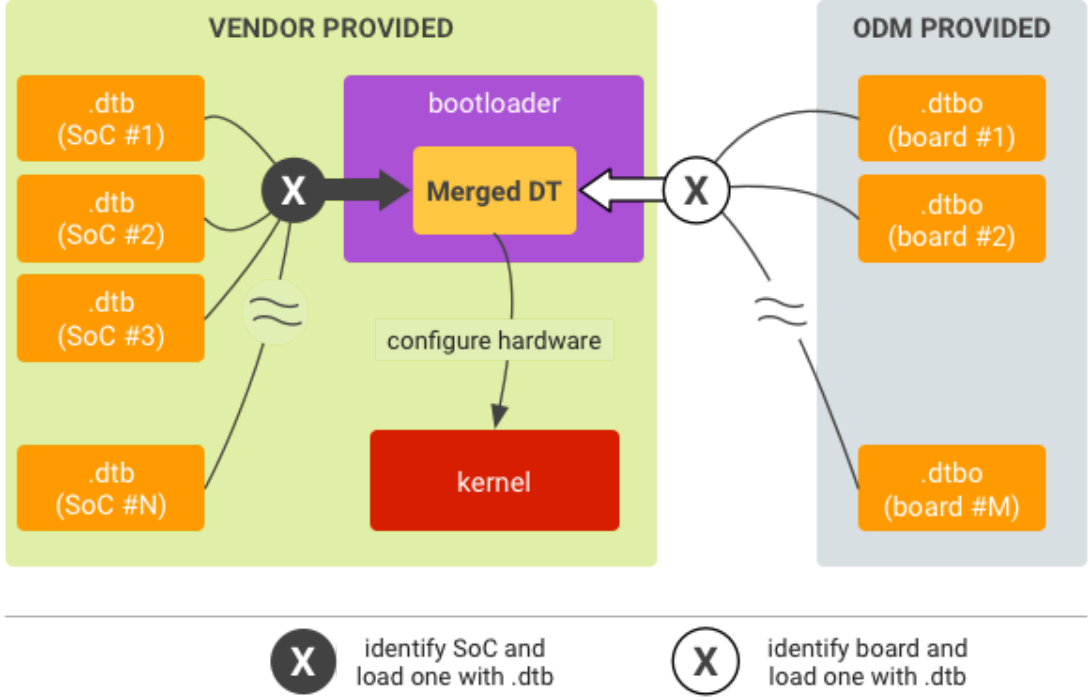
Image from: https://source.android.google.cn/devices/architecture/dto Note: The compilation of DTB and DTBO for DTO operations is different from the normal DTB compilation, and there is a special syntax difference: When compiling .dts with dtc, you must add the option -@ to add the symbols node to the resulting .dtbo. The symbols node contains a list of all nodes with labels that the DTO library can use the list as a reference. The following is an example:
- Sample commands for compiling the main .dts:
dtc -@ -O dtb -o my_main_dt.dtb my_main_dt.dts
- Sample commands for compiling the overlay DT .dts :
dtc -@ -O dtb -o my_overlay_dt.dtbo my_overlay_dt.dts
4.7.2 Enable DTO
- Configuration Enable:
CONFIG_CMD_DTIMG=y
CONFIG_OF_LIBFDT_OVERLAY=y
- Implementation of the board_select_fdt_index() function. This is a __weak function that can be reimplemented by the user. The function is to get the DTBO used to perform DTO operation among multiple DTBOs (return index index, the smallest starts from 0), the default weak function returns index
0.
/*
* Default return index 0.
*/
__weak int board_select_fdt_index(ulong dt_table_hdr)
{
    /*
     * User can use "dt_for_each_entry(entry, hdr, idx)" to iterate
     * over all dt entry of DT image and pick up which they want.
     *
     * Example:
     *  struct dt_table_entry *entry;
     *  int index;
     *
     *  dt_for_each_entry(entry, dt_table_hdr, index) {
     *
     *      .... (use entry)
     *  }
     *
     *  return index;
     */
    return 0;
}
4.7.3 DTO Result
- After DTO execution is complete, you can see the result in the boot message of U-Boot:
// The printout when it succeed
ANDROID: fdt overlay OK

// The printout when it failed
ANDROID: fdt overlay failed, ret=-19
Often the cause of failure is generally due to incompatibility between the contents of the primary/secondary device book blob, so the user needs to be clear about their generation syntax and compatibility.
- The following message is appended to the cmdline of the kernel after successful DTO execution,
indicating which DTBO is being used for the DTO operation:
androidboot.dtbo_idx=1  // The idx starts from 0. Here it means that the DTBO with idx=1 is
selected for DTO operation.
- After the DTO is successfully executed you can use the fdt command at the U-Boot command line to view the contents of the DTB to confirm that the changes have taken effect.
4.8 ENV
4.8.1 Framework Support
ENV is a very important data management method in U-Boot framework, which constructs “key value” and “data” through hash table for mapping management, and supports “add/delete/modify/check” operations. Usually, we call the keys and data it manages as environment variables.U-Boot supports saving ENV data in various storage media: NOWHERE/eMMC/FLASH/EEPROM/NAND/SPI_FLASH/UBI … configurations:
// Default configuration: ENV saved in memory
CONFIG_ENV_IS_NOWHERE

// ENV saved on various storage media
CONFIG_ENV_IS_IN_MMC
CONFIG_ENV_IS_IN_NAND
CONFIG_ENV_IS_IN_EEPROM
CONFIG_ENV_IS_IN_FAT
CONFIG_ENV_IS_IN_FLASH
CONFIG_ENV_IS_IN_NVRAM
CONFIG_ENV_IS_IN_ONENAND
CONFIG_ENV_IS_IN_REMOTE
CONFIG_ENV_IS_IN_SPI_FLASH
CONFIG_ENV_IS_IN_UBI

// Any storage media (except mmc) that has been accessed to the BLK framework layer is
recommended by the RK platform !
CONFIG_ENV_IS_IN_BLK_DEV
Framework code:
./env/nowhere.c
./env/env_blk.c
./env/mmc.c
./env/nand.c
./env/eeprom.c
./env/embedded.c
./env/ext4.c
./env/fat.c
./env/flash.c
......
4.8.2 Relevant Interface
// Getting Environment Variables
char *env_get(const char *varname);
ulong env_get_ulong(const char *name, int base, ulong default_val);
ulong env_get_hex(const char *varname, ulong default_val);

// Modify or create environment variables, value NULL is equivalent to deletion.
int env_set(const char *varname, const char *value);
int env_set_ulong(const char *varname, ulong value);
int env_set_hex(const char *varname, ulong value);

// Load all the ENV information saved on the storage media
int env_load(void);

// Save all current ENV information to a storage medium
int env_save(void);
env_load(): The user does not need to call it, the U-Boot framework will call it in the appropriate boot process; env_save(): User-initiated invocation at the moment of need will save all ENV information to the storage medium specified by CONFIG_ENV_IS_NOWHERE_XXX;
4.8.3 Advanced Interface
RK provides two high-level interfaces that unify the handling of ENVs with create, append, and replace functionality. This is primarily for handling bootargs environment variables, but is equally applicable to other environment variable operations.
/**
 * env_update() - update sub value of an environment variable
 *
 * This add/append/replace the sub value of an environment variable.
 *
 * @varname: Variable to adjust
 * @valude: Value to add/append/replace
 * @return 0 if OK, 1 on error
 */
int env_update(const char *varname, const char *varvalue);

/**
 * env_update_filter() - update sub value of an environment variable but
 * ignore some key word
 *
 * This add/append/replace/igore the sub value of an environment variable.
 *
 * @varname: Variable to adjust
 * @valude: Value to add/append/replace
 * @ignore: Value to be ignored that in varvalue
 * @return 0 if OK, 1 on error
 */
int env_update_filter(const char *varname, const char *varvalue, const char *ignore);
1 Rules for using env_update(): Create: creates varname and varvalue if varname does not exist; Append: append varvalue if varname already exists and varvalue does not; Replace: If varname already exists and varvalue already exists, replace the original with the current varvalue. For example: the original is “storagemedia=emmc”, the current input varvalue is “storagemedia=rknand”, then the final update will be “storagemedia=rknand”. rknand”. 2 env_update_filter() is an extended version of env_update(): it strips out a keyword from varvalue while updating env; 3 Special note: env_update() and env_update_filter() both use space and “=” as separator to split ENV content, so the unit of operation is: single word, “key=value” combination word: single word: sdfwupdate, …… “key=value”combination word: storagemedia=emmc, init=/init, androidboot.console=ttyFIQ0, …… The above two interfaces cannot handle long string units. For example, it is not possible to operate “console=ttyFIQ0 androidboot.baseband=N/A androidboot.selinux=permissive” as a whole unit.
4.8.4 Storage Location
env_save() saves the ENV to the storage medium. The storage location and size of the ENV for the RK platform are defined below:
if ARCH_ROCKCHIP
config ENV_OFFSET
    hex
    depends on !ENV_IS_IN_UBI
    depends on !ENV_IS_NOWHERE
    default 0x3f8000
    help
      Offset from the start of the device (or partition)
config ENV_SIZE
    hex
    default 0x8000
    help
      Size of the environment storage area
endif
Normally, neither ENV_OFFSET nor ENV_SIZE are recommended for modification.
4.8.5 General Options
Currently, the commonly used storage media are: eMMC/sdmmc/Nandflash/Norflash, etc. However, U-Boot’s native Nand and Nor ENV drivers all follow the MTD framework, while all the supported storage media in RK follow the BLK framework, so these ENV drivers cannot be used. Hence, RK provides the CONFIG_ENV_IS_IN_BLK_DEV configuration option for storage accessing the BLK framework For the eMMC/sdmmc case, select CONFIG_ENV_IS_IN_MMC ; For Nand, Nor case, select CONFIG_ENV_IS_IN_BLK_DEV; Users please first read the definition CONFIG_ENV_IS_IN_BLK_DEV of Kconfig
// It is already specified by default and does not need to be changed.
CONFIG_ENV_OFFSET
CONFIG_ENV_SIZE

// It won't be used usually.
CONFIG_ENV_OFFSET_REDUND (optional)
CONFIG_ENV_SIZE_REDUND (optional)
CONFIG_SYS_MMC_ENV_PART (optional)
Note: Whichever CONFIG_ENV_IS_IN_XXX configuration you choose, read the definition description in Kconfig first, which contains subconfiguration descriptions.
4.8.6 Fw_printenv Tool
fw_printenv is an env tool provided by U-Boot for linux. With this tool, users can access and modify the contents of env on linux. Using this tool requires that the env region be located on a kernel-visible partition (separate partitions are recommended), essentially accessing the env region through the storage node under the kernel sys. Tool Acquisition Methods:
./make.sh env
after executing the command, you will obtained :
./tools/env/fw_printenv      // env read/write tool
./tools/env/fw_env.config    // env configuration file
./tools/env/README           // env read/write tool documentation
Please refer to the README documentation for usage.
4.8.7 ENVF
This feature currently only applies to SDK firmware existed with env.img (mainly IPC-type products). If it does not exist, please ignore this section. U-Boot’s native ENV function is to save all environment variables to a specified storage area, which can be modified at will externally. If system-related variables are modified incorrectly, the system fail to boot normally, or be maliciously attacked. For example, the boot command bootcmd can be erased or pointed to a malicious boot process. Therefore, we have added the ENV Fragment function to separate U-Boot system environment variables from external user environment variables.
Users have to define an env fragment for storing customized environment variables and set up a whitelist in U-Boot, U-Boot only allows importing/exporting/modifying whitelisted environment variables from the env fragment. ENVF process: The user creates env.txt on demand and specifies the contents, then uses mkenvimage to generate and download env.img to storage 0 address. Loader and U-Boot load and parse the content of env.img at boot time, and import legal environment variables according to the CONFIG_ENVF_LIST whitelist. Where: for different storage types, different sizes of env.img need to be made. Configuration:
CONFIG_ENVF
CONFIG_SPL_ENVF
CONFIG_ENVF_LIST="blkdevparts mtdparts sys_bootargs app reserved"

// eMMC:
// Specifies the storage address of Primary env.img. Unit: bytes.
CONFIG_ENV_OFFSET=0x0
// Specifies the storage address of Backup env.img, which is the same as CONFIG_ENV_OFFSET
when there is no backup. Unit: bytes.
CONFIG_ENV_OFFSET_REDUND=0x0
// Size of Primary and Backup env.img. Unit: bytes.
CONFIG_ENV_SIZE=0x8000

// spi-nor: the same usage as above.
CONFIG_ENV_NOR_OFFSET=0x0
CONFIG_ENV_NOR_OFFSET_REDUND=0x0
CONFIG_ENV_NOR_SIZE=0x10000

// spi-nand/slc-nand: the same usage as above.
CONFIG_ENV_NAND_OFFSET=0x0
CONFIG_ENV_NAND_OFFSET_REDUND=0x0
CONFIG_ENV_NAND_SIZE=0x40000
Code:
./env/envf.c
Tools:
// By default, it participates in U-Boot compilation and generates tools/mkenvimage, which
is used to package env.img.
./tools/mkenvimage.c
PC development process (example)
- Creat env.txt:
// The system partition table must be defined or it will not boot properly. Example:
blkdevparts=mmcblk0:4M@8M(uboot),4M(trust),32M(boot),32M(recovery),32M(backup),-(rootfs)
sys_bootargs=rootwait earlycon=uart8250,mmio32,0xff570000 console=ttyFIQ0
......
Formatting requirements: (1) Use “key=value” key-value pairs. (2) “=” in key-value pairs: no spaces in left or right, no single/double quotes (3) Use newlines to indicate the end of a key-value pair sys_bootargs : The effect is equivalent to bootargs in kernel dts. if this field is specified, U-Boot will use sys_bootargs to overlay the bootargs in kernel dts, and sys_bootargs will have a higher priority when there are the same entries. Partition table: Support kernel-standard mtdparts and blkdevparts partition table format, please choose according to your needs (choose one). The partition formats for different storage are listed below:
// eMMC:
blkdevparts=mmcblk0:32K(env),512K@32K(idblock),256K(uboot),32M(boot),2G(rootfs),1G(oem),2G(u
serdata),-(media)

// spi-nor:
mtdparts=sfc_nor:64K(env),128K@64K(idblock),128K(uboot),2M(boot),4M(rootfs),6M(oem),-
(userdata)

// spi-nand/slc-nand:
mtdparts=rk-
nand:256K(env),256K@256K(idblock),256K(uboot),8M(boot),64M(rootfs),32M(userdata),-(media)
- Generate env.img:
## Chapter-4 eMMC:
./tools/mkenvimage -s 0x8000 -p 0x0 -o env.img env.txt

## Chapter-4 spi-nor:
./tools/mkenvimage -s 0x10000 -p 0x0 -o env.img env.txt

#spi-nand/slc-nand:
./tools/mkenvimage -s 0x40000 -p 0x0 -o env.img env.txt
-
env.img is downloaded to memory 0 address. U-Boot-side development process (example):
-
Enable and configure env.img on demand
// enable ENVF
CONFIG_ENVF=y
CONFIG_SPL_ENVF=y
CONFIG_ENVF_LIST="blkdevparts mtdparts sys_bootargs app reserved"

// eMMC:
CONFIG_ENV_SIZE=0x8000
CONFIG_ENV_OFFSET=0x0
CONFIG_ENV_OFFSET_REDUND=0x0

// spi nor:
CONFIG_ENV_NOR_OFFSET=0x0
CONFIG_ENV_NOR_OFFSET_REDUND=0x0
CONFIG_ENV_NOR_SIZE=0x10000

// spi nand/slc nand:
CONFIG_ENV_NAND_OFFSET=0x0
CONFIG_ENV_NAND_OFFSET_REDUND=0x0
CONFIG_ENV_NAND_SIZE=0x40000
-
Recompile and download uboot.img.
-
Power-on message display
......
dwmmc@ffc50000: 0, dwmmc@ffc60000: 1
Bootdev(atags): mmc 0
MMC0: HS200, 200Mhz
// printout as follows:
ENVF: Primary 0x00000000 - 0x00008000
ENVF: OK
PartType: ENV
DM: v1
boot mode: normal
FIT: no signed, no conf required
DTB: rk-kernel.dtb
......
- The user can save env from the U-Boot command line with the following command, or use code env_save()
=> env save
Saving Environment to env...  // Exporting and saving whitelisted environment variables
4.9 Fastboot
Fastboot is a way provided by Android to interact with U-Boot via USB, which is generally used for getting device information, downloading firmware, etc.
4.9.1 Configuration Options
// Enabled Configuration
CONFIG_FASTBOOT
CONFIG_FASTBOOT_FLASH
CONFIG_USB_FUNCTION_FASTBOO

// Parameter Configuration
CONFIG_FASTBOOT_BUF_ADDR
CONFIG_FASTBOOT_BUF_SIZE
CONFIG_FASTBOOT_FLASH_MMC_DEV
CONFIG_FASTBOOT_USB_DEV
4.9.2 Trigger Method
Fastboot uses Google adb’s VID/PID by default, with the following trigger methods: Command line execution of the kernel: reboot fastboot Command line execution of U-Boot: fastboot usb 0 Power on and long press combination-key : ctrl+f
4.9.3 Command Support
fastboot flash < partition > [ < filename > ]
fastboot erase < partition >
fastboot getvar < variable > | all
fastboot set_active < slot >
fastboot reboot
fastboot reboot-bootloader
fastboot flashing unlock
fastboot flashing lock
fastboot stage [ < filename > ]
fastboot get_staged [ < filename > ]
fastboot oem fuse at-perm-attr-data
fastboot oem fuse at-perm-attr
fastboot oem at-get-ca-request
fastboot oem at-set-ca-response
fastboot oem at-lock-vboot
fastboot oem at-unlock-vboot
fastboot oem at-disable-unlock-vboot
fastboot oem fuse at-bootloader-vboot-key
fastboot oem format
fastboot oem at-get-vboot-unlock-challenge
fastboot oem at-reset-rollback-index
4.9.4 Command Details
fastboot flash < partition > [ < filename > ] Function: Partition download Example: fastboot flash boot boot.img fastboot erase < partition > Function: Erase Partition Example: fastboot erase boot fastboot getvar < variable > Function: Get device information Example: fastboot getvar version-bootloader < variable > parameters:
version                               /* fastboot version */
version-bootloader                    /* uboot version */
version-baseband
product                               /* Product Information */
serialno                              /* sertial number */
secure                                /* security checking enabled or not*/
max-download-size                     /* the maximum number of bytes supported by
fastboot in a single transfer */
logical-block-size                    /* Number of logical blocks */
erase-block-size                      /* Number of erased blocks */
partition-type : < partition >        /* Partition type*/
partition-size : < partition >        /* Partition size */
unlocked                              /* Device lock status */
off-mode-charge
battery-voltage
variant
battery-soc-ok
slot-count                            /* Number of slots*/
has-slot: < partition >               /* Check if the partition name is in the slot
*/
current-slot                          /* Currently booted slots*/
slot-suffixes                         /* The current slot of the device, print its
name. */
slot-successful: < _a | _b >          /* See if the partition is properly verified and
booted*/
slot-unbootable: < _a | _b >          /* Check if the partition is set to unbootable
*/
slot-retry-count: < _a | _b >         /* Check the number of retry-counts for a
partition */
at-attest-dh
at-attest-uuid
at-vboot-state
fastboot getvar all Function: Get all device information fastboot set_active < slot > Function: Set the slot for reboot Example: fastboot set_active _a fastboot reboot Function: Reboot the device for normal startup Example: fastboot reboot fastboot reboot-bootloader Function: Reboot the device to enter fastboot mode.
Example: fastboot reboot-bootloader fastboot flashing unlock Function: Unlock the device and allow firmware downloading Example: fastboot flashing unlock fastboot flashing lock Function: Lock the device, prohibit downloading Example: fastboot flashing lock fastboot stage [ < filename > ] Function: Download data to device-side memory, the memory start address is CONFIG_FASTBOOT_BUF_ADDR.
Example: fastboot stage permanent_attributes.bin fastboot get_staged [ < filename > ] Function: Getting data from the device side Example: fastboot get_staged raw_unlock_challenge.bin fastboot oem fuse at-perm-attr Function: Download permanent_attributes.bin and hash.
Example: fastboot stage permanent_attributes.bin fastboot oem fuse at-perm-attr
fastboot oem fuse at-perm-attr-data Function: Download only permanent_attributes.bin to the secure storage area (RPMB) Example: fastboot stage permanent_attributes.bin fastboot oem fuse at-perm-attr-data fastboot oem at-get-ca-request fastboot oem at-set-ca-response fastboot oem at-lock-vboot Function: Lock device Example: fastboot oem at-lock-vboot fastboot oem at-unlock-vboot Function: Unlock the device, now support authenticated unlock Example: fastboot oem at-get-vboot-unlock-challenge fastboot get_staged raw_unlock_challenge.bin ./make_unlock.sh (See make_unlock.sh for reference) fastboot stage unlock_credential.bin fastboot oem at-unlock-vboot You can refer to “how-to-generate-keys-about-avb.md”. fastboot oem fuse at-bootloader-vboot-key Function: Download bootloader key hash Example: fastboot stage bootloader-pub-key.bin fastboot oem fuse at-bootloader-vboot-key fastboot oem format Function: reformat partitions, partition information depends on $partitions Example: fastboot oem format fastboot oem at-get-vboot-unlock-challenge Function: authenticated unlock, need to get unlock challenge data Example: please refer to 16. fastboot oem at-unlock-vboot fastboot oem at-reset-rollback-index Function: Reset the rollback data of the device Example: fastboot oem at-reset-rollback-index fastboot oem at-disable-unlock-vboot Function: Disables the fastboot oem at-unlock-vboot command.
Example: fastboot oem at-disable-unlock-vboot
4.10 FileSystem
4.10.1 Framework Support
FAT and EXT2/4 are commonly used file system formats. Among them, FAT uses DOS (MBR) partition table, and the common devices are: SD card, USB flash drive. These two file systems are generally accessed more often in U-Boot today. FAT configuration:
CONFIG_DOS_PARTITION=y
CONFIG_FS_FAT=y
CONFIG_FAT_WRITE=y
CONFIG_FS_FAT_MAX_CLUSTSIZE=65536
CONFIG_CMD_FAT=y
CONFIG_CMD_FS_GENERIC=y
FAT command:
fatinfo fatload fatls fatsize fatwrite
EXT2/4 configuration:
CONFIG_CMD_EXT2=y
CONFIG_CMD_EXT4=y
CONFIG_CMD_FS_GENERIC=y
EXT2/4 command:
ext2load ext2ls ext4load ext4ls ext4size
4.10.2 Relevant Interface
FAT function header file . /include/fat.h:
int file_fat_detectfs(void);
int fat_exists(const char *filename);
int fat_size(const char *filename, loff_t *size);
int file_fat_read_at(const char *filename, loff_t pos, void *buffer,
             loff_t maxsize, loff_t *actread);
int file_fat_read(const char *filename, void *buffer, int maxsize);
int fat_set_blk_dev(struct blk_desc *rbdd, disk_partition_t *info);
int fat_register_device(struct blk_desc *dev_desc, int part_no);

int file_fat_write(const char *filename, void *buf, loff_t offset, loff_t len,
           loff_t *actwrite);
int fat_read_file(const char *filename, void *buf, loff_t offset, loff_t len,
          loff_t *actread);
int fat_opendir(const char *filename, struct fs_dir_stream **dirsp);
int fat_readdir(struct fs_dir_stream *dirs, struct fs_dirent **dentp);
void fat_closedir(struct fs_dir_stream *dirs);
void fat_close(void);
EXT2/4 function header file include/ext4fs.h:
struct ext_filesystem *get_fs(void);
int ext4fs_open(const char *filename, loff_t *len);
int ext4fs_read(char *buf, loff_t offset, loff_t len, loff_t *actread);
int ext4fs_mount(unsigned part_length);
void ext4fs_close(void);
void ext4fs_reinit_global(void);
int ext4fs_ls(const char *dirname);
int ext4fs_exists(const char *filename);
int ext4fs_size(const char *filename, loff_t *size);
void ext4fs_free_node(struct ext2fs_node *node, struct ext2fs_node *currroot);
int ext4fs_devread(lbaint_t sector, int byte_offset, int byte_len, char *buf);
void ext4fs_set_blk_dev(struct blk_desc *rbdd, disk_partition_t *info);
long int read_allocated_block(struct ext2_inode *inode, int fileblock);
int ext4fs_probe(struct blk_desc *fs_dev_desc,
         disk_partition_t *fs_partition);
int ext4_read_file(const char *filename, void *buf, loff_t offset, loff_t len,
           loff_t *actread);
int ext4_read_superblock(char *buffer);
int ext4fs_uuid(char *uuid_str);
4.10.3 Example of Command
// Confirm that the SD card is recognizable(if it is a USB flash drive then use the usb
command for recognition, the device number is usually: usb 0)
=> mmc dev 1
switch to partitions #0, OK
mmc1 is current device

// View Information
=> fatinfo mmc 1
Interface:  MMC
  Device 1: Vendor: Man 000003 Snr e81ec501 Rev: 1.9 Prod: SC16G
  Type: Removable Hard Disk
  Capacity: 15193.5 MB = 14.8 GB (31116288 x 512)
Filesystem: FAT32 "NO NAME    "

// View File
=> fatls mmc 1
            System Volume Information/
       23   hello.txt
       23   linux.txt
2 file(s), 1 dir(s)

// Read the size of the hello.txt file (the result is saved to the variable filesize by
default)
=> fatsize mmc 1 hello.txt
=> echo $filesize
0x17

// Read hello.txt file to address 0x2000000
=> fatload mmc 1 0x2000000 hello.txt
reading hello.txt
23 bytes read in 2 ms (10.7 KiB/s)
// Viewing the contents of read hello.txt
=> md.l 0x2000000
02000000: 6c6c6568 65682d6f 2d6f6c6c 6c6c6568    hello-hello-hell
02000010: 65682d6f ff6f6c6c ffffffff ffffffff    o-hello.........

// Create a new file: hello-copy.txt. Write the contents of addresses 0x2000000~0x2000017 to
hello-copy.txt.
=> fatwrite mmc 1 0x2000000 hello-copy.txt 0x17
writing hello-copy.txt
23 bytes written
// See new file: hello-copy.txt
=> fatls mmc 1
            System Volume Information/
       23   hello.txt
       23   linux.txt
       23   hello-copy.txt

3 file(s), 1 dir(s)
Note: The ext2/4 and fat commands are used in a similar way, so no specific instructions are given.
4.11 HW-ID DTB
The U-Boot of RK platform supports detecting the GPIO or ADC status on the hardware to dynamically load different Kernel DTBs, which is tentatively called HW-ID DTB (Hardware id DTB) function.
4.11.1 Design Principle
Usually the hardware design is frequently updated with newer versions and components, such as screen, wifi module, etc. If each hardware version has to correspond to a set of software, it will be troublesome to maintain it. So we need the HW_ID function to realize that a set of software can be adapted to different versions of hardware. For different hardware versions, the software needs to provide the corresponding dtb file, as well as the ADC/GPIO hardware unique values to characterize the current hardware version (e.g., a fixed adc value, a fixed GPIO level).
The user packages all these dtb files corresponding to the hardware version into a same resource.img. When U-Boot boots the kernel, it checks for hardware uniqueness and finds the dtb that matches the current hardware version from the resource.img and passes it to the kernel.
4.11.2 Hardware Reference
Both ADC and GPIO are currently supported to determine the hardware version. ADC reference design The RK3326-EVB/PX30-EVB motherboard has reserved voltage divider resistors, different resistor divider has different ADC value, so that you can determine the different hardware versions:.
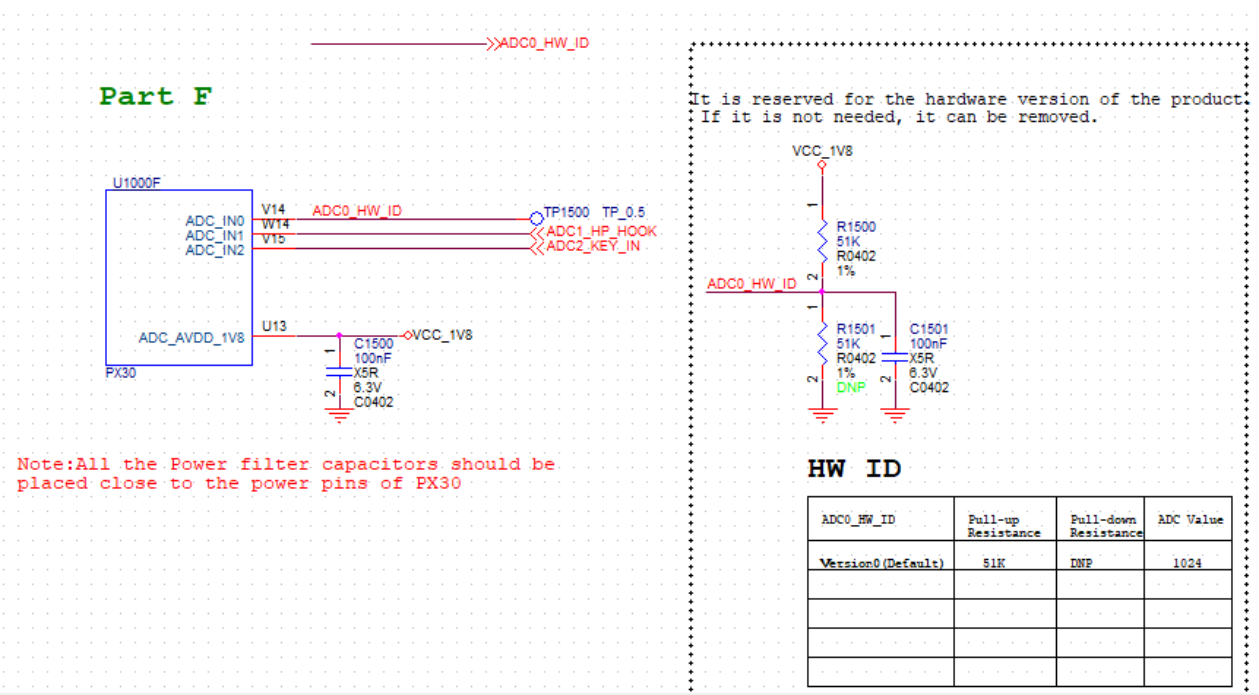
The MIPI panel is equipped with an additional pull-down resistor.
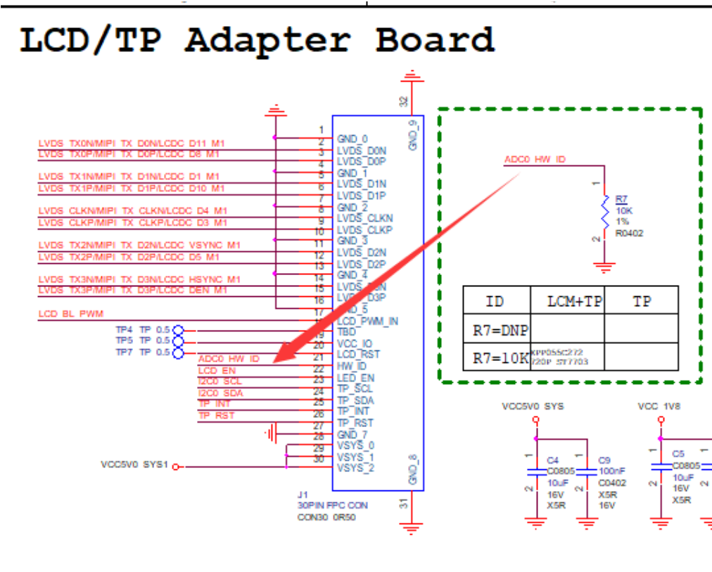
Different mipi screens will be configured with different resistance values, and a unique ADC parameter value will be determined in conjunction with the EVB motherboard. ADC calculation method for current V1 version: the maximum value of the ADC parameter is 1024, which corresponds to the ADC_IN0 pin being pulled up directly to the supply voltage of 1.8V, and there is a 10K pull- down resistor on the MIPI screen, after successful connecting to the EVB board, the ADC = 1024*10K/(10K + 51K) = 167.8 . GPIO reference design There is currently no hardware reference design for GPIOs, which can be customized by the user.
4.11.3 DTB Naming
Users need to reflect the hardware unique value information of ADC/GPIO in the dtb file name. The naming convention is as follows: ADC as HW_ID DTB: The file name ends with “.dtb”; HW_ID format: #[controller]_ch[channel]=[adcval], called a complete unit : The node name of the ADC controller inside dts. : ADC channel. : The center value of the ADC, the actual valid range is: adcval+-30. Each complete unit must be in lowercase letters with no internal spaces; Multiple units are separated by #, up to 10 units are supported.;
Example:
rk3326-evb-lp3-v10#saradc_ch2=111#saradc_ch1=810.dtb
rk3326-evb-lp3-v10#_saradc_ch2=569.dtb
GPIO as HW_ID DTB: The file name ends with “.dtb”; HW_ID format: #gpio[pin]=[level], called a complete unit : GPIO pin, e.g. 0a2 for gpio0a2 : GPIO Pin Levels. Each complete unit must be in lowercase letters with no internal spaces; Multiple units are separated by #, up to 10 units are supported.; Example:
rk3326-evb-lp3-v10#gpio0a2=0#gpio0c3=1.dtb
4.11.4 DTB Packaging
kernel repository: scripts/mkmultidtb.py. This script can be used to package multiple dtbs into the same resource.img. The user needs to open the script file to write the dtb file to be packed into the DTBS dictionary and fill in the corresponding ADC/GPIO configuration information.
...
DTBS = {}
DTBS['PX30-EVB'] = OrderedDict([('rk3326-evb-lp3-v10', '#_saradc_ch0=166'),
                ('px30-evb-ddr3-lvds-v10', '#_saradc_ch0=512')])
...
In the above example, executing scripts/mkmultidtb.py PX30-EVB generates resource.img with 3 copies of the dtb: rk-kernel.dtb: rk’s default dtb, not reflected in the above dictionary. It is used by default when all dtb’s are not matched successfully. The packaging script will use the first dtb of the DTBS as the default dtb; rk3326-evb-lp3-v10#_saradc_ch0=166.dtb: The rk3326 dtb file containing ADC information; px30-evb-ddr3-lvds-v10#_saradc_ch0=512.dtb: The px30 dtb file containing ADC information; If you run scripts/mkmultidtb.py manually, you will also need manually replace the generated resource.img into boot.img. For convenience, the user can increase the calls like follows, and the compilation of the kernel repository will automatically include the multi-DTB resource.img.
diff --git a/scripts/mkimg b/scripts/mkimg
index 1d895602935..5e1355b9da8 100755
--- a/scripts/mkimg
+++ b/scripts/mkimg
@@ -248,6 +248,7 @@ if [ "${srctree}" != "${objtree}" ]; then
 fi
 scripts/resource_tool ${DTB_PATH} ${LOGO} ${LOGO_KERNEL} >/dev/null
 echo "  Image:  resource.img (with ${DTB} ${LOGO} ${LOGO_KERNEL}) is ready"
+./scripts/mkmultidtb.py PX30-EVB

 if [ -f "${BOOT_IMG}" ]; then
        if file -L -p -b ${BOOT_IMG} | grep -q 'Device Tree Blob' ; then
4.11.5 Feature Enablement
Configuration options:
CONFIG_ROCKCHIP_HWID_DTB=y
Driver code:
./arch/arm/mach-rockchip/resource_img.c // Specific realization: rockchip_read_hwid_dtb()
DTS configuration: If GPIOs are used as hardware identification, the corresponding pinctrl and gpio nodes must be reserved in rkxx-u-boot.dtsi; ADCs are enabled by default. For example, gpio0 and gpio1 are used as identification:
...

&pinctrl {
    u-boot,dm-spl;  // Append this attribute to allow the node to be retained in the U-Boot
DTB. Same below.
};

&gpio0 {
    u-boot,dm-spl;
};

&gpio1 {
    u-boot,dm-spl;
};

...
4.11.6 Load Results
......
mmc0(part 0) is current device
boot mode: None
DTB: rk3326-evb-lp3-v10#_saradc_ch0=166.dtb // Prints the matching DTB, otherwise defaults
to “rk-kernel.dtb”.
Using kernel dtb
......
4.12 SD and USB Flash Drives
This chapter focuses on firmware booting and upgrading of SD and USB flash drives on the RK platform.
4.12.1 Mechanisms and Principles
After the boot card and upgrade card are created, a fixed tag is placed in the firmware header at a fixed storage offset location to mark whether it is a boot card or an upgrade card. U-Boot recognizes this tag and proceeds with the corresponding boot or upgrade process. where: Boot Card: There is only one complete firmware in the card, U-Boot uses this complete firmware to directly boot the system normally; Upgrade card: The card contains two copies of firmware. When creating an upgrade card, the PC tool will write two copies of firmware: one of which containing only the partition image necessary to enter recovery mode (denoted as firmware A), and the other on containing with the complete update.img firmware (denoted as firmware B). U-Boot uses firmware A to boot the system into recovery mode, and then the recovery program uses firmware B to complete the upgrade work. Special Notes: SD card boot/upgrade is supported from the bootrom level; USB disk boot/upgrade is only supported from the U-Boot level, which means that the user should at least make sure that U-Boot is working properly!
4.12.2 Firmware Creation
The process of creating SD and USB disk boot cards and upgrade cards on the RK platform is identical and requires only two steps: Use the RKTools/linux/Linux_Pack_Firmware/rockdev/ tool in the SDK directory to generate update.img. Use SDDiskTool to download update.img to SD or USB disk. As shown in the picture: Select removable disks Select Firmware Upgrade or SD Boot .
Click Start Creating
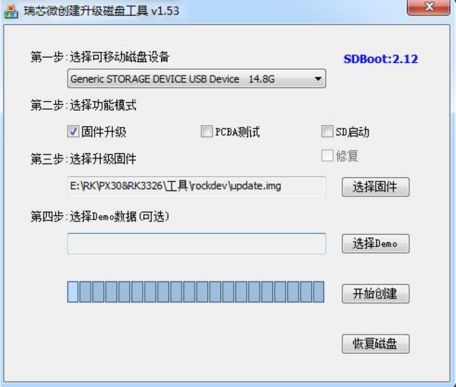
4.12.3 SD Configuration
SD Boot/Upgrade: U-Boot released by SDK of each platform has enabled this function by default, users do not need to configure it additionally.
4.12.4 USB Configuration
USB Boot/Upgrade: U-Boot released by each platform SDK is not enabled by default. Because U-Boot’s native USB scanning command is time-consuming, it’s better for users enabling it themselves on demand: Step 1: download the upgrade firmware to local storage (eMMC/Nand/…etc.), make sure the firmware is available.
Step 2: Plug in the USB flash drive and boot into U-Boot command line mode. Execute usb start and usb info commands to make sure the USB flash drive is recognized normally, otherwise, please adjust the USB flash drive recognition first.
Step 3: Make a copy of the kernel DTB that alighed with step 1 and name it kern.dtb and put it in U- Boot’s . /dts/ directory of U-Boot. This kern.dtb will be automatically packed into uboot.img when compiling U-Boot. kern.dtb Purpose: U-Boot uses kern.dtb to ensure that the USB is initialized properly when the kernel dtb of the local storage partition is corrupted.
Step 4: U-Boot enable boot/upgrade configuration of USB
CONFIG_ROCKCHIP_USB_BOOT=y
Recompile and download uboot.img. If the process prompts that uboot’s firmware is too large to be packaged and resulted from the addition of kern.dtb in step 3, please cut out some unused U-Boot configurations first.
4.12.5 Functions Taking Effect
How to confirm that the SD, USB disk boot or upgrade function is in effect.
Users can erase key partitions such as kernel, resource, boot, recovery on local storage (eMMC, Nand…) to make sure you can enter kernel after inserting SD/U disk.
4.12.6 Notes
The usb start command is called when the USB flash drive is initialized, and the whole process is relatively time-consuming; If the boot/upgrade card needs to support GPT partition tables, the version of the SDDiskTool tool requires >= v1.59; If the boot/upgrade card needs to support AB systems, the version of the SDDiskTool tool requires >= v1.61 Because the USB disk boot/upgrade feature is a feature added in 2019.11, the relevant repository needs to meet the following conditions
- U-Boot repository shall be updated to the following commit points (recommended)
commit 369e944c844f783508b7839ae86a3418e2f63bc7
Author: Joseph Chen <chenjh@rock-chips.com>
Date:   Thu Dec 12 18:07:07 2019 +0800

    fdt/Makefile: make u-boot-dtb.bin 8-byte aligned

    The dts/kern.dtb is appended after u-boot-dtb.bin for U-disk boot.

    Make sure u-boot-dtb.bin is 8-byte aligned to avoid data-abort on
    calling: fdt_check_header(gd->fdt_blob_kern).

    Signed-off-by: Joseph Chen <chenjh@rock-chips.com>
    Change-Id: Id5f2daf0c5446e7ea828cb970d3d4879e3acda86
Or add the following patch changes individually (presumably more difficult):
369e944 fdt/Makefile: make u-boot-dtb.bin 8-byte aligned
b3b57ac rockchip: board: fix always entering recovery on normal boot U-disk
e0cee41 rockchip: resource: add sha1/256 verify for kernel dtb
5e817a0 tools: rockchip: resource_tool: add sha1 for file entry
fc474da lib: sha256: add sha256_csum()
0ed06f1 rockchip: support boot from U-disk
01f0422 common: bootm: skip usb_stop() if usb is boot device
5704c89 fdtdec: support pack "kern.dtb" to the end of u-boot.bin
3bdef7e gpt: return 1 directly when test the mbr sector
- The rkbin repository should contain this commit:
commit f9c0b0b72673a65865b00a8824908ca6f12ecc32
Author: Joseph Chen <chenjh@rock-chips.com>
Date:   Thu Nov 7 09:21:36 2019 +0800

    tools: resource: add sha1 for file entry

    Base on U-Boot next-dev branch:
    (5e817a0 tools: rockchip: resource_tool: add sha1 for file entry)

    Change-Id: Ife061cabacab488dbecf2a3245d58cc660091dbd
    Signed-off-by: Joseph Chen <chenjh@rock-chips.com>
- The kernel repository should contain this commit:
commit 078785057478c789bb033ba06925fa3a07e3130a
Author: Tao Huang <huangtao@rock-chips.com>
Date:   Thu Nov 7 17:53:38 2019 +0800

    rk: scripts/resource_tool: add sha1 for file entry

    From u-boot 5e817a0ea427 ("tools: rockchip: resource_tool: add sha1 for file
entry").
    Merge all C files to one resource_tool.c

    Change-Id: If63ba77d1f5a3660bd6ef87769bb456fa086ae71
    Signed-off-by: Tao Huang <huangtao@rock-chips.com>
If the SDK owned by the user is relatively old, in addition to adding the above patches individually, it is recommended to check with the engineer in charge of recovery to see if recovery has the relevant patches.
5. Chapter-5 Driver Module
5.1 AMP
5.1.1 Ideas for Implementation
The U-Boot framework does not have AMP (Asymmetric Multi-Processing) support by default, however, RK implements a set of AMP mechanism by itself: different CPUs run different firmware. Implementation Ideas: (1) Firmware Packaging All AMP firmware (excluding Linux) specifies the CPU running state, describes the firmware information through its file, and finally packages it into a FIT-formatted amp.img to be downloaded to the amp partition. During booting, U-Boot is responsible for loading the amp.img firmware and performing sha256 integrity checks, and then trust specifies the running state of each CPU and dispatches it to the corresponding entry address. (2) Boot order The CPU running U-Boot is called the master core, which finally operates on itself after completing state switching and firmware jumps of other cores. (3) Resource management U-Boot is not responsible for the coordination of resources (including the division of memory, interrupts, etc.) between firmwares under the AMP scheme, so developers please make sure for it. (4) Trust support The AMP feature requires trust support. If the user-specified CPU running state is the default state, then the SDK’s trust is already supported; if it is not the default state, then trust requires additional support (but some platforms’ SDKs already support it by default). The above CPU default state refers to: 32-bit chip default state: arch = “arm”, thumb = <0>, hyp = 0; 64-bit chip default state: arch = “arm64”, thumb = <0>, hyp = 1; (5) Linux+AMP combination
-
Considering the compatibility, the Linux-related firmware under the combination scheme is consistent with the traditional SMP firmware, i.e. Linux-related firmware + amp.img.
-
Developers can specify the state of the CPU running Linux by adding a “linux” node to amp’s its (without it, it’s the default state).
-
If the main core is running Linux or no firmware is specified, the main core will boot Linux from U-Boot in the traditional SMP boot fashion after booting other AMP firmware.
-
If the non-main core is running Linux, boot Linux first, then other AMP firmware.
Note: If you want to boot on a core other than CPU0, you need special trust support.
- The load address of the Linux firmware is determined by the U-Boot configuration only, e.g. rk3568_common.h.
5.1.2 Framework Support
Configurations:
CONFIG_AMP
CONFIG_ROCKCHIP_AMP
Framework Code:
./drivers/cpu/rockchip_amp.c
its templates:
./drivers/cpu/amp.its
Packing Tools:
./tools/mkimage // wil be generated automatically after a full U-Boot compilation
Code commit point at least includes:
commit c51cf04095dde2df2dd047e70d2c7fb0866ea916
Author: Joseph Chen <chenjh@rock-chips.com>
Date:   Tue Oct 19 03:16:35 2021 +0000

    cpu: amp.its: update amps "arm64" => "arm"

    Signed-off-by: Joseph Chen <chenjh@rock-chips.com>
    Change-Id: I99de02c5b6c62ffdd9b25565acd172801d6e983c
5.1.3 Feature Enablement
- To create amp.img you need an its file, please modify it based on drivers/cpu/amp.its : The following its: CPU1/2/3 runs AMP, CPU0 runs Linux, and the main core is CPU3. The boot order is: CPU0 => CPU1/2 => CPU3.
/dts-v1/;
/ {
    description = "FIT source file for rockchip AMP";
    #address-cells = <1>;
    // All AMP firmware (excluding Linux) should be specified under the images node;
    images {
        amp1 {
            description  = "bare-mental-core1";       // Required: Description info
            data         = /incbin/("./amp1.bin");    // Required: amp1 firmware
            type         = "firmware";  // Required: No change
            compression  = "none";      // Required: No change
            arch         = "arm";       // Required: “arm64”: 64-bit, “arm”: 32-bit
            cpu          = <0x100>;     // Required: cpu hardware id (mpidr)
            thumb        = <0>;         // Required: 0: arm or thumb2; 1: pure thumb
            hyp          = <0>;         // Required: 0: el1/svc; 1: el2/hyp
            load         = <0x01800000>;// Required: Firmware load and run address
            udelay       = <1000000>;   // Optional: delay after booting the current CPU and
then start the next CPU.
            hash {                      // Required: No change
                algo = "sha256";
            };
        };

        amp2 {
            description  = "bare-mental-core2";
            data         = /incbin/("./amp2.bin");
            type         = "firmware";
            compression  = "none";
            arch         = "arm";
            cpu          = <0x200>;
            thumb        = <0>;
            hyp          = <0>;
            load         = <0x03800000>;
            udelay       = <1000000>;
            hash {
                algo = "sha256";
            };
        };

        amp3 {
            description  = "bare-mental-core3";
            data         = /incbin/("./amp3.bin");
            type         = "firmware";
            compression  = "none";
            arch         = "arm";
            cpu          = <0x300>;
            thumb        = <0>;
            hyp          = <0>;
            load         = <0x05800000>;
            udelay       = <1000000>;
            hash {
                algo = "sha256";
            };
        };
    };

    configurations {
        default = "conf";
        conf {
            description = "Rockchip AMP images";
            rollback-index = <0x0>;
            // Specifies the firmware to be loaded and the order in which it should be
loaded and booted, but the master core is not subject to this order.
            loadables = "amp1", "amp2", "amp3";

            signature {
                algo = "sha256,rsa2048";
                padding = "pss";
                key-name-hint = "dev";
                sign-images = "loadables";
            };

            // Linux CPU runtime state designation:
            // (1) Only the udelay attribute is optional;
            // (2) The boot address is not assignable and is determined by U-Boot's platform
configuration file, e.g.: rk3568_common.h;
            linux {
                description  = "linux-os";
                arch         = "arm64";
                cpu          = <0x000>;    // CPU0 runs linux
                thumb        = <0>;
                hyp          = <0>;
                udelay       = <1000000>;
            };
        };
    };
};
Notes: description: Description information.. type: The default is “firmware”. compression: The default is “none”. data: Firmware path. The path is a relative path based on amp.its. arch: CPU 32/64 mode: ARMv7 can only be specified as “arm”; ARMv8 can be specified as “arm64” or “arm”, which means AArch64 or AArch32 respectively. cpu: CPU hardware ID, i.e. mpidr (Multiprocessor Affinity Register), take the lower 32 bits. For example:
cpus {
    #address-cells = <2>;
    #size-cells = <0>;

    cpu0: cpu@0 {
        device_type = "cpu";
        compatible = "arm,cortex-a55";
        reg = <0x0 0x0>;    // mpidr
        ......
    };

    cpu1: cpu@100 {
        device_type = "cpu";
        compatible = "arm,cortex-a55";
        reg = <0x0 0x100>;  // mpidr
        ......
    };
    ......
};
thumb: CPU instruction mode. Specify 1 if pure THUMB, 0 otherwise. hyp: CPU VM mode. load: Firmware load and run address udelay: Delay after completion of boot (optional), in us. After booting the current CPU, do the corresponding delay before booting the next CPU. loadables: The AMP firmware to be loaded and the order in which it is loaded and booted. The main CPU must be the last to be booted and is not subject to the order here. linux node: For Linux + AMP combination programs. Please refer to the “Ideas for Implementation” in this section.
- Firmware packing:
// 0xe00 is the firmware header size and is not recommended to be changed
./tools/mkimage -f ./drivers/cpu/amp.its -E -p 0xe00 amp.img
A full compilation of U-Boot is required to automatically generate the mkimage tool.
-
Add amp partition to partition table Add the “amp” partition to the parameter.txt partition table file and then download amp.img. U-Boot is to directly load the contents of the entire amp partition into memory, so it is recommended that the amp partition size is configured according to actual needs
-
Bring up The U-Boot framework will automatically initiate the bring up of all AMPs at the right time. The following is the boot information of CPU3 running AMP firmware as the main core and CPU0/1/2 running Linux firmware:
......
// the master core loading firmware amp3 firmware
### Loading loadables from FIT Image at 7bdbcf80 ...
   Trying 'amp3' loadables subimage
     Description:  rtthread
     Type:         Firmware
     Compression:  uncompressed
     Data Start:   0x7bdbdd80
     Data Size:    311296 Bytes = 304 KiB
     Architecture: ARM
     Load Address: 0x01800000
     Hash algo:    sha256
     Hash value:   d08db937e4d7bd4125056239154bb30d44a2fcca9e70aa8dea448fabda4838d5
   Verifying Hash Integrity ... sha256+ OK
   Loading loadables from 0x7bdbdd80 to 0x01800000
### Booting FIT Image FIT: No fit blob
FIT: No FIT image
ANDROID: reboot reason: "(none)"
optee api revision: 2.0
TEEC: Waring: Could not find security partition
Not AVB images, AVB skip
ANDROID: Hash OK

// the master core loading Linux firmware
Booting IMAGE kernel at 0x03880000 with fdt at 0x0a100000...

Fdt Ramdisk skip relocation
### Booting Android Image at 0x0387f800 ...
Kernel load addr 0x03880000 size 21655 KiB
### Flattened Device Tree blob at 0x0a100000
   Booting using the fdt blob at 0x0a100000
   XIP Kernel Image from 0x03880000 to 0x03880000 ... OK
  'reserved-memory' ramoops@110000: addr=110000 size=f0000
   Using Device Tree in place at 000000000a100000, end 000000000a12322a
vp1 adjust cursor plane from 0 to 1
vp0, plane_mask:0x2a, primary-id:5, curser-id:1
vp1 adjust cursor plane from 1 to 0
vp1, plane_mask:0x15, primary-id:4, curser-id:0
vp2, plane_mask:0x0, primary-id:0, curser-id:-1
Adding bank(fixed): 0x03880000 - 0x80000000 (size: 0x7c780000)

// At this point, all the firmware is loaded, and it starts to boot each CPU according to
the program's prioritization rules,as follows

// The main core boots CPU0 to run Linux (CPU1/2 subsequently boots via Linux)
AMP: Brought up cpu[0] with state 0x12, entry 0x03880000 ...OK
// The main core boots itself (CPU3) to run the AMP firmware
AMP: Brought up cpu[300, self] with state 0x10, entry 0x01800000 ...OK

// Linux runs on CPU0:
[    0.000000] Booting Linux on physical CPU 0x0000000000 [0x412fd050]
[    0.000000] Linux version 4.19.193 (stevenliu@stevenliu) (gcc version 6.3.1 20170404
(Linaro GCC 6.3-2017.05), GNU ld (Linaro_Binutils-2017.05) 2.27.0.20161019) #5 SMP Mon Sep
13 16:22:51 CST 2021
[    0.000000] Machine model: Rockchip RK3568 EVB1 DDR4 V10 Board
......
The above print information may vary depending on the user’s its configuration and is subject to actual conditions.
5.2 Charge
5.2.1 Framework Support
The U-Boot native code doesn’t support charging, however, RK implemented a set of its own. Charging involves many modules including Display, PMIC, power meter, charging animation, pwrkey, led, CPU low-power hibernation, Timer and so on. Power meter support:
RK809/RK816/RK817/RK818/cw201x.
Configurations:
// Framework
CONFIG_DM_CHARGE_DISPLAY
CONFIG_CHARGE_ANIMATION
CONFIG_DM_FUEL_GAUGE
// Driver
CONFIG_POWER_FG_CW201X
CONFIG_POWER_FG_RK818
CONFIG_POWER_FG_RK817
CONFIG_POWER_FG_RK816
Charging frame:
./drivers/power/charge-display-uclass.c
Charging animation driver:
// Responsible for managing the entire charging process, it will get the power level,
charging type, button events, initiate low-power hibernation, and more.
./drivers/power/charge_animation.c
Power meter framework:
./drivers/power/fuel_gauge/fuel_gauge_uclass.c
Power meter driver:
./drivers/power/fuel_gauge/fg_rk818.c
./drivers/power/fuel_gauge/fg_rk817.c   // rk809 re-use
./drivers/power/fuel_gauge/fg_rk816.c
......
Logical process:
charge-display-uclass.c
    => charge_animation.c
        => fuel_gauge_uclass.c
            => fg_rkxx.c
5.2.2 Packaging Pictures
Charging images are located in the . /tools/images/ directory and need to be packaged into resource.img to be displayed by the charging frame. The resource.img compiled by the kernel is not packed with charging images by default, and needs to be packed separately in U-Boot.
$ ls tools/images/
battery_0.bmp  battery_1.bmp  battery_2.bmp  battery_3.bmp  battery_4.bmp  battery_bmp
battery_fail.bmp
Packaging command:
./pack_resource.sh <input resource.img> or
./scripts/pack_resource.sh <input resource.img>
Packaging information:
./pack_resource.sh  /home/cjh/3399/kernel/resource.img

Pack ./tools/images/ & /home/guest/3399/kernel/resource.img to resource.img ...
Unpacking old image(/home/guest/3399/kernel/resource.img):
rk-kernel.dtb logo.bmp logo_kernel.bmp
Pack to resource.img successed!
Packed resources:
rk-kernel.dtb battery_1.bmp battery_2.bmp battery_3.bmp battery_4.bmp battery_bmp
battery_fail.bmp logo.bmp logo_kernel.bmp battery_0.bmp

resource.img is packed ready
After success, a resource.img containing the image will be generated in the U-Boot root directory, and the contents will be confirmed by the hd command:
hd resource.img | less

00000000  52 53 43 45 00 00 00 00  01 01 01 00 0a 00 00 00  |RSCE............|
00000010  00 00 00 00 00 00 00 00  00 00 00 00 00 00 00 00  |................|
*
......
*
00000400  45 4e 54 52 62 61 74 74  65 72 79 5f 31 2e 62 6d  |ENTRbattery_1.bm| // picture1
00000410  70 00 00 00 00 00 00 00  00 00 00 00 00 00 00 00  |p...............|
00000420  00 00 00 00 00 00 00 00  00 00 00 00 00 00 00 00  |................|
*
00000500  00 00 00 00 4d 00 00 00  9c 18 00 00 00 00 00 00  |....M...........|
00000510  00 00 00 00 00 00 00 00  00 00 00 00 00 00 00 00  |................|
*
00000600  45 4e 54 52 62 61 74 74  65 72 79 5f 32 2e 62 6d  |ENTRbattery_2.bm| // picture 2
00000610  70 00 00 00 00 00 00 00  00 00 00 00 00 00 00 00  |p...............|
00000620  00 00 00 00 00 00 00 00  00 00 00 00 00 00 00 00  |................|
......
5.2.3 DTS Configuration
DTS Charging Node:
charge-animation {
    compatible = "rockchip,uboot-charge";
    status = "okay";

    rockchip,uboot-charge-on = <0>;             // Whether to enable U-Boot charging
    rockchip,android-charge-on = <1>;           // Whether to enable Android charging

    rockchip,uboot-exit-charge-level = <5>;     // Minimum power allowed to power on while
U-Boot is charging.
    rockchip,uboot-exit-charge-voltage = <3650>;// Minimum voltage allowed to power on when
U-Boot is charging.
    rockchip,screen-on-voltage = <3400>;        // Minimum voltage allowed to light up the
screen while U-Boot is charging.

    rockchip,uboot-low-power-voltage = <3350>;  // Minimum voltage for forcing U-Boot to
entry into charging mode unconditionally.

    rockchip,system-suspend = <1>;              // Whether to enter trust low-power standby
when the screen goes off ( need to be supported by ATF)
    rockchip,auto-off-screen-interval = <20>;   // Timeout for automatic screen going off,
in seconds, default 15s
    rockchip,auto-wakeup-interval = <10>;       // Automatic wake-up time from hibernation
in seconds. If the value is 0 or no such attribute,
                                                // hibernation automatic wake-up  is
disabled,
                                                // generally used for stress test.
    rockchip,auto-wakeup-screen-invert = <1>;   // Whether or not to light up the screen
when automatic wake-up from hibernation.
};
5.2.4 System Hibernation
Pwrkey pressing: Press pwrkey briefly to turn on/off the screen, when the screen is off, the system will enter the low power mode;
Press and hold pwrkey to boot into the system. There are 2 low power modes, selected by rockchip,system-suspend = <VAL> : VAL is 0: cpu wfi mode. At this time, no peripherals are processed, only the cpu enters the low-power mode; VAL is 1: system suspend mode, requires ATF/OPTEE support to be effective. Kernel-like system go deep standby, the whole SoC goes into standby. Minimum version number for ATF/OPTEE to support U-Boot low-power standby: Please refer to the Platform Definition section.
5.2.5 Replacement of Pictures
-
Replace the images in the . /tools/images/ directory (using 8bit or 24bit bmp), use the command ls | sort to make sure the images are sorted from low power to high power, and use the pack_resource.sh script to package the images into resource.img;
-
Modify . /drivers/power/charge_animation.c in the image and charge relationship;
/*
 * IF you want to use your own charge images, please:
 *
 * 1. Update the following 'image[]' to point to your own images;
 * 2. You must set the failed image as last one and soc = -1 !!!
 */
static const struct charge_image image[] = {
    { .name = "battery_0.bmp", .soc = 5, .period = 600 },
    { .name = "battery_1.bmp", .soc = 20, .period = 600 },
    { .name = "battery_2.bmp", .soc = 40, .period = 600 },
    { .name = "battery_3.bmp", .soc = 60, .period = 600 },
    { .name = "battery_4.bmp", .soc = 80, .period = 600 },
    { .name = "battery_bmp", .soc = 100, .period = 600 },
    { .name = "battery_fail.bmp", .soc = -1, .period = 1000 },
};

// @name: Name of the picture;
// @soc: Amount of electricity corresponding to the picture;
// @period: Image refresh time (unit: ms);
// Note: The last image must be a fail image and “soc=-1” cannot be changed.  !!
5.2.6 Charging Indicator
In actual products, users have different control requirements for led, so the charging frame only supports 2 leds. Charging indicator, Fully-Charged indicator: Charging Indicator: The led will be flipped when there is a change in power level while charging; Fully-Charged Indicator: The led will only light up when the battery is 100% full;
The above two Led configuration only serves as a demo, users need to modify the code according to your own needs. Configuration options:
CONFIG_LED_CHARGING_NAME
CONFIG_LED_CHARGING_FULL_NAME
These two configuration options are used to specify the label attribute of the led, please refer to the Led section.
5.3 Clock
5.3.1 Framework Support
The clock driver uses the clk-uclass framework and standard interfaces. Configuration:
CONFIG_CLK
Framework code:
./drivers/clk/clk-uclass.c
Platform Driver Code:
./drivers/clk/rockchip/...
5.3.2 Relevant Interface
// Apply Clock
int clk_get_by_index(struct udevice *dev, int index, struct clk *clk);
int clk_get_by_name(struct udevice *dev, const char *name, struct clk *clk);

// Enable/Disable Clock
int clk_enable(struct clk *clk);
int clk_disable(struct clk *clk);

// Configure/acquire frequency
ulong (*get_rate)(struct clk *clk);
ulong (*set_rate)(struct clk *clk, ulong rate);

// Configure/get phase
int (*get_phase)(struct clk *clk);
int (*set_phase)(struct clk *clk, int degrees);
5.3.3 Clock Initialization
There are a total of three categories of interfaces involved in clock initialization, for the sake of subsequent introduction, here first list cru node information
cru: clock-controller@ff2b0000 {
    compatible = "rockchip,px30-cru";
    ......
    assigned-clocks =
        <&pmucru PLL_GPLL>, <&pmucru PCLK_PMU_PRE>,
        <&pmucru SCLK_WIFI_PMU>, <&cru ARMCLK>,
        <&cru ACLK_BUS_PRE>, <&cru ACLK_PERI_PRE>,
        <&cru HCLK_BUS_PRE>, <&cru HCLK_PERI_PRE>,
        <&cru PCLK_BUS_PRE>, <&cru SCLK_GPU>;
    assigned-clock-rates =
        <1200000000>, <100000000>,
        <26000000>, <600000000>,
        <200000000>, <200000000>,
        <150000000>, <150000000>,
        <100000000>, <200000000>;
    ......
}
Category I, default initialization of the platform base clock: rkclk_init() **: Each platform cru driver probe will call rkclk_init() to complete the pll/cpu/bus frequency initialization, which is defined in cru_rkxxx.h . For example, RK3399:
#define APLL_HZ         (600 * MHz)
#define GPLL_HZ         (800 * MHz)
#define CPLL_HZ         (384 * MHz)
#define NPLL_HZ         (600 * MHz)
#define PPLL_HZ         (676 * MHz)
#define PMU_PCLK_HZ     ( 48 * MHz)
#define ACLKM_CORE_HZ   (300 * MHz)
#define ATCLK_CORE_HZ   (300 * MHz)
#define PCLK_DBG_HZ     (100 * MHz)
#define PERIHP_ACLK_HZ  (150 * MHz)
#define PERIHP_HCLK_HZ  ( 75 * MHz)
#define PERIHP_PCLK_HZ  (37500 * KHz)
#define PERILP0_ACLK_HZ (300 * MHz)
#define PERILP0_HCLK_HZ (100 * MHz)
#define PERILP0_PCLK_HZ ( 50 * MHz)
#define PERILP1_HCLK_HZ (100 * MHz)
#define PERILP1_PCLK_HZ ( 50 * MHz)
......
Category II, secondary initialization of platform base clock : clk_set_defaults()
Each platform cru driver probe may call clk_set_defaults() to parse and configure the frequencies (i.e., reconfigure the frequencies) specified by assigned-clocks/assigned-clock-parents/assigned-clock- rates within the cru node, but not the arm frequencies. The arm frequency is only reconfigured if set_armclk_rate() is implemented, see CPU frequency boosting below. In addition to cru, peripherals that require it can actively call clk_set_defaults() in their own probes, e.g. vop, gmac. Category III, clock initialization for each module: clk_set_rate() Most peripheral modules call clk_set_rate() to configure their frequency
5.3.4 CPU Frequency Boost
For the current CPU frequency boost support in U-Boot for each platform: Please refer to the Platform Definition section.It is divided into the following three categories according to the different implementation mechanisms: Category I: CPU using APLL cpu boot frequency boost implementation process: Step 1: Specify the arm target frequency in the assigned-clocks of the cru node.; Step 2: cru drives the probe with a call to clk_set_defaults() to get (but not configure) the arm target frequency from step 1; Step 3: Implement set_armclk_rate() , set the arm target frequency obtained from step 2. Some platforms that need it are already implemented by default, other platforms can refer to the existing implementation to add it as needed, e.g.: arch\arm\mach-rockchip\px30\px30.c .;
int set_armclk_rate(void)
{
    struct px30_clk_priv *priv;
    struct clk clk;
    int ret;

    ret = rockchip_get_clk(&clk.dev);
    if (ret) {
        printf("Failed to get clk dev\n");
        return ret;
    }
    clk.id = ARMCLK;
    priv = dev_get_priv(clk.dev);
    ret = clk_set_rate(&clk, priv->armclk_hz);
    if (ret < 0) {
        printf("Failed to set armclk %lu\n", priv->armclk_hz);
        return ret;
    }
    priv->set_armclk_rate = true;

    return 0;
}
Step 4: Refer to the cpu opp-table (frequency and voltage table), add regulator-init-microvolt = <…> to the regulator node of the arm to specify the init voltage, ensure the target frequency and voltage can match. Category II: CPU using SCMI CLK For example, for RK356X, boot-up boost requires the use of the scmi interface to set CPU clock related parameters. The implementation process of cpu boot boost: Step 1: Specify the arm target frequency in rockchip,clk-init of the scmi node; Step 2: Verify that UBOOT has the SCMI, CONFIG_CLK_SCMI macro turned on; Step 3: Implement set_armclk_rate() , set the arm target frequency from the dts node of scmi. Some platforms that require it have already implemented it by default, other platforms can refer to the existing implementation to add it as needed, for example: arch\arm\mach- rockchip\rk3568\rk3568.c ;
#ifdef CONFIG_CLK_SCMI
#include <dm.h>
/*
 * armclk: 1104M:
 *  rockchip,clk-init = <1104000000>,
 *  vdd_cpu : regulator-init-microvolt = <825000>;
 * armclk: 1416M(by default):
 *  rockchip,clk-init = <1416000000>,
 *  vdd_cpu : regulator-init-microvolt = <900000>;
 * armclk: 1608M:
 *  rockchip,clk-init = <1608000000>,
 *  vdd_cpu : regulator-init-microvolt = <975000>;
 */

int set_armclk_rate(void)
{
    struct clk clk;
    u32 *rates = NULL;
    int ret, size, num_rates;

    ret = rockchip_get_scmi_clk(&clk.dev);
    if (ret) {
        printf("Failed to get scmi clk dev\n");
        return ret;
    }

    size = dev_read_size(clk.dev, "rockchip,clk-init");
    if (size < 0)
        return 0;

    num_rates = size / sizeof(u32);
    rates = calloc(num_rates, sizeof(u32));
    if (!rates)
        return -ENOMEM;

    ret = dev_read_u32_array(clk.dev, "rockchip,clk-init",
                 rates, num_rates);
    if (ret) {
        printf("Cannot get rockchip,clk-init reg\n");
        return -EINVAL;
    }
    clk.id = 0;
    ret = clk_set_rate(&clk, rates[clk.id]);
    if (ret < 0) {
        printf("Failed to set armclk\n");
        return ret;
    }
    return 0;
}
#endif
Step 4: Refer to the cpu opp-table (frequency and voltage table), and add regulator-init-microvolt = <…> to the regulator node of arm to sepcify ini voltage, ensure the target frequency and voltage can match. SCMI: Please refer to section CH17-Appendix. Category III: CPU using SCMI CLK The difference with the Category II is that you only need to perform step 4. the cpu frequency will be automatically increased according to the voltage..
5.3.5 Clock Tree
The U-Boot framework does not provide clock tree management, and platforms have added soc_clk_dump() for simple printing of clock information.
Example:
CLK: (sync kernel. arm: enter 1200000 KHz, init 1200000 KHz, kernel 800000 KHz)
  apll 800000 KHz
  dpll 392000 KHz
  cpll 1000000 KHz
  gpll 1188000 KHz
  npll 24000 KHz
  ppll 100000 KHz
  hsclk_bus 297000 KHz
  msclk_bus 198000 KHz
  lsclk_bus 99000 KHz
  msclk_peri 198000 KHz
  lsclk_peri 99000 KHz
The meaning of the first printed line: sync kernel : The cru driver is configured with clk_set_defaults() for each of the bus frequencies specified within the kernel cru node (except for the ARM frequency); otherwise it is shown as sync uboot;
enter 1200000 KHz : The arm frequency at which the previous Loader enters U-Boot; init 1200000 KHz : U-Boot’s arm initialization frequency as defined by APLL_HZ; kernel 800000 KHz : Implemented set_armclk_rate() and set the arm frequency specified by assigned-clocks in the kernel cru node; otherwise displays: “kernel 0N/A”;
5.4 Crypto
The Crypto module is primarily used to implement hardware-level encryption and hashing algorithms and is currently available in v1 and v2 IP versions
5.4.1 Framework Support
U-Boot doesn’t have crypto framework support by default, RK has implemented a set by itself. Configuration:
CONFIG_DM_CRYPTO
// choose either one of the below two options, the defconfig of each platform has enabled
the corresponding configuration by default.
CONFIG_ROCKCHIP_CRYPTO_V1
CONFIG_ROCKCHIP_CRYPTO_V2
Framework Code:
./drivers/crypto/crypto-uclass.c
./cmd/crypto.c
Driver Code:
// crypto v1:
./drivers/crypto/rockchip/crypto_v1.c

// crytpo v2:
./drivers/crypto/rockchip/crypto_v2.c
./drivers/crypto/rockchip/crypto_v2_pka.c
./drivers/crypto/rockchip/crypto_v2_util.c
5.4.2 Relevant Interface
// Get crypto:
struct udevice *crypto_get_device(u32 capability);
// SHA interface:
int crypto_sha_init(struct udevice *dev, sha_context *ctx);
int crypto_sha_update(struct udevice *dev, u32 *input, u32 len);
int crypto_sha_final(struct udevice *dev, sha_context *ctx, u8 *output);
int crypto_sha_csum(struct udevice *dev, sha_context *ctx,
            char *input, u32 input_len, u8 *output);
// RSA interface:
int crypto_rsa_verify(struct udevice *dev, rsa_key *ctx, u8 *sign, u8 *output);
For interface usage, please refer to: ./cmd/crypto.c ; Difference on SHA usage between v1 and v2: v1 requires crypto_sha_init() to first assign the total length of the data to be computed to ctx->length , while v2 does not;
5.4.3 DTS Configuration
crypto nodes must be defined in U-Boot dts, the main reason: The kernel dts of the old SDKs for each platform do not have crypto nodes, so you need to consider compatibility with the old SDKs. The secure boot of U-Boot will use crypto, so it is safer and more reasonable for U-Boot to control the crypto itself;
- crypto v1 configuration (RK3399 as an example):
crypto: crypto@ff8b0000 {
    u-boot,dm-pre-reloc;

    compatible = "rockchip,rk3399-crypto";
    reg = <0x0 0xff8b0000 0x0 0x10000>;
    clock-names = "sclk_crypto0", "sclk_crypto1";
    clocks = <&cru SCLK_CRYPTO0>, <&cru SCLK_CRYPTO1>; // No need to specify frequency,
default 100M
    status = "disabled";
};
- crypto v2 configuration (px30 for example):
crypto: crypto@ff0b0000 {
    u-boot,dm-pre-reloc;

    compatible = "rockchip,px30-crypto";
    reg = <0x0 0xff0b0000 0x0 0x4000>;
    clock-names = "sclk_crypto", "apkclk_crypto";
    clocks = <&cru SCLK_CRYPTO>, <&cru SCLK_CRYPTO_APK>;
    clock-frequency = <200000000>, <300000000>; // Generally need to specify the frequency
    status = "disabled";
};
The difference between crypto v1 and v2 dts configurations lies in the clk frequency specification.
5.5 Display
5.5.1 Framework Support
RK U-Boot currently supports the following display interfaces: RGB, LVDS, EDP, MIPI, HDMI, CVBS, DP, etc. The logo images displayed by U-Boot are taken from the kernel root directory, logo.bmp and logo_kernel.bmp, which are packaged in resource.img. :Requirements for images. BI_RGB 8bpp/16bpp/24bpp/32bpp and BI_RLE4/BI_RLE8 format BMP images; RK312X/PX30/RK3308/RV1126/RV1106 and other chips based on VOP LITE architecture do not support the mirror function in design. If the displayed logo has a mirror problem in the X/Y direction, please use photoshop or ffmpeg and other tools to process the BMP image in advance to the expected effect. Configuration:
CONFIG_DM_VIDEO
CONFIG_DISPLAY
CONFIG_DRM_ROCKCHIP
CONFIG_DRM_ROCKCHIP_PANEL
CONFIG_DRM_ROCKCHIP_DW_HDMI
CONFIG_DRM_ROCKCHIP_DW_HDMI_QP
CONFIG_DRM_ROCKCHIP_INNO_HDMI
CONFIG_ROCKCHIP_INNO_HDMI_PHY
CONFIG_DRM_ROCKCHIP_INNO_MIPI_PHY
CONFIG_DRM_ROCKCHIP_INNO_VIDEO_PHY
CONFIG_DRM_ROCKCHIP_INNO_VIDEO_COMBO_PHY
CONFIG_DRM_ROCKCHIP_DW_MIPI_DSI
CONFIG_DRM_ROCKCHIP_DW_MIPI_DSI2
CONFIG_DRM_ROCKCHIP_DW_DP
CONFIG_DRM_ROCKCHIP_ANALOGIX_DP
CONFIG_DRM_ROCKCHIP_LVDS
CONFIG_DRM_ROCKCHIP_RGB
CONFIG_DRM_ROCKCHIP_RK618
CONFIG_DRM_ROCKCHIP_RK628
CONFIG_DRM_ROCKCHIP_SAMSUNG_MIPI_DCPHY
CONFIG_PHY_ROCKCHIP_SAMSUNG_HDPTX_HDMI
CONFIG_ROCKCHIP_DRM_TVE
CONFIG_SII902X
Framework Code:
drivers/video/drm/rockchip_display.c
drivers/video/drm/rockchip_display.h
drivers/video/drm/rockchip_crtc.c
drivers/video/drm/rockchip_crtc.h
drivers/video/drm/rockchip_connector.c
drivers/video/drm/rockchip_connector.h
drivers/video/drm/rockchip_bridge.c
drivers/video/drm/rockchip_bridge.h
drivers/video/drm/rockchip_panel.c
drivers/video/drm/rockchip_panel.h
drivers/video/drm/rockchip_phy.c
drivers/video/drm/rockchip_phy.h
Driver file:
vop:
  drivers/video/drm/rockchip_vop.c
  drivers/video/drm/rockchip_vop.h
  drivers/video/drm/rockchip_vop_reg.c
  drivers/video/drm/rockchip_vop_reg.h
  drivers/video/drm/rockchip_vop2.c

rgb:
  drivers/video/drm/rockchip_rgb.c
  drivers/video/drm/rockchip_rgb.h

lvds:
  drivers/video/drm/rockchip_lvds.c
  drivers/video/drm/rockchip_lvds.h

mipi:
  drivers/video/drm/drm_mipi_dsi.c
  drivers/video/drm/dw_mipi_dsi.c
  drivers/video/drm/dw_mipi_dsi2.c

edp:
  drivers/video/drm/rockchip_analogix_dp.c
  drivers/video/drm/rockchip_analogix_dp.h
  drivers/video/drm/rockchip_analogix_dp_reg.c
  drivers/video/drm/rockchip_analogix_dp_reg.h

hdmi:
  drivers/video/drm/dw_hdmi.c
  drivers/video/drm/dw_hdmi.h
  drivers/video/drm/rockchip_dw_hdmi.c
  drivers/video/drm/rockchip_dw_hdmi.h
  drivers/video/drm/dw_hdmi_qp.c
  drivers/video/drm/dw_hdmi_qp.h
  drivers/video/drm/rockchip_dw_hdmi_qp.c
  drivers/video/drm/rockchip_dw_hdmi_qp.h

cvbs:
  drivers/video/drm/rockchip_tve.c
  drivers/video/drm/rockchip_tve.h

dp:
  drivers/video/drm/dw-dp.c

bridge:
  drivers/video/drm/rk618.c
  drivers/video/drm/rk618.h
  drivers/video/drm/rk618_lvds.c
  drivers/video/drm/rk618_lvds.c
  drivers/video/drm/rk628/
  drivers/video/drm/sii902x.c
5.5.2 Relevant Interface
// Display U-Boot logo and kernel logo:
void rockchip_show_logo(void);

// Display bmp images, currently mainly used for charging image display:
void rockchip_show_bmp(const char *bmp);

// Passes some variables from U-Boot to the kernel via dtb.
// Including kernel logo size, address, format, bcsh/csc configuration, crtc output scan
timing and overscan configuration, etc.
void rockchip_display_fixup(void *blob);
5.5.3 DTS Configuration
reserved-memory {
    #address-cells = <2>;
    #size-cells = <2>;
    ranges;

    drm_logo: drm-logo@00000000 {
        compatible = "rockchip,drm-logo";
        // Reserve buffer for kernel logo storage, the exact address and size will be
modified in U-Boot
        reg = <0x0 0x0 0x0 0x0>;
    };
};

&route-edp {
    status = "okay";                      // Enable U-Boot logo display function
    logo,uboot = "logo.bmp";              // Specify the image to display for the U-Boot
logo
    logo,kernel = "logo_kernel.bmp";      // Specify the image to display for the kernel
logo
    logo,mode = "center";                 // center: center display, fullscreen: fullscreen
display
    logo,rotate = <90>;                   // Rotation angle: 90/180/270
    charge_logo,mode = "center";          // center: center display, fullscreen: fullscreen
display
    connect = <&vopb_out_edp>;            // Determine the display path, vopb->edp-
>panelDetermine the display path, vopb->edp->panel
};

&edp {
    status = "okay"; //  enable edp
};

&vopb {
    status = "okay"; // enable vopb
};

&panel {
    "simple-panel";
    ...
    status = "okay";

    disp_timings: display-timings {
        native-mode = <&timing0>;
        timing0: timing0 {
            ...
        };
    };
};
5.5.4 Defconfig
Currently, except for some platforms that have requirements for boot speed or small memory, U-Boot’s defconfig already supports display by default, as long as the relevant information is configured in dts. RK3308/RV1103/RV1106 and other platforms do not support display by default due to some reasons such as boot speed, and the following modifications need to be added to defconfig:
--- a/configs/evb-rk3308_defconfig
+++ b/configs/evb-rk3308_defconfig
@@ -4,7 +4,6 @@ CONFIG_SYS_MALLOC_F_LEN=0x2000
CONFIG_ROCKCHIP_RK3308=y
CONFIG_ROCKCHIP_SPL_RESERVE_IRAM=0x0
CONFIG_RKIMG_BOOTLOADER=y
-# CONFIG_USING_KERNEL_DTB is not set
CONFIG_TARGET_EVB_RK3308=y
CONFIG_DEFAULT_DEVICE_TREE="rk3308-evb"
CONFIG_DEBUG_UART=y
@@ -55,6 +54,11 @@ CONFIG_USB_GADGET_DOWNLOAD=y
CONFIG_G_DNL_MANUFACTURER="Rockchip"
CONFIG_G_DNL_VENDOR_NUM=0x2207
CONFIG_G_DNL_PRODUCT_NUM=0x330d
+CONFIG_DM_VIDEO=y
+CONFIG_DISPLAY=y
+CONFIG_DRM_ROCKCHIP=y
+CONFIG_DRM_ROCKCHIP_RGB=y
+CONFIG_LCD=y
CONFIG_USE_TINY_PRINTF=y
CONFIG_SPL_TINY_MEMSET=y
CONFIG_ERRNO_STR=y
Or enable the corresponding .config configuration:
// rk3308
make rk3308_defconfig rk3308-display.config
// rv1103/rv1106
make rv1106_defconfig rv1106-display.config
Note on the upstream defconfig configuration upstream maintains a set of Rockchip U-Boot display drivers, currently supporting the RK3288 and RK3399 platforms.:
./drivers/video/rockchip/
To use this driver, you can turn on CONFIG_VIDEO_ROCKCHIP and turn off CONFIG_DRM_ROCKCHIP, which has some advantages over the display driver we currently use for the SDK: Supported platforms and display interfaces are more comprehensive; HDMI, DP and other display interfaces can output the specified resolution, overscan effect, display effect, adjustment effect and so on according to the user’s settings; The U-Boot logo can be smoothly transitioned to the kernel logo until the system boots.
5.5.5 LOGO Partition
Users who have a need to dynamically update the power-up LOGO (usually initiating the update at the application layer) can do so through a separate LOGO partition. Operational Steps: Add a separate LOGO partition to the partition table Users can dynamically update the images in the logo partition in a certain way according to their needs. When updating, users can directly update the original image to the logo partition without any packaging. When the image in the logo partition is invalid, the default image in the resource file is still used. LOGO Partition Support:
If the code only contains the following commit, the logo partition only supports 1 image and can only replace the default logo.bmp:
1d30bcc rockchip: resource: support parse "logo" partition picture
If the code contains the following commit, the logo partition supports 2 images: image 1 is used to replace logo.bmp, and the image 2 is used to replace logo_kernel.bmp. The two images are placed next to each other, with 512-byte alignment between the images, and the order is not replaceable
commit 07f987d8d495380787203e2bc2accd44100e6051
Author: Joseph Chen <chenjh@rock-chips.com>
Date:   Sun Dec 8 18:00:37 2019 +0800

    rockchip: resource: support parse logo_kernel.bmp from logo partition

    "logo" partition layout, not change order:

    |----------------------| 0x00
    | raw logo.bmp         |
    |----------------------| N*512-byte aligned
    | raw logo_kernel.bmp  |
    |----------------------|

    N: the sector count of logo.bmp

    Signed-off-by: Joseph Chen <chenjh@rock-chips.com>
    Change-Id: I2deba013d3963c99664c5bfd69693835a46ba48f
Assuming the images are logo.bmp and logo_kernel.bmp. logo.img package command:
cat logo.bmp > logo.img && truncate -s %512 logo.img && cat logo_kernel.bmp >> logo.img
Just download the generated logo.img to the logo partition and you will see “LOGO:” printed after booting:
U-Boot 2017.09-g042c01531e-210512-dirty #cjh (May 14 2021 - 11:25:03 +0800)

Model: Rockchip RK3568 Evaluation Board
PreSerial: 2, raw, 0xfe660000
DRAM:  2 GiB
Sysmem: init
Relocation Offset: 7d34f000, fdt: 7b9f8758
Using default environment

dwmmc@fe2b0000: 1, dwmmc@fe2c0000: 2, sdhci@fe310000: 0
Bootdev(atags): mmc 0
MMC0: HS200, 200Mhz
PartType: EFI
boot mode: normal
FIT: No fdt blob
Android 11.0, Build 2021.4, v2
Found DTB in boot part
// The following printout indicates that the image in the logo.img partition was recognized correctly.
LOGO: logo.bmp
LOGO: logo_kernel.bmp
DTB: rk-kernel.dtb
HASH(c): OK
......
5.5.6 Analysis of Common Problems
Q1: If you want the default mirror display in the X/Y direction, is there any way? A1: The default mirror display in the Y direction is not supported. The default mirror display in the X direction is not supported for the VOP LITE architecture platform, but for the VOP2 architecture platforms such as RK3568 and RK3588, you can ensure that the X direction is mirrored from U-Boot through the following configuration:
&vp1 {
    xmirror-enable;
};
Q2: Can it support BMP logo images with 4K resolution? A2: Yes, it can, but the defconfig of each platform cannot support the normal display of 4K logo images. The following modifications need to be added (taking the rk3576 platform as an example):
diff --git a/drivers/video/drm/rockchip_display.c b/drivers/video/drm/rockchip_display.c
index b1773ba6942..d1606db1ba5 100644
--- a/drivers/video/drm/rockchip_display.c
+++ b/drivers/video/drm/rockchip_display.c
@@ -52,7 +52,7 @@
 #define RK_BLK_SIZE 512
 #define BMP_PROCESSED_FLAG 8399
 #define BYTES_PER_PIXEL sizeof(uint32_t)
-#define MAX_IMAGE_BYTES (8 * 1024 * 1024)
+#define MAX_IMAGE_BYTES (32 * 1024 * 1024)

 DECLARE_GLOBAL_DATA_PTR;
 static LIST_HEAD(rockchip_display_list);
diff --git a/include/configs/rk3576_common.h b/include/configs/rk3576_common.h
index 16abba314c5..b4a8ec3b898 100644
--- a/include/configs/rk3576_common.h
+++ b/include/configs/rk3576_common.h
@@ -22,7 +22,7 @@
 #endif
 #define CONFIG_SPL_LOAD_FIT_ADDRESS    0x42000000

-#define CONFIG_SYS_MALLOC_LEN          (32 << 20)
+#define CONFIG_SYS_MALLOC_LEN          (32 << 21)
 #define CONFIG_SYS_CBSIZE              1024
#ifdef CONFIG_SUPPORT_USBPLUG
And you need to change the configuration item CONFIG_DRM_MEM_RESERVED_SIZE_MBYTES to 64 MB. Due to memory usage and default parameter partition table configuration, it is not recommended to use too large BMP logo images, so MAX_IMAGE_BYTES is limited to 8 MB. If the size exceeds this, it is recommended to use BI_RLE4/BI_RLE8 format BMP images. The common 4K BI_RGB 24bpp BMP image size is about 24 MB. The default malloc heap size of each platform is usually 32 MB, which will cause the BMP decode related functions to fail to apply for memory. In order to ensure smooth switching from U-Boot to Kernel logo display, the two logo images are usually of the same resolution and format, so the size of the memory area reserved for the logo display function (determined by CONFIG_DRM_MEM_RESERVED_SIZE_MBYTES, 32 MB by default) is not enough.
5.6 Dvfs
The DVFS in this chapter is different from the kernel, which is a dynamic frequency and voltage regulation mechanism specialized for wide temperature chips.
5.6.1 Wide Temperature Strategy
The U-Boot framework doesn’t support DVFS, in order to support the wide temperature function for some chips, RK has implemented a set of DVFS wide temperature drivers to adjust the cpu/dmc frequency-voltage according to the chip temperature. However, unlike the kernel DVFS driver, this wide-temperature driver perform control only when the max/low temperature thresholds are triggered. Wide temperature strategy:
-
The wide temperature driver is used to adjust the frequency-voltage of cpu/dmc, the control strategy can be effective for both cpu and dmc, or only one of them, determined by the dts configuration; the control strategy is the same for both cpu and dmc
-
The wide-temperature driver parses the “trip-point-0” of the opp table, regulator, clock, and thermal zone of the cpu/dmc node to get information about the frequency-voltage range, max/low temperature thresholds, and the maximum voltage allowed;
-
If rockchip,low-temp = <…> or rockchip,high-temp = <…> is specified in the opp table of the cpu/dmc, the cpu/dmc will not be able to use it. > or rockchip,high-temp = <… >, or cpu/dmc references a trip node in the thermal zone, then the cpu/dmc wide-temperature control policy will take effect;
-
Key attributes: rockchip,low-temp: Minimum temperature threshold, refered to as TEMP_min below;; rockchip,high-temp and thermal zone: The maximum temperature threshold, refered to as TEMP_max below (if both are valid, they will be compared with the current temperature, strategically); rockchip,max-volt: The maximum permissible setting voltage is indicated by V_max below;
-
Threshold-triggered processing:
If the temperature is higher than TEMP_max, reduce both frequency and voltage to the lowest gear; If the temperature is below TEMP_min, the default boost is 50mv. If boosting the voltage by 50mv causes the voltage to exceed V_max, the voltage is set to V_max while lower the frequency by 2 gears;
- The current wide temperature strategy is applied at 2 points: After the regulator and clk frameworks are initialized, the wide-temperature driver is initialized and the wide-temperature policy is executed once, which is called in board_init() in the board.c file; During the preboot phase (i.e. before loading the firmware), the wide-temperature policy will be executed once more: if attribute such as “repeat” has been specified in the dts node (see below), and the chip temperature is still not within the temperature threshold after executing the current wide- temperature policy, the system will stop booting and the wide-temperature policy will be executed continuously until the chip temperature is back within the temperature threshold before continuing to boot the system. If there is no attribute such as “repeat”, then the system will boot up directly after the current wide-temperature policy is executed, generally, the repeat attribute is not needed at present.
5.6.2 Framework Support
Framework Code:
./drivers/power/dvfs/dvfs-uclass.c
./include/dvfs.h
./cmd/dvfs.c
Driver Code:
./drivers/power/dvfs/rockchip_wtemp_dvfs.c
5.6.3 Relevant Interface
// Execute the dvfs policy once
int dvfs_apply(struct udevice *dev);

// If the repeat attribute is specified, the dvfs policy will be executed repeated when the
temperature is not within the threshold range
int dvfs_repeat_apply(struct udevice *dev);
5.6.4 Enable Wide Temperature
- Configuration Enable:
CONFIG_DM_DVFS=y
CONFIG_ROCKCHIP_WTEMP_DVFS=y

CONFIG_DM_THERMAL=y
CONFIG_ROCKCHIP_THERMAL=y
CONFIG_USING_KERNEL_DTB=y
- Specify CONFIG_PREBOOT:
#ifdef CONFIG_DM_DVFS
#define CONFIG_PREBOOT  "dvfs repeat"
#else
#define CONFIG_PREBOOT
#endif
- kernel dts configure wide-temperature nodes:
uboot-wide-temperature {
    compatible = "rockchip,uboot-wide-temperature";

    // Optional. Indicates whether to have the wide temperature driver stop booting the
system when the maximum/low temperature threshold of the cpu is triggered during the U-Boot
phase,
    // and to keep executing the wide temperature processing strategy until the chip
temperature returns to within the threshold range before continuing to boot the system
    cpu,low-temp-repeat;
    cpu,high-temp-repeat;

    // Optional. Indicates whether to stop the wide temperature driver from booting the
system when the U-Boot stage triggers the dmc's maximum/low temperature threshold,
    // and to keep enforcing the wide temperature processing strategy until the chip
temperature returns to within the threshold range before continuing to boot the system.
    dmc,low-temp-repeat;
    dmc,high-temp-repeat;

    status = "okay";
};
In general, the repeat-related attributes described above do not need to be configured.
5.6.5 Wide Temperature Results
The following will be printed when cpu temperature control is enabled:
// <NULL> indicates that no low temperature threshold is specified
DVFS: cpu: low=<NULL>'c, high=95'c, Vmax=1350000uV, tz_temp=88.0'c, h_repeat=0, l_repeat=0
There will be an adjustment message when the cpu temperature control triggers the high temperature threshold:
DVFS: 90.352'c
DVFS: cpu(high): 600000000->408000000 Hz, 1050000->950000 uV
There will be an adjustment message when the cpu temperature control triggers the low temperature threshold:
DVFS: 10.352'c
DVFS: cpu(low): 600000000->600000000 Hz, 1050000->1100000 uV
Similarly, when dmc triggers the high and low temperature thresholds, the above message will be printed with the prefix “dmc”:
DVFS: dmc: ......
DVFS: dmc(high): ......
DVFS: dmc(low): ......
5.7 Efuse/Otp
5.7.1 Framework Support
The efuse/otp driver uses the misc-uclass.c framework and standard interfaces. Genrally, efuse/otp is divided into secure and non-secure, with U-Boot providing access to non-secure and U-Boot SPL providing access to certain areas of secure otp. non-secure configuration:
CONFIG_MISC
// choose either one of the below two options, the defconfig of each platform has enabled
the corresponding configuration by default.
CONFIG_ROCKCHIP_EFUSE
CONFIG_ROCKCHIP_OTP
secure configuration:
CONFIG_SPL_MISC=y
CONFIG_SPL_ROCKCHIP_SECURE_OTP=y
// Disable maskrom upgrade mode support, only for some platforms.
CONFIG_SPL_OTP_DISABLE_SD=y
CONFIG_SPL_OTP_DISABLE_USB=y
CONFIG_SPL_OTP_DISABLE_UART=y
CONFIG_SPL_OTP_DISABLE_SPI2APB=y
// Revoke rsa pub key hash support, only for some platforms.
CONFIG_SPL_REVOKE_PUB_KEY=y
For more information about whether the preceding secure function is supported, take RV1126B as an example.
rv1126b_common.h contains the following definitions:
// Maskrom upgrade mode can be disabled, if contains following definitions.
#define OTP_DISABLE_UPGRADE_ADDR    0x154
#define OTP_DISABLE_USB_VAL     0x3
#define OTP_DISABLE_SD_VAL      0xc
#define OTP_DISABLE_UART_VAL        0x30
#define OTP_DISABLE_SPI2APB_VAL     0xc0
// Support revoke rsa pub key hash, if contains following definitions. By default, you can
revoke only once, please contact RK engineers if you need support revoke more times.
#define OTP_NEXT_RSA_HASH_ADDR      0x1a0
#define OTP_NEXT_RSA_HASH_SIZE      32
#define OTP_RSA_HASH_REVOKE_VAL     0x3
#define OTP_RSA_HASH_REVOKE_ADDR    0x23
#define OTP_RSA_HASH_REVOKE_SIZE    1
framework code:
./drivers/misc/misc-uclass.c
driver code:
// non-secure:
./drivers/misc/rockchip-efuse.c
./drivers/misc/rockchip-otp.c
// secure, take RK3588 as an example:
./drivers/misc/rk3588-secure-otp.S
5.7.2 Relevant Interface
int misc_read(struct udevice *dev, int offset, void *buf, int size)
int misc_write(struct udevice *dev, int offset, void *buf, int size)
// With readback check
int misc_otp_write_verify(struct udevice *dev, int offset, const uint8_t *write_buf, int
size)
5.7.3 DTS Configuration
Take rk3308 as an example: non-secure:
otp: otp@ff210000 {
    compatible = "rockchip,rk3308-otp";
    reg = <0x0 0xff210000 0x0 0x4000>;
};
secure: Defined in u-boot.dtsi and is not recommended to be fixed.
secure_otp: secure_otp@0xff2a8000 {
    compatible = "rockchip,rk3308-secure-otp";
    reg = <0x0 0xff2a8000 0x0 0x4000>;
    secure_conf = <0xff2b0004>;
    mask_addr = <0xff540000>;
};
5.7.4 Recall Example
take non-secure as an example:
char data[10] = {0};
struct udevice *dev;

/* retrieve the device */
ret = uclass_get_device_by_driver(UCLASS_MISC,
                  DM_GET_DRIVER(rockchip_otp), &dev);
if (ret) {
    printf("no misc-device found\n");
    return 0;
}

misc_read(dev, 0x10, &data, 10);
secure example:
char data[10] = {0};
struct udevice *dev;
int i;

dev = misc_otp_get_device(OTP_S);
if (!dev)
    return -ENODEV;

for (i = 0; i < 10; i++)
    data[i] = i;

// Basic version
misc_otp_write(dev, 0x10, &data, 10);
memset(data, 0, 10);
misc_otp_read(dev, 0x10, &data, 10);
// Optimized version
misc_otp_write_verify(dev, 0x10, &data, 10);
5.7.5 Open Area
Secure-OTP only opens part of the region to read and write, please refer to the document: “Rockchip OTP Development Guide”.
5.8 Ethernet
5.8.1 Framework Support
Framework code:
./net/*
./drivers/net/*
./drivers/net/phy/*
Driver code:
./drivers/net/designware.c
./drivers/net/dwc_eth_qos.c
./drivers/net/gmac_rockchip.c
menuconfig configuration: Driver configuration There are two sets of Rockchip Ethernet drivers, if in doubt about the driver selection, please refer to our corresponding sdk config.
// designware:
CONFIG_DM_ETH=y
CONFIG_ETH_DESIGNWARE=y
CONFIG_GMAC_ROCKCHIP=y
// dwc_eth_qos:
CONFIG_DM_ETH=y
CONFIG_DM_ETH_PHY=y
CONFIG_DWC_ETH_QOS=y
CONFIG_GMAC_ROCKCHIP=y
In addition the dwc_eth_qos driver needs to be configured with nocache memory, refer to RV1126:.
diff --git a/include/configs/rv1126_common.h b/include/configs/rv1126_common.h
index 933917f3f0..9d70795fb8 100644
--- a/include/configs/rv1126_common.h
+++ b/include/configs/rv1126_common.h
@@ -50,6 +50,7 @@
 #define CONFIG_SYS_SDRAM_BASE          0
 #define SDRAM_MAX_SIZE                 0xfd000000

+#define CONFIG_SYS_NONCACHED_MEMORY    (1 << 20)       /* 1 MiB */
 #ifndef CONFIG_SPL_BUILD
cmd configuration Manually configure the required features .
Command line interface  ---> Network commands  --->

[*] bootp, tftpboot
[ ] tftp put
[ ] tftp download and bootm
[ ] tftp download and flash
[ ] tftpsrv
[ ] rarpboot
-*- dhcp
-*- pxe
[ ] nfs
-*- mii
-*- ping
[ ] cdp
[ ] sntp
[ ] dns
[ ] linklocal
[ ] ethsw
5.8.2 Relevant Interface
Data Structure Initialization Interface
void net_init(void);
int eth_register(struct eth_device *dev);
int phy_init(void);
Device Registration Interface
int eth_register(struct eth_device *dev);
int phy_register(struct phy_driver *drv);
Network data read/write and phy read/write
U-Boot’s data sending and receiving needs to be called actively, no interrupt or polling method is used, the specific implementation can refer to NetLoop().
int eth_send(void *packet, int length);
int eth_rx(void);

int phy_read(struct phy_device *phydev, int devad, int regnum);
int phy_write(struct phy_device *phydev, int devad, int regnum, u16 val);
5.8.3 DTS Configuration
DTS nodes, like kernels, need to be concerned with the configuration of the following board-related attributes: phy interface configuration (phy-mode) phy rreset pin and reset time (snps,reset-gpio) (snps,reset-delays-us) Clock output direction for mcu (clock_in_out) Clock source selection and frequency setting (assigned-clock-parents) (assigned-clock-rates) RGMII Delayline, RGMII interface requirement (tx_delay) (rx_delay)
&gmac {
    phy-mode = "rgmii";
    clock_in_out = "input";

    snps,reset-gpio = <&gpio3 RK_PA0 GPIO_ACTIVE_LOW>;
    snps,reset-active-low;
    /* Reset time is 20ms, 100ms for rtl8211f */
    snps,reset-delays-us = <0 20000 100000>;

    assigned-clocks = <&cru CLK_GMAC_SRC>, <&cru CLK_GMAC_TX_RX>, <&cru
CLK_GMAC_ETHERNET_OUT>;
    assigned-clock-parents = <&cru CLK_GMAC_SRC_M1>, <&cru RGMII_MODE_CLK>;
    assigned-clock-rates = <125000000>, <0>, <25000000>;

    pinctrl-names = "default";
    pinctrl-0 = <&rgmiim1_pins &clk_out_ethernetm1_pins>;

    tx_delay = <0x2a>;
    rx_delay = <0x1a>;

    phy-handle = <&phy>;
    status = "okay";
};
5.8.4 Usage Example
Commonly used network commands: DHCP
Usage:
dhcp [loadAddress] [[hostIPaddr:]bootfilename]
With this command, there is no need to set serverip, ipaddr, and gateway. When dhcp successfully gets the ip address from the dhcp server, it will abtain the file by tftp from the hostIPaddr address. 100M environment:
=> dhcp 0x20000000 192.168.0.100:kernel.img
ethernet@ffc40000 Waiting for PHY auto negotiation to complete. done
BOOTP broadcast 1
DHCP client bound to address 192.168.0.106 (2 ms)
Using ethernet@ffc40000 device
TFTP from server 192.168.0.100; our IP address is 192.168.0.106
Filename 'kernel.img'.
Load address: 0x20000000
Loading: #################################################################
         #################################################################
         #################################################################
         #################################################################
         #################################################################
         #################################################################
         #################################################################
         #################################################################
         #################################################################
         #################################################################
         #################################################################
         #################################################################
         #################################################################
         #################################################################
         #################################################################
         #################################################################
         #################################################################
         #################################################################
         #################################################################
         ###############################################################
         1.5 MiB/s
done
Bytes transferred = 19054084 (122be04 hex)
PING
=> ping 192.168.0.1
ethernet@ffc40000 Waiting for PHY auto negotiation to complete. done
Using ethernet@ffc40000 device
host 192.168.0.1 is alive
TFTP 1000M environment:
Usage:
tftp [loadAddress] [[hostIPaddr:]bootfilename]
You can also set your own IP address:
=> setenv ipaddr 192.168.1.101
=> setenv serverip 192.168.1.100

=> tftp kernel.img 0x20000000
ethernet@ffc40000 Waiting for PHY auto negotiation to complete. done
Using ethernet@ffc40000 device
TFTP from server 192.168.1.100; our IP address is 192.168.1.101
Filename 'kernel.img'.
Load address: 0x20000000
Loading: #################################################################
         #################################################################
         #################################################################
         #################################################################
         #################################################################
         #################################################################
         #################################################################
         #################################################################
         #################################################################
         #################################################################
         #################################################################
         #################################################################
         #################################################################
         #################################################################
         #################################################################
         #################################################################
         #################################################################
         #################################################################
         #################################################################
         #################################################################
         #################################################################
         #################
         12.2 MiB/s
done
Bytes transferred = 20275220 (1356014 hex)
5.8.5 Network Troubleshooting
-
Networked environments trouble, commonly traced in the following directions Is the firewall on the computer not turned off? If it is cross-network segments, confirm whether the gateway is set or not; Is the TFTP server configured correctly; Whether the TFTP function is disabled on some routers.
-
Code issues, in general, are traced in 3 main aspects: Check the pinctrl configuration is correct or not. Check if the iomux and drive strength of the relevant pins is correct or not, you can also dump the relevant registers and compare them with the kernel to see if they are the consistent. In most cases, we adjust the kernel’s network first before adjusting U- Boot. Check the clock configuration is correct or not. The clock configuration check is relatively more troublesome, mainly checking the division ratio, clock source, and clock direction, most of the registers in the CRU, there are also some chips whose registers in the GRF. You can also dump the relevant registers to compare with the kernel to see if they are consistent. PHY reset pin. It mainly detects whether the reset pin is configured correctly and whether the reset waveform meets the PHY requirements.
5.9 Gpio
5.9.1 Framework Support
GPIO driver using gpio-uclass framework and standard interfaces Configurations:
CONFIG_DM_GPIO
CONFIG_ROCKCHIP_GPIO
Framework Code:
./drivers/gpio/gpio-uclass.c
Driver Code:
./drivers/gpio/rk_gpio.c
5.9.2 DM Interface
DM standard interface. To access gpio, the user must pass struct gpio_desc , the recommended type.
// Request/Release GPIO
int gpio_request_by_name(struct udevice *dev, const char *list_name,
                         int index, struct gpio_desc *desc, int flags);
int gpio_request_by_name_nodev(ofnode node, const char *list_name, int index,
                               struct gpio_desc *desc, int flags);
int gpio_request_list_by_name(struct udevice *dev, const char *list_name,
                              struct gpio_desc *desc_list, int max_count, int flags);
int gpio_request_list_by_name_nodev(ofnode node, const char *list_name,
                                    struct gpio_desc *desc_list, int max_count,
                                    int flags);
int dm_gpio_free(struct udevice *dev, struct gpio_desc *desc)

// Configure GPIO direction.@flags: GPIOD_IS_OUT (output) and GPIOD_IS_IN (input)
int dm_gpio_set_dir_flags(struct gpio_desc *desc, ulong flags);

// Set/Get GPIO level
int dm_gpio_get_value(const struct gpio_desc *desc)
int dm_gpio_set_value(const struct gpio_desc *desc, int value)
Notes: The return value of dm_gpio_get_value() indicates the active state, not a high or low level.
Example: gpios = <&gpio2 RK_PD0 GPIO_ACTIVE_LOW>, the return value is 1 for a low level and 0 for a high level. gpios = <&gpio2 RK_PD0 GPIO_ACTIVE_HIGH>, the return value is 0 for a low level and 1 for a high level. The same is true for the dm_gpio_set_value() parameter value1: atcive, 0: inactive.
5.9.3 Legacy Interface
Compatible interface type. This interface type is mainly compatible with the old U-Boot API, the internal implementation of the function is still essentially going through the DM framework, but externally shield with struct gpio_desc . The function is available, but from the point of view of DM code standardization, it is not recommended.
int gpio_request(unsigned gpio, const char *label)
int gpio_free(unsigned gpio)
int gpio_direction_input(unsigned gpio)
int gpio_direction_output(unsigned gpio, int value)
int gpio_get_value(unsigned gpio)
int gpio_set_value(unsigned gpio, int value)
The @gpio is calculated based on the rule that each group of GPIOs has 32 pins and each bank has 8 pins.
Example:
gpio0_a7 = (0 * 32) + (0 * 8) + 7 = 7
gpio1_b6 = (1 * 32) + (1 * 8) + 6 = 46
gpio3_c2 = (3 * 32) + (2 * 8) + 2 = 114
@value : The function is consistent with the interface of type dm_gpio_ above.
5.10 Interrupt
5.10.1 Framework Support
U-Boot native code does not have an interrupt framework, RK has implemented a set of interrupts framework to support GICv2/v3, which are enabled by default. Scenarios currently need interrupt framework: Pwrkey: When U-Boot is charging, the CPU will enter low-power hibernation, and you need to wake up the CPU through Pwrkey interrupt; Timer: Timer interrupts are used in U-Boot charging and test cases; Debug: Enable CONFIG_ROCKCHIP_DEBUGGER debugging; Configuration:
CONFIG_IRQ
CONFIG_GICV2
CONFIG_GICV3
Framework code:
./drivers/irq/irq-gpio-switch.c
./drivers/irq/irq-gpio.c
./drivers/irq/irq-generic.c
./drivers/irq/irq-gic.c
./drivers/irq/virq.c
./include/irq-generic.h
5.10.2 Related Interface
// CPU local interrupt switch
void enable_interrupts(void);
int disable_interrupts(void);

// GPIO converted to Interrupt Number
int gpio_to_irq(struct gpio_desc *gpio);
int phandle_gpio_to_irq(u32 gpio_phandle, u32 pin);
int hard_gpio_to_irq(unsigned gpio);
// Registering/Releasing Interrupt Callbacks
void irq_install_handler(int irq, interrupt_handler_t *handler, void *data);
void irq_free_handler(int irq);

// Enable/disable interrupt
int irq_handler_enable(int irq);
int irq_handler_disable(int irq);

// Interrupt trigger type
int irq_set_irq_type(int irq, unsigned int type);
IRQ Request Peripherals with separate hardware interrupt numbers do not require additional conversions, e.g. pwm, timer, etc. The pinof the GPIO does not have a separate hardware interrupt number and requires an additional conversion request. There are three ways to request the interrupt number of the pin of the GPIO:
- Input struct gpio_desc structure
// This method can dynamically parse the dts configuration, which is more flexible and
commonly used.
int gpio_to_irq(struct gpio_desc *gpio);
Example:
battery {
    compatible = "battery,rk817";
    ......
    dc_det_gpio = <&gpio2 7 GPIO_ACTIVE_LOW>;
    ......
};
struct gpio_desc dc_det;
int ret, irq;

ret = gpio_request_by_name_nodev(dev_ofnode(dev), "dc_det_gpio", 0,
                                 &dc_det, GPIOD_IS_IN);
// For the sake of simplicity of the example, the return value judgment is omitted.
if (!ret) {
    irq = gpio_to_irq(&dc_det);
    irq_install_handler(irq, ...);
    irq_set_irq_type(irq, IRQ_TYPE_EDGE_FALLING);
    irq_handler_enable(irq);
}
- Input gpio ‘s phandle and pin
// This method can dynamically parse the dts configuration, which is more flexible and
commonly used.
int phandle_gpio_to_irq(u32 gpio_phandle, u32 pin);
Example (rk817 interrupt pin is GPIO0_A7)
rk817: pmic@20 {
    compatible = "rockchip,rk817";
    reg = <0x20>;
    ......
    interrupt-parent = <&gpio0>;             // "&gpio0": the phandle pointing to the gpio0
node;;
    interrupts = <7 IRQ_TYPE_LEVEL_LOW>;     // "7": pin;
    ......
};
u32 interrupt[2], phandle;
int irq, ret;

phandle = dev_read_u32_default(dev->parent, "interrupt-parent", -1);
if (phandle < 0) {
    printf("failed get 'interrupt-parent', ret=%d\n", phandle);
    return phandle;
}

ret = dev_read_u32_array(dev->parent, "interrupts", interrupt, 2);
if (ret) {
    printf("failed get 'interrupt', ret=%d\n", ret);
    return ret;
}

// For the sake of simplicity of the example, the return value judgment is omitted.
irq = phandle_gpio_to_irq(phandle, interrupt[0]);
irq_install_handler(irq, pwrkey_irq_handler, dev);
irq_set_irq_type(irq, IRQ_TYPE_EDGE_FALLING);
irq_handler_enable(irq);
- force to specify gpio
// This method forces the gpio to be specified directly, and the incoming gpio must be
declared by a special macro, which is not flexible enough and is not recommended.
int hard_gpio_to_irq(unsigned gpio);
Example (GPIO0_A0 request is interrupted)
int gpio0_a0, irq;

// For the sake of simplicity of the example, the return value judgment is omitted.
gpio0_a0 = RK_IRQ_GPIO(RK_GPIO0, RK_PA0);
irq = hard_gpio_to_irq(gpio0_a0);
irq_install_handler(irq, ...);
irq_handler_enable(irq);
5.11 I2C
5.11.1 Framework Support
The i2c driver uses the i2c-uclass framework and standard interfaces. Configuration:
CONFIG_DM_I2C
CONFIG_SYS_I2C_ROCKCHIP
Framework code:
./drivers/i2c/i2c-uclass.c
Driver code:
./drivers/i2c/rk_i2c.c
./drivers/i2c/i2c-gpio.c    // gpio emulates i2c communication, which is not used at the
moment
5.11.2 Relevant Interface
// i2c read/write
int dm_i2c_read(struct udevice *dev, uint offset, uint8_t *buffer, int len)
int dm_i2c_write(struct udevice *dev, uint offset, const uint8_t *buffer, int len)

// encapsulation of the above interface
int dm_i2c_reg_read(struct udevice *dev, uint offset)
int dm_i2c_reg_write(struct udevice *dev, uint offset, unsigned int val);
5.12 IO-Domain
5.12.1 Framework Support
The U-Boot framework does not have io-domain support by default, but RK implements a set by itself. Configuration:
CONFIG_IO_DOMAIN
CONFIG_ROCKCHIP_IO_DOMAIN
Framework code:
./drivers/power/io-domain/io-domain-uclass.c
Driver conde:
./drivers/power/io-domain/rockchip-io-domain.c
5.12.2 Relevant Interface
void io_domain_init(void)
Users don’t need to actively call io_domain_init(), just enable the above configuration and the U-Boot framework will automatically initialize the
5.13 Key
5.13.1 Framework Support
The U-Boot framework does not support keystrokes by default, RK implements a set of keystrokes by itself. Realization rules: All keys are specified through the kernel and U-Boot’s DTS. U-Boot does not use hard code to define any keys;; U-Boot prioritizes the search for the keys in the kernel dts, and then looks for keys in the U-Boot dts if it can’t find them.. Only the downloading keys are defined in the U-Boot dts.. If the user wants to update the b downloading key definitions, it is needed to update both the kernel and U-Boot dts. Configuration:
CONFIG_DM_KEY
CONFIG_RK8XX_PWRKEY
CONFIG_ADC_KEY
CONFIG_GPIO_KEY
CONFIG_RK_KEY
Framework code:
./include/dt-bindings/input/linux-event-codes.h
./drivers/input/key-uclass.c
./include/key.h
Driver code:
./drivers/input/rk8xx_pwrkey.c    // Support PMIC pwrkey(RK805/RK809/RK816/RK817)
./drivers/input/rk_key.c          // Support compatible = "rockchip,key"
./drivers/input/gpio_key.c        // Support compatible = "gpio-keys"
./drivers/input/adc_key.c         // Support compatible = "adc-keys"
pwrkey is recognized only in interrupt mode, the rest of the gpio keys are recognized in polling mode.
5.13.2 Relevant Interface
Interface:
int key_read(int code)
code definition:
/include/dt-bindings/input/linux-event-codes.h
Returned value:
enum key_state {
    KEY_PRESS_NONE,     // Non-complete short press (no key release) or non-complete long
press (not pressed long enough);;
    KEY_PRESS_DOWN,     // One complete short press (press => release);
    KEY_PRESS_LONG_DOWN, // One full long press (can be unreleased);
    KEY_NOT_EXIST,      // key does not exist
};
KEY_PRESS_LONG_DOWN Default duration 2000ms, currently only used for U-Boot charging pwrkey long press event.
#define KEY_LONG_DOWN_MS 2000
Example:
int ret;

ret = key_read(KEY_VOLUMEUP);
...
5.14 Led
5.14.1 Framework Support
The Led driver uses the led-uclass.c framework and standard interfaces. Configuration:
CONFIG_LED_GPIO
Framework code:
drivers/led/led-uclass // Default Compilation
Driver code:
drivers/led/led_gpio.c // Support compatible = "gpio-leds"
5.14.2 Relevant Interface
// obtain led device
int led_get_by_label(const char *label, struct udevice **devp);
// set/obtain led status
int led_set_state(struct udevice *dev, enum led_state_t state);
enum led_state_t led_get_state(struct udevice *dev);
// Please ignore this, no underlying driver implementation done currently
int led_set_period(struct udevice *dev, int period_ms);
5.14.3 DTS Node
U-Boot’s led_gpio.c is relatively simple, parsing only 3 attributes under the led node: gpios: led control pins and active states; label: led label; default-state: default states, set when the probe is driven;
leds {
    compatible = "gpio-leds";
    status = "okay";
    blue-led {
        gpios = <&gpio2 RK_PA1 GPIO_ACTIVE_LOW>;
        label = "battery_full";
        default-state = "off";
    };

    green-led {
        gpios = <&gpio2 RK_PA0 GPIO_ACTIVE_LOW>;
        label = "greenled";
        default-state = "off";
    };

    ......
};
5.15 Mtd
MTD (Memory Technology Device) i.e. Memory Technology Device, supports parallel port nand, spi nand, spi nor
5.15.1 Framework Support
CONFIG_MTD=y
CONFIG_CMD_MTD=y
5.15.2 Relevant Interface
Common interfaces are listed below:
struct mtd_info *get_mtd_device_nm(const char *name);
int mtd_read(struct mtd_info *mtd, loff_t from, size_t len, size_t *retlen, u_char *buf);
int mtd_write(struct mtd_info *mtd, loff_t to, size_t len, size_t *retlen, const u_char
*buf);
int mtd_erase(struct mtd_info *mtd, struct erase_info *instr);
int mtd_block_isbad(struct mtd_info *mtd, loff_t ofs);
int mtd_block_markbad(struct mtd_info *mtd, loff_t ofs);
5.15.3 Usage Example
spi nor loading firmware example Take flash offset 0x400000 byte, 0x800 bytes data to memory address 0x4000000 as an example:
#include <mtd.h>
#define MTD_SPINOR_NAME     "nor0"

static int mtd_demo(void)
{
    char *mtd_name = MTD_SPINOR_NAME;
    struct mtd_info *mtd;
    size_t retlen, off, size;
    u_char *des_buf;
    int ret;

    mtd = get_mtd_device_nm(mtd_name);
    if (IS_ERR_OR_NULL(mtd)) {
        printf("MTD device %s not found, ret %ld\n",
               mtd_name, PTR_ERR(mtd));
        return CMD_RET_FAILURE;
    }

    des_buf = (u_char *)0x4000000;

    off = 0x4000000;
    size = 0x800;

    ret = mtd_read(mtd, off, size, &retlen, des_buf);
    if (ret || size != retlen) {
        pr_err("mtd read fail, ret=%d retlen=%ld size=%ld\n", ret, retlen, size);
    }

    return ret;
}
Nand Example Recommendations: Refer to drivers/mtd/nand/nand_util.c, use the read/write/erase interface with bad block identification. For a complete write with a small amount of data (usually less than 2KB per power-up), consider using the MTD_BLK related interface, as frequent calls to this interface will affect the flash lifetime.
5.16 Mtd_blk
RK has designed MTD block layer based on MTD interface, which supports parallel port nand, spi nand, spi nor, and registers the corresponding MTD block device to support the corresponding block interface. Features: The unit is sector, i.e. 512B No matter how much data is written in a single write request, the flash block corresponding to the data will be erased, so calling this interface for piecemeal and frequent writes will affect the lifetime of the flash.
5.16.1 Framework Support
U-Boot Configuration:
// MTD driver
CONFIG_MTD=y
CONFIG_CMD_MTDPARTS=y
CONFIG_MTD_DEVICE=y

// MTD block device driver
CONFIG_CMD_MTD_BLK=y
CONFIG_MTD_BLK=y

// Other nand device drivers config
......
SPL configuration:
CONFIG_MTD=y
CONFIG_CMD_MTDPARTS=y
CONFIG_MTD_DEVICE=y
CONFIG_SPL_MTD_SUPPORT=y
// Other nand device drivers config
......
Framework Code:
drivers/mtd/mtd-uclass.c
drivers/mtd/mtdcore.c
drivers/mtd/mtd_uboot.c
drivers/mtd/mtd_blk.c
The drivers are individual controller drivers that hook up interfaces such as read/write to the MTD layer.
5.16.2 Relevant Interface
unsigned long blk_dread(struct blk_desc *block_dev, lbaint_t start,
lbaint_t blkcnt, void *buffer)
unsigned long blk_dwrite(struct blk_desc *block_dev, lbaint_t start,
lbaint_t blkcnt, const void *buffer)
5.17 Optee Client
U-Boot belongs to Non-Secure World in ARM TrustZone and requires OPTEE Client to access secure resources.
5.17.1 Framework Support
The U-Boot framework does not support the OPTEE Client feature by default, However, RK implements a set by itself. Configuration:
// Enabled all the time
CONFIG_OPTEE_CLIENT
// Used on older platforms, such as RK312x, RK322x, RK3288, RK3228H, RK3368, RK3399
CONFIG_OPTEE_V1
// Used on new platforms, such as RK3326, RK3308
CONFIG_OPTEE_V2
// This configuration must be enabled when RPMB for eMMC is not available, i.e., enable
security partitioning!
CONFIG_OPTEE_ALWAYS_USE_SECURITY_PARTITION
Frameworks and drivers:
lib/optee_clientApi/
5.17.2 Firmware Description
The trust.img used must have TA enabled or it will not be able to interact with the OPTEE Client.
5.17.3 Interface Description
The Optee client driver is in the lib/optee_client directory, for the Optee Client Api, please refe to 《TEE_Client_API_Specification-V1.0_c.pdf》. The download address is: https://globalplatform.org/specs-library/tee-client-api-specification/ Based on Optee’s built-in TA functionality, RK encapsulates an interface to use the built-in TA functionality in the Optee client. The source code of the interface can be found in lib\optee_clientApi\OpteeClientInterface.c , when using it, please include the header file include\optee_include\OpteeClientInterface.h`. Please see the following explainations for APIs .
5.17.3.1 Suitability
The following interfaces are available on each platform: Please refer to the Platform Definition section.
trusty_base_write_security_data()
trusty_base_read_security_data()
trusty_read_vbootkey_hash()
trusty_write_vbootkey_hash()
trusty_read_vbootkey_enable_flag()
trusty_read_attribute_hash()
trusty_write_attribute_hash()
trusty_write_oem_otp_key()
trusty_oem_otp_key_is_written()
trusty_set_oem_hr_otp_read_lock()
trusty_oem_otp_key_cipher()
trusty_read_oem_ns_otp()
trusty_write_oem_ns_otp()
trusty_write_ta_encryption_key()
trusty_ta_encryption_key_is_written()
trusty_write_oem_encrypt_data()
trusty_oem_encrypt_data_is_written()
trusty_check_security_level_flag()
trusty_write_oem_huk()
5.17.3.2 Return Value
If not otherwise noted, the return values for the following APIs are shown in the Return Codes section of the above document TEE_Client_API_Specification-V1.0_c.pdf .
5.17.3.3 trusty_base_write_security_data
uint32_t trusty_base_write_security_data(char *filename,
uint32_t filename_size,
uint8_t *data,
uint32_t data_size)
Functions U-Boot writes data to secure storage. If it is an EMC/UFS device, the data is stored in the RPMB partition, while other devices such as NAND are stored in the security partition. If CONFIG_OPTEE_ALWAYS_USE_SECURITY_PARTITION is defined, it will be fixedly stored in the security partition. Parameter [in] filename - File name [in] filename_size - Length of file name
[in] data - The data to be written [in] data_size - Length of data
5.17.3.4 trusty_base_read_security_data
uint32_t trusty_base_read_security_data(char *filename,
uint32_t filename_size,
uint8_t *data,
uint32_t data_size)
Functions U-Boot reads data from secure storage. If it is an EMMC/UFS device, data is read from the RPMB partition, while other devices such as NAND are read from the security partition. If CONFIG_OPTEE_ALWAYS_USE_SECURITY_PARTITION is defined, it is fixed to read from the security partition. Parameter [in] filename - File name [in] filename_size - Length of file name [in] data - The data to be read [in] data_size - Length of data
5.17.3.5 trusty_read_vbootkey_hash
uint32_t trusty_read_vbootkey_hash(uint32_t *buf, uint32_t length);
Functions Retrieves the hash of the secure boot public key from OTP or eFuse. Related explainations on Secure boot, please refe to Rockchip_Developer_Guide_Secure_Boot_Application_Note_EN . Parameter [out] buf - The hash buffer to be read [in] length - Hash length, the specific length of the supported hash algorithms to secure boot documents, the length unit is in word (32bits).
5.17.3.6 trusty_write_vbootkey_hash
uint32_t trusty_write_vbootkey_hash(uint32_t *buf, uint32_t length);
Function
Write the hash value of the secure boot public key in OTP or eFuse, enable the secure boot flag, turn on secure boot. Secure boot related describtion, please refer to Rockchip_Developer_Guide_Secure_Boot_Application_Note_EN file. Parameter [in] buf - The hash buffer to be written [in] length - hash length, the length of the supported hash algorithms is based on the secure boot documentation, the length unit is in word (32bits).
5.17.3.7 trusty_read_vbootkey_enable_flag
uint32_t trusty_read_vbootkey_enable_flag(uint8_t *flag);
Function read the flag indicating secure boot is on or not. Secure boot related explaination please see Rockchip_Developer_Guide_Secure_Boot_Application_Note_EN file. Parameters [in] flag - 1 Byte, 1 means secure boot is on, 0 means off.
5.17.3.8 trusty_read_attribute_hash
uint32_t trusty_read_attribute_hash(uint32_t *buf, uint32_t length)
Function U-Boot reads the hash of atx_permanta_attributes.bin. This hash is used to verify the legality of atx_personent_attribies.bin. Parameters [out] buf - Hash data [in] length - Length of hash
5.17.3.9 trusty_write_attribute_hash
uint32_t trusty_write_attribute_hash(uint32_t *buf, uint32_t length)
Function U-Boot writes the hash of atx_permanta_attributes.bin. Parameters
[in] buf - Hash data [in] length - Length of hash
5.17.3.10 trusty_write_oem_otp_key
uint32_t trusty_write_oem_otp_key(enum RK_OEM_OTP_KEYID key_id,
uint8_t *byte_buf,
uint32_t byte_len);
Function Write the plaintext key to the specified OEM OTP area. For a description of the relevant features of the OEM OTP, see the Rockchip_Developer_Guide_OTP_CN document. Parameter [in] key_id - the key_id that will be written, default support RK_OEM_OTP_KEY0 - 3 total 4 keys, for rv1126/rv1109, additional support for key_id is RK_OEM_OTP_KEY_FW key. RK_OEM_OTP_KEY_FW : the key used by Boot ROM to decrypt the loader, the trusty_oem_otp_key_cipher interface supports to use this key to do the business data encryption and decryption or decrypt the kernel image. [in] byte_buf - plaintext key [in] byte_len - Plaintext key length, for RK_OEM_OTP_KEY_FW , byte_len supports 16 only, for other keys, byte_len supports 16, 24, 32.
5.17.3.11 trusty_oem_otp_key_is_written
uint32_t trusty_oem_otp_key_is_written(enum RK_OEM_OTP_KEYID key_id, uint8_t *value);
Function Determines whether the key has been written to the specified OEM OTP area. For a description of the relevant features of the OEM OTP, see the Rockchip_Developer_Guide_OTP_CN document. Parameter [in] key_id - index of the key area to be written, default support RK_OEM_OTP_KEY0 - 3 total 4 keys, for rv1126/rv1109, additionally support key with key_id RK_OEM_OTP_KEY_FW [out] value - Determines whether the secret key has been written, 1 means it has been written, 0 means it has not been written. Return value The return value is meaningful when the value is #define TEEC_SUCCESS 0x00000000 The RK3588 platform will also determine whether the key_id is locked or not, if the corresponding key_id is locked then it will return #define TEEC_ERROR_ACCESS_DENIED 0xFFFF0001 error.
5.17.3.12 trusty_set_oem_hr_otp_read_lock
uint32_t trusty_set_oem_hr_otp_read_lock(enum RK_OEM_OTP_KEYID key_id);
Function Set the read lock flag of the specified OEM OTP region, after successful setting, the region is prohibited to write data, and the existing data in the region is not readable by the CPU software, and the key can be used through the trusty_oem_otp_key_cipher interface. For a description of the relevant features of the OEM OTP, see the Rockchip_Developer_Guide_OTP_CN document.
Note: When the key_id is set to RK_OEM_OTP_KEY0 or RK_OEM_OTP_KEY1 or RK_OEM_OTP_KEY2 , it will affect the attributes of the other OTP areas after the successful setup, e.g., some of the OTP areas become unwritable, see Rockchip_Developer_Guide_OTP_CN documentation Parameter [in] key_id - key_id to be set, Support RK_OEM_OTP_KEY0 - 3
5.17.3.13 trusty_oem_otp_key_cipher
uint32_t trusty_oem_otp_key_cipher(enum RK_OEM_OTP_KEYID key_id,
rk_cipher_config *config,
uint32_t src_phys_addr,
uint32_t dst_phys_addr,
uint32_t len);
Function Select the key for the OEM OTP region to perform a cipher single calculation. Parameter [in] key_id - the key_id to be used, RK_OEM_OTP_KEY0 - 3 are supported by default, for rv1126/rv1109, RK_OEM_OTP_KEY_FW is additionally supported. [in] config - Algorithms, patterns, keys, iv, etc. Support AES, SM4 algorithms Support ECB/CBC/CTS/CTR/CFB/OFB modes The key length supports 16, 24, 32 Bytes, if it is rv1109/rv1126 platform, the key length only supports 16, 32, when the key_id is RK_OEM_OTP_KEY_FW the key length only supports 16. [in] src_phys_addr - The buffer address of the data to be computed, which supports the same as dst_phys_addr, i.e. supports in-place encryption and decryption [out] dst_phys_addr - The buffer address of the result of the calculation, which supports the same as src_phys_addr [in] len - Byte length of the input and output data buffer, required to be aligned with the block of the algorithm used
5.17.3.14 trusty_read_oem_ns_otp
uint32_t trusty_read_oem_ns_otp(uint32_t byte_off, uint8_t *byte_buf, uint32_t byte_len)
Function U-Boot reads Non-Protected OEM Zone data from secure OTP. Parameter [in] byte_off - The position offset of the OTP area to be read [out] byte_buf - Returned OTP data [in] byte_len - Length to be read
5.17.3.15 trusty_write_oem_ns_otp
uint32_t trusty_write_oem_ns_otp(uint32_t byte_off, uint8_t *byte_buf, uint32_t byte_len)
Function U-Boot writes data to the Non-Protected OEM Zone in secure OTP. Parameters [in] byte_off - Position offset of OTP area to be written [in] byte_buf - Data to be written to OTP [in] byte_len - Length to be written
5.17.3.16 trusty_write_ta_encryption_key
uint32_t trusty_write_ta_encryption_key(uint32_t *buf, uint32_t length)
Function U-Boot writes TA encryption key. Parameters [in] buf - Key data [in] length - Length of key data
5.17.3.17 trusty_ta_encryption_key_is_written
uint32_t trusty_ta_encryption_key_is_written(uint8_t *value)
Function
U-Boot checks if the TA encryption key has been written. Parameter [out] value - 0 not written, 1 written
5.17.3.18 trusty_write_oem_encrypt_data
uint32_t trusty_write_oem_encrypt_data(uint32_t *buf, uint32_t length)
Function U-Boot writes private data for the anti copy board. Parameters [in] buf - Private data [in] length - Length of private data
5.17.3.19 trusty_oem_encrypt_data_is_written
uint32_t trusty_oem_encrypt_data_is_written(uint8_t *value)
Function U-Boot checks whether private data has been written. Parameter [out] value - 0 not written, 1 written
5.17.3.20 trusty_check_security_level_flag
uint32_t trusty_check_security_level_flag(uint8_t flag)
Function U-Boot sets the security levels of TEE. Parameter [in] flag - Security levels
5.17.3.21 trusty_write_oem_huk
uint32_t trusty_write_oem_huk(uint32_t *buf, uint32_t length)
Function
U-Boot writes OEM HUK. Parameters [in] buf - Data to be written [in] length - Length of data
5.17.4 Shared Memory
When U-Boot communicates with Optee, the data should be put in shared memory.
Users can request shared memory through TEEC_AllocateSharedMemory() , but it is recommended not to exceed 1M, if it exceeds 1M, it is recommended to split the data for multiple passes, and call TEEC_ReleaseSharedMemory() to release the shared memory after use.
5.17.5 Test Command
Purpose: To test the secure storage feature. the U-Boot command line:
=> mmc testsecurestorage
This test case will cycle through the secure storage read and write functions, testing both rpmb and security partition secure storage when the hardware is using emmc, and only security partition secure storage when the hardware is using nand.
5.17.6 Common Misprints
No emmc or nand device was found. Check if the U-Boot is missing configuration or if the hardware is damaged.
"TEEC: Could not find device"
No security partition found. When no RPMB is available, you need to define the security partition in parameter.txt.
"TEEC: Could not find security partition"
This printout appears the first time a security partition is used for secure storage or if the security partition data has been illegally tampered with.
"TEEC: verify [%d] fail, cleanning ...."
There is not enough space in the secure storage. Please check if the stored data is too large, or if a large amount of data was previously stored but not deleted.
"TEEC: Not enough space available in secure storage !"
5.18 PCIe
5.18.1 Development Notes
Confirm at which stage of u-boot boot the PCIe is applied and configure the dts accordingly:
-
The NVME, as a boot device, needs to be initialized as early as possible, and all subsequent firmware is in this NVME, so the PCIe can only be configured using the dts of the u-boot
-
Devices that are not used as boot devices, such as those that support network cards, are allowed to initialize later, and since the u-boot framework supports the use of the kernel dtb, use the configuration in the kernel dtb in the boot.img
-
In u-boot phase, PCIe RC only registers mem 32bits range, not applicable to mem 64bits-pref space
5.18.2 Framework Support
Framework code:
./drivers/pci/*
./drivers/phy/*
Driver code:
drivers/pci/pcie_dw_rockchip.c
drivers/phy/phy-rockchip-snps-pcie3.c
drivers/phy/phy-rockchip-naneng-combphy.c
menuconfig configuration: Driver configuration For the currently supported platforms of the Rockchip PCIe driver, please check the compatible attribute in the pcie_dw_rockchip.c file, and if you are in doubt about the driver selection, please refer to our corresponding sdk config.
CONFIG_DM_REGULATOR_GPIO=y
CONFIG_DM_REGULATOR_FIXED=y
CONFIG_PCI=y
CONFIG_DM_PCI=y
CONFIG_DM_PCI_COMPAT=y
CONFIG_PCI_PNP=y
CONFIG_PCIE_DW_ROCKCHIP=y
CONFIG_PHY_ROCKCHIP_SNPS_PCIE3=y
CONFIG_PHY_ROCKCHIP_NANENG_COMBOPHY=y
CONFIG_PHY=y
CONFIG_CMD_PCI=y
//Add NVMe support
CONFIG_NVME=y
CONFIG_CMD_NVME=y
// Add PCIe to USB support
CONFIG_USB_XHCI_PCI=y
//Add Embedded DTB support, the image size will be bigger after adding Embedded DTB support.
CONFIG_EMBED_KERNEL_DTB_ALWAYS=y
CONFIG_SPL_FIT_IMAGE_KB=2560
5.18.3 DTS Configuration
Loading Program Selection Recommendations: flash + PCIe NVMe dual storage solution: use PCIe before loading kernel dtb Using PCIe support in AMP scenarios: using PCIe after loading Embedded dtb Common practice: load the kernel dtb and then use PCIe. Use PCIe before loading kernel dtb It is recommended to refer to the kernel DTB node configuration to set up the uboot dtsi related nodes and add the u-boot,dm-pre-reloc attribute: phy power supply, can be left off if already enabled by default vcc 3v3 power supply phy nodes controller node Take the RK3588 PCIe3x4 as an example:
diff --git a/arch/arm/dts/rk3588-u-boot.dtsi b/arch/arm/dts/rk3588-u-boot.dtsi
index 3fe8054aac..a8e2defbad 100644
--- a/arch/arm/dts/rk3588-u-boot.dtsi
+++ b/arch/arm/dts/rk3588-u-boot.dtsi
@@ -22,6 +22,28 @@
compatible = "rockchip,rk3588-secure-otp";
reg = <0x0 0xfe3a0000 0x0 0x4000>;
};
+
+ vcc12v_dcin: vcc12v-dcin {
+ u-boot,dm-pre-reloc;
+ compatible = "regulator-fixed";
+ regulator-name = "vcc12v_dcin";
+ regulator-always-on;
+ regulator-boot-on;
+ regulator-min-microvolt = <12000000>;
+ regulator-max-microvolt = <12000000>;
+ };
+
+ vcc3v3_pcie30: vcc3v3-pcie30 {
+ u-boot,dm-pre-reloc;
+ compatible = "regulator-fixed";
+ regulator-name = "vcc3v3_pcie30";
+ regulator-min-microvolt = <3300000>;
+ regulator-max-microvolt = <3300000>;
+ enable-active-high;
+ gpio = <&gpio3 RK_PC3 GPIO_ACTIVE_HIGH>;
+ startup-delay-us = <5000>;
+ vin-supply = <&vcc12v_dcin>;
+ };
};
&firmware {
@@ -117,6 +139,19 @@
status = "okay";
};
+&pcie30phy {
+ u-boot,dm-pre-reloc;
+ rockchip,pcie30-phymode = <PHY_MODE_PCIE_AGGREGATION>;
+ status = "okay";
+};
+
+&pcie3x4 {
+ u-boot,dm-pre-reloc;
+ reset-gpios = <&gpio4 RK_PB6 GPIO_ACTIVE_HIGH>;
+ vpcie3v3-supply = <&vcc3v3_pcie30>;
+ status = "okay";
+};
+
&uart2 {
u-boot,dm-spl;
status = "okay";
Take RK3566 as an example:
From b58a47956bbd03de0fcef572fa06cdeea974e2a9 Mon Sep 17 00:00:00 2001
From: Jon Lin <jon.lin@rock-chips.com>
Date: Thu, 9 Mar 2023 15:29:37 +0800
Subject: [PATCH] TEST: uboot: rk3566_evb2_v11: nvme
Change-Id: I87b3786a433691f3c385460fa8636291bce8ed9a
Signed-off-by: Jon Lin <jon.lin@rock-chips.com>
---
arch/arm/dts/rk3568-u-boot.dtsi | 43 +++++++++++++++++++++++++++++++++
configs/rk3568_defconfig | 13 ++++++++++
2 files changed, 56 insertions(+)
diff --git a/arch/arm/dts/rk3568-u-boot.dtsi b/arch/arm/dts/rk3568-u-boot.dtsi
index a0678e35db..1ab8ea4436 100644
--- a/arch/arm/dts/rk3568-u-boot.dtsi
+++ b/arch/arm/dts/rk3568-u-boot.dtsi
@@ -26,6 +26,27 @@
cru_rst_addr = <0xfdd20470>;
u-boot,dm-spl;
};
+
+ dc_12v: dc-12v {
+ compatible = "regulator-fixed";
+ regulator-name = "dc_12v";
+ regulator-always-on;
+ regulator-boot-on;
+ regulator-min-microvolt = <12000000>;
+ regulator-max-microvolt = <12000000>;
+ };
+
+ vcc3v3_pcie: gpio-regulator {
+ u-boot,dm-pre-reloc;
+ compatible = "regulator-fixed";
+ regulator-name = "vcc3v3_pcie";
+ regulator-min-microvolt = <3300000>;
+ regulator-max-microvolt = <3300000>;
+ enable-active-high;
+ gpio = <&gpio0 RK_PC2 GPIO_ACTIVE_HIGH>;
+ startup-delay-us = <5000>;
+ vin-supply = <&dc_12v>;
+ };
};
&psci {
@@ -386,6 +407,28 @@
status = "okay";
};
+&pipegrf {
+ u-boot,dm-pre-reloc;
+ status = "okay";
+};
+
+&pipe_phy_grf2 {
+ u-boot,dm-pre-reloc;
+ status = "okay";
+};
+
+&combphy2_psq {
+ u-boot,dm-pre-reloc;
+ status = "okay";
+};
+
+&pcie2x1 {
+ u-boot,dm-pre-reloc;
+ reset-gpios = <&gpio1 RK_PB2 GPIO_ACTIVE_HIGH>;
+ vpcie3v3-supply = <&vcc3v3_pcie>;
+ status = "okay";
+};
+
&pinctrl {
u-boot,dm-pre-reloc;
status = "okay";
Using PCIe after loading Embedded dtb The u-boot project supports the Embedded dtb scheme, which avoids the impact from kernel dtb changes, including product schemes without kernel support. Usually, the Embedded dtb source is the kernel standard dtb file, and the main steps are as follows: Compile kernel firmware, generate target dtb file U-Boot Enabling Embedded dtb Configuration
CONFIG_EMBED_KERNEL_DTB=y
CONFIG_EMBED_KERNEL_DTB_ALWAYS=y
CONFIG_EMBED_KERNEL_DTB_PATH=”./dts/rkTarget Chip-Target Device.dtb“ # for example,
CONFIG_EMBED_KERNEL_DTB_PATH="dts/rk3588-evb1.dtb"
Compile and generate u-boot image Recommendation: For some AMP scenarios, where there is no PCIe early init requirement and no kernel, and in order to complete PCIe enumeration before AMP is loaded, the following patch can be used to enumerate PCIe during the boot process
diff --git a/arch/arm/mach-rockchip/board.c b/arch/arm/mach-rockchip/board.c
index 979598ff7b..87d131e118 100644
--- a/arch/arm/mach-rockchip/board.c
+++ b/arch/arm/mach-rockchip/board.c
@@ -537,6 +537,11 @@ int board_init(void)
io_domain_init();
#endif
set_armclk_rate();
+
+#ifdef CONFIG_PCI
+ pci_init();
+#endif
+
#ifdef CONFIG_DM_DVFS
dvfs_init(true);
#endif
Using PCIe after loading the kernel dtb You can consider reusing the kernel DTB directly by placing the relevant call in the “RK u-boot using kernel DTB phase”, please refer to the Kernel PCIe Configuration for related explaination.
5.18.4 Usage Example
Common Command:
5.18.4.1 PCIe CMD
## Chapter-5 PCI enumeration, where CFG maps to memory address 0x00000000f0000000
=> pci enum
pcie@fe150000: PCIe Linking... LTSSM is 0x1
pcie@fe150000: PCIe Linking... LTSSM is 0x6
pcie@fe150000: PCIe Linking... LTSSM is 0x4
pcie@fe150000: PCIe Linking... LTSSM is 0x210023
pcie@fe150000: PCIe Link up, LTSSM is 0x230011
pcie@fe150000: PCIE-0: Link up (Gen3-x2, Bus0)
pcie@fe150000: invalid flags type!
pcie@fe150000: Config space: [0x00000000f0000000 - 0x00000000f0100000, size 0x100000]
## Chapter-5 Scanning all devices
=> pci
BusDevFun VendorId DeviceId Device Class Sub-Class
_____________________________________________________________
00.00.00 0x1d87 0x3588 Bridge device 0x04
01.00.00 0x144d 0xa809 Mass storage controller 0x08
## Chapter-5 Display bus 01 device details
=> pci 01 long
Scanning PCI devices on bus 1
Found PCI device 01.00.00:
vendor ID = 0x144d
device ID = 0xa809
command register ID = 0x0006
status register = 0x0010
revision ID = 0x00
class code = 0x01 (Mass storage controller)
sub class code = 0x08
programming interface = 0x02
cache line = 0x08
latency time = 0x00
header type = 0x00
BIST = 0x00
base address 0 = 0xf0300004
base address 1 = 0x00000000
base address 2 = 0x00000000
base address 3 = 0x00000000
base address 4 = 0x00000000
base address 5 = 0x00000000
cardBus CIS pointer = 0x00000000
sub system vendor ID = 0x144d
sub system ID = 0xa801
expansion ROM base address = 0x00000000
interrupt line = 0xff
interrupt pin = 0x01
min Grant = 0x00
max Latency = 0x00
## Chapter-5 display bdf 01.00.00 device bar mapping address, sample code shows bar0 mapping
memory address 0xf0300000, size 0x4000.
=> pci bar 01.00.00
ID Base Size Width Type
----------------------------------------------------------
0 0x00000000f0300000 0x0000000000004000 64 MEM
## Chapter-5 Read bdf 01.00.00 device CFG space information
=> pci d.w 01.00.00 0
00000000: 144d a809 0006 0010 0200 0108 0008 0000
00000010: 0004 f030 0000 0000 0000 0000 0000 0000
00000020: 0000 0000 0000 0000 0000 0000 144d a801
00000030: 0000 0000 0040 0000 0000 0000 01ff 0000
## Chapter-5 AER function, used to read the AER register information of the specified
device, with the output format consistent with that of the Linux lspci tool.
=> pci aer 01.00.0
AER Capability found at offset 0x40
UESta: DLP-- SDES-- TLP-- FCP-- CmpltTO-- CmpltAbrt-- UnxCmplt-- RxOF-- MalfTLP-- ECRC--
UnsupReq-- ACSViol--
UEMsk: DLP-- SDES-- TLP-- FCP-- CmpltTO-- CmpltAbrt-- UnxCmplt-- RxOF-- MalfTLP-- ECRC--
UnsupReq-- ACSViol--
UESvrt: DLP+ SDES- TLP+ FCP- CmpltTO- CmpltAbrt- UnxCmplt- RxOF- MalfTLP- ECRC-
UnsupReq- ACSViol-
CESta: RxErr-- BadTLP-- BadDLLP-- Rollover-- Timeout-- NonFatalErr--
CEMsk: RxErr-- BadTLP-- BadDLLP-- Rollover-- Timeout-- NonFatalErr--
AERCap: First Error Pointer: 00, GenCap- CGenEn- ChkCap- ChkEn-
## Chapter-5 The retrain link function is used for link re-establishment.
=> pci x 01.00.0
Retrain triggered for device 0001:0000
Link Status for device 0001:0000: 0x1022
Speed: Gen3
Width: x2
Link Up: Yes
## Chapter-5 The FLR (Function Level Reset) function is used to reset peripheral functions.
=> pci flr 01.00.0
FLR completed and state restored for device 01:00.0
5.18.4.2 NVMe
## Chapter-5 Initiate nvme scan
=> nvme scan
## Chapter-5 List nvme equipment details
=> nvme details
Blk device 0: Optional Admin Command Support:
Namespace Management/Attachment: no
Firmware Commit/Image download: yes
Format NVM: yes
Security Send/Receive: no
Blk device 0: Optional NVM Command Support:
Reservation: yes
Save/Select field in the Set/Get features: yes
Write Zeroes: yes
Dataset Management: yes
Write Uncorrectable: yes
Blk device 0: Format NVM Attributes:
Support Cryptographic Erase: No
Support erase a particular namespace: Yes
Support format a particular namespace: Yes
Blk device 0: LBA Format Support:
Blk device 0: End-to-End DataProtect Capabilities:
As last eight bytes: No
As first eight bytes: No
Support Type3: No
Support Type2: No
Support Type1: No
Blk device 0: Metadata capabilities:
As part of a separate buffer: No
As part of an extended data LBA: No
## Chapter-5 Seeing a 256GB NVMe, if you cannot see the capacity, you need to unplug the
device to make sure it's completely powered down and start over.
=> nvme info
Device 0: Vendor: 0x144d Rev: EXD7201Q Prod: S444NA0M384608
Type: Hard Disk
Capacity: 244198.3 MB = 238.4 GB (500118192 x 512)
## Chapter-5 Select the nvme device with ID 0
=> nvme device 0
Device 0: Vendor: 0x144d Rev: EXD7201Q Prod: S444NA0M384608
Type: Hard Disk
Capacity: 244198.3 MB = 238.4 GB (500118192 x 512)
... is now current device
## Chapter-5 Set 0x40000000 memory to bit 0x55aa55aa
=> md.l 0x40000000 1
40000000: d08ec033 3...
=> mw.l 0x40000000 0x55aa55aa
=> md.l 0x40000000 1
40000000: 55aa55aa .U.U
## Chapter-5 Take 1 block of data starting at 0x40000000 memory and write it to the NVME LBA
0 address
=> nvme write 0x40000000 0x0 0x1
nvme write: device 0 block # 0, count 1 ... 1 blocks written: OK
## Chapter-5 Check the 0x44000000 memory to confirm the raw data
=> md.l 0x44000000 1
44000000: ffffffff ....
## Chapter-5 Read 1 block of data from NVMe's LBA 0 address and write to memory 0x44000000
=> nvme read 0x44000000 0x0 0x1
nvme read: device 0 block # 0, count 1 ... 1 blocks read: OK
## Chapter-5 Confirm that 0x44000000 memory data is read back from NVMe
=> md.l 0x44000000 1
44000000: 55aa55aa
## Chapter-5 Erase a block starting from address 0.
=> nvme erase 0x0 0x1
nvme erase: device 0 block # 0, count 1 ... 1 blocks erased: OK
## Chapter-5 Read 1 block of data from the LBA (Logical Block Address) 0 of the NVMe device
and write it to the memory address 0x44000000.
=> nvme read 0x44000000 0x0 0x1
nvme read: device 0 block # 0, count 1 ... 1 blocks read: OK
## Chapter-5 Confirm that the data in the memory at address 0x44000000 is read from the NVMe
device.
=> md.l 0x44000000 0x200 #The first block on the NVMe device has been cleared.
44000000: 00000000 00000000 00000000 00000000 ................
44000010: 00000000 00000000 00000000 00000000 ................
44000020: 00000000 00000000 00000000 00000000 ................
...
## Chapter-5 Use the write zero function to clear the data of one block starting from
address 0x100.
=> nvme write_zeroes 0x100 0x1
nvme write_zeroes: device 0 block # 0x100, count 1 ... 1 blocks write_zeroed: OK
5.18.4.3 RK3588 RC dma
=> pci
BusDevFun VendorId DeviceId Device Class Sub-Class
_____________________________________________________________
00.00.00 0x1d87 0x3588 Bridge device 0x04
01.00.00 0x1d87 0x356a ??? 0x00
=> pci 1 long
Scanning PCI devices on bus 1
Found PCI device 01.00.00:
vendor ID = 0x1d87
device ID = 0x356a
command register ID = 0x0006
status register = 0x0010
revision ID = 0x01
class code = 0x12 (???)
sub class code = 0x00
programming interface = 0x00
cache line = 0x08
latency time = 0x00
header type = 0x00
BIST = 0x00
base address 0 = 0xf0400000 # CPU address mapped by BAR0. Since RK PCIe
uses CPU-BUS one-to-one mapping, the bus addr is the same value.
base address 1 = 0x00000000
base address 2 = 0x0400000c
base address 3 = 0x00000000
base address 4 = 0xf0800000
base address 5 = 0x00000000
cardBus CIS pointer = 0x00000000
sub system vendor ID = 0x0000
sub system ID = 0x0000
expansion ROM base address = 0x00000000
interrupt line = 0xff
interrupt pin = 0x01
min Grant = 0x00
max Latency = 0x00
=>
## Chapter-5 BAR CPU Access, PIO Access
md.l 0xf0400000 0x40
## Chapter-5 DMA read
mw.l 0x3c000000 0xffffffff
dcache flush 0x3c000000 0x100 # flush
mw.l 0xf538002c 0x1
mw.l 0xf5380300 0x4000008
mw.l 0xf5380304 0x0
mw.l 0xf5380308 0x100
mw.l 0xf538030c 0xf0400000
mw.l 0xf5380310 0x0
mw.l 0xf5380314 0x3c000000
mw.l 0xf5380318 0x0
mw.l 0xf5380030 0x0
dcache invalidate 0x3c000000 0x100 # invalidate
md.l 0x3c000000
## Chapter-5 DMA write
mw.l 0x3c000000 0xffffffff
dcache flush 0x3c000000 0x100 # flush
mw.l 0xf538000c 0x1
mw.l 0xf5380200 0x4000008
mw.l 0xf5380204 0x0
mw.l 0xf5380208 0x100
mw.l 0xf538020c 0x3c000000
mw.l 0xf5380210 0x0
mw.l 0xf5380214 0xf0400000
mw.l 0xf5380218 0x0
mw.l 0xf5380010 0x0
md.l 0x3c000000 0x40
Notes: The dcache flush/clean macro switch, CONFIG_CMD_CACHE, requires the following support patches to be added
commit b46a81a12dd4a1514a6522e33a1d16194f242d62
Author: Joseph Chen <chenjh@rock-chips.com>
Date: Wed Sep 28 01:36:45 2022 +0000
cmd: cache: Add flush/invalidate dcache range support
Signed-off-by: Joseph Chen <chenjh@rock-chips.com>
Change-Id: Id0e0cd9019072e8c557ebd2987b439057cb4ae3b
5.18.4.4 RK3568 RC dma
=> pci
BusDevFun VendorId DeviceId Device Class Sub-Class
_____________________________________________________________
00.00.00 0x1d87 0x356a Bridge device 0x04
01.00.00 0x1d87 0x356a ??? 0x00
=> pci 1 long
Scanning PCI devices on bus 1
Found PCI device 01.00.00:
vendor ID = 0x1d87
device ID = 0x356a
command register ID = 0x0006
status register = 0x0010
revision ID = 0x01
class code = 0x12 (???)
sub class code = 0x00
programming interface = 0x00
cache line = 0x08
latency time = 0x00
header type = 0x00
BIST = 0x00
base address 0 = 0xf0400000 # CPU address mapped by BAR0. Since RK PCIe
uses CPU-BUS one-to-one mapping, the bus addr is the same value.
base address 1 = 0x00000000
base address 2 = 0x0400000c
base address 3 = 0x00000000
base address 4 = 0xf0800000
base address 5 = 0x00000000
cardBus CIS pointer = 0x00000000
sub system vendor ID = 0x0000
sub system ID = 0x0000
expansion ROM base address = 0x00000000
interrupt line = 0xff
interrupt pin = 0x01
min Grant = 0x00
max Latency = 0x00
=>
## Chapter-5 BAR CPU access, PIO access
md.l 0xf0400000 0x40
## Chapter-5 DMA read
mw.l 0x3c000000 0xffffffff
dcache flush 0x3c000000 0x100 # flush
mw.l 0xf638002c 0x1
mw.l 0xf6380300 0x4000008
mw.l 0xf6380304 0x0
mw.l 0xf6380308 0x100
mw.l 0xf638030c 0xf0400000
mw.l 0xf6380310 0x0
mw.l 0xf6380314 0x3c000000
mw.l 0xf6380318 0x0
mw.l 0xf6380030 0x0
dcache invalidate 0x3c000000 0x100 # invalidate
md.l 0x3c000000
## Chapter-5 DMA write
mw.l 0x3c000000 0xffffffff
dcache flush 0x3c000000 0x100 # flush
mw.l 0xf638000c 0x1
mw.l 0xf6380200 0x4000008
mw.l 0xf6380204 0x0
mw.l 0xf6380208 0x100
mw.l 0xf638020c 0x3c000000
mw.l 0xf6380210 0x0
mw.l 0xf6380214 0xf0400000
mw.l 0xf6380218 0x0
mw.l 0xf6380010 0x0
md.l 0x3c000000 0x40
Notes: The dcache flush/clean macro switch, CONFIG_CMD_CACHE, requires the following support patch to be added:
commit b46a81a12dd4a1514a6522e33a1d16194f242d62
Author: Joseph Chen <chenjh@rock-chips.com>
Date: Wed Sep 28 01:36:45 2022 +0000
cmd: cache: Add flush/invalidate dcache range support
Signed-off-by: Joseph Chen <chenjh@rock-chips.com>
Change-Id: Id0e0cd9019072e8c557ebd2987b439057cb4ae3b
5.18.5 Analysis of Common Problems
RK3568 Linux 5.10 uboot shutdown PCIE ASPM power saving The default controller has ASPM support turned off, to confirm that the command mode under the PCIe3x2 uboot shell please refer to:
pci display.l 20.00.00 0x80 1
Where BITS[1:0] PCIE_CAP_ACTIVE_STATE_LINK_PM_CONTROL:
Values:
0x0 (DISABLED): Disabled
0x1 (L0S_ENTRY_EN): L0s Entry Enabled
0x2 (L1_ENTRY_En): L1 Entry Enabled
0x3 (L0S_L1_ENTRY_EN): L0s and L1 Entry Enabled
RC DMA access to FPGA limits BAR access for FPGAs and most peripherals behaves differently: Some devices support memory read/write TLP packets of different lengths Some devices only support 4Bytes memory read/write TLP packets So only 4Bytes memory read/write TLP is supported resulting in a CPU access to BAR space is normal RC DMA initiates requests that exceed the 4B address transfer length will bring up different errors, such as ca abort
## Chapter-5 RK3568 DMA read ca abort info
=> md.l 0xf63800b8 1
f63800b8: 00000100 ....
Other notes: To catch this kind of problem, the PCIe protocol analyzer should use a TLP trigger, not a memory trigger, otherwise there is no cpl to trigger after an error. It is suspected that PCIe access to the bus is limited after the peripheral receives a tlp request that exceeds 4B length, resulting in a ca abort, but the specific requirements need to be analyzed with the assistance of the peripheral’s original manufacturer
5.19 Pinctrl
5.19.1 Framework Support
The pinctrl driver uses the pinctrl-uclass framework and standard interfaces. Configuration:
CONFIG_PINCTRL_GENERIC
CONFIG_PINCTRL_ROCKCHIP
Framework code:
./drivers/pinctrl/pinctrl-uclass.c
Driver code:
./drivers/pinctrl/pinctrl-rockchip.c
5.19.2 Relevant Interface
int pinctrl_select_state(struct udevice *dev, const char *statename) // set status
int pinctrl_get_gpio_mux(struct udevice *dev, int banknum, int index) // Get Status
The pinctrl framework will automatically set the “default” state for each driver when it probes, and users generally do not need to call the pinctrl interface.
5.20 Pmic/Regulator
5.20.1 Framework Support
The PMIC/Regulator driver uses the pmic-uclass, regulator-uclass framework and standard interfaces. PMIC support:
rk805/rk808/rk809/rk816/rk817/rk818
Regulator support:
rk805/rk808/rk809/rk816/rk817/rk818/syr82x/tcs452x/fan53555/pwm/gpio/fixed
Configuration:
CONFIG_DM_PMIC
CONFIG_PMIC_CHILDREN
CONFIG_PMIC_RK8XX // Suitable for all current RK8XX series chips
CONFIG_DM_REGULATOR
CONFIG_REGULATOR_PWM
CONFIG_REGULATOR_RK8XX // Suitable for all current RK8XX series chips
CONFIG_REGULATOR_FAN53555
Framework Code:
./drivers/power/pmic/pmic-uclass.c
./drivers/power/regulator/regulator-uclass.c
Driver file:
./drivers/power/pmic/rk8xx.c
./drivers/power/regulator/rk8xx.c
./drivers/power/regulator/fixed.c
./drivers/power/regulator/gpio-regulator.c
./drivers/power/regulator/pwm_regulator.c
./drivers/power/regulator/fan53555_regulator.c
5.20.2 Relevant Interface
// ger regulator. @platname: name specified by“regulator-name”, e.g: vdd_arm, vdd_logic;
int regulator_get_by_platname(const char *platname, struct udevice **devp);
// Enable/Disable
int regulator_get_enable(struct udevice *dev);
int regulator_set_enable(struct udevice *dev, bool enable);
int regulator_set_suspend_enable(struct udevice *dev, bool enable);
int regulator_get_suspend_enable(struct udevice *dev);
// Configure/Get Voltage
int regulator_get_value(struct udevice *dev);
int regulator_set_value(struct udevice *dev, int uV);
int regulator_set_suspend_value(struct udevice *dev, int uV);
int regulator_get_suspend_value(struct udevice *dev);
5.20.3 Init Voltage
There are currently two ways to set the initialization voltage output for a particular regulator, provided that regulator-boot-on is configured: Configure regulator-min-microvolt and regulator-min-microvolt to the same value; Configure regulator-init-microvolt = <…>
vdd_arm: DCDC_REG1 {
regulator-name = "vdd_arm";
regulator-boot-on; // Must be configured
regulator-min-microvolt = <712500>;
regulator-max-microvolt = <1450000>;
regulator-init-microvolt = <1100000>; // Set initialization voltage to 1.1v
......
};
5.20.4 Skip Initialization
Add regulator-loader-ignore if you want to skip the initialization of a certain way regulator.
vdd_arm: DCDC_REG1 {
regulator-name = "vdd_arm";
regulator-loader-ignore;// Only valid for regulator initialization in U-Boot phase, not
for kernel.
......
};
5.21 Reset
5.21.1 Framework Support
The reset driver uses the reset-uclass.c framework and standard interfaces. reset on the RK platform is essentially a soft reset of the CRU. Configuration:
CONFIG_DM_RESET
CONFIG_RESET_ROCKCHIP
Framework code:
./drivers/reset/reset-uclass.c
Driver code:
./drivers/reset/reset-rockchip.c
5.21.2 Relervant Interface
// Get reset handle
int reset_get_by_index(struct udevice *dev, int index, struct reset_ctl *reset_ctl);
int reset_get_by_name(struct udevice *dev, const char *name,
struct reset_ctl *reset_ctl);
// release reset
int reset_free(struct reset_ctl *reset_ctl);
// requesr reset
int reset_request(struct reset_ctl *reset_ctl);
// trigger reset, release reset
int reset_assert(struct reset_ctl *reset_ctl);
int reset_deassert(struct reset_ctl *reset_ctl);
Example:
struct reset_ctl reset_ctl;
ret = reset_get_by_name(dev, "mac-phy", &reset_ctl);
if (ret) {
debug("reset_get_by_name() failed: %d\n", ret);
return ret;
}
ret = reset_request(&reset_ctl);
if (ret)
return ret;
ret = reset_assert(&reset_ctl);
if (ret)
return ret;
......
ret = reset_deassert(&reset_ctl);
if (ret)
return ret;
......
ret = reset_free(&reset_ctl);
if (ret)
return ret;
5.21.3 DTS Configuration
U-Boot enables reset function by default, users only need to specify the reset object to be operated in the peripheral node:
// format:
reset-names = <name-string-list>
resets = <cru-phandle-list>
Take gmac2phy as an example:
gmac2phy: ethernet@ff550000 {
compatible = "rockchip,rk3328-gmac";
......
// specify reset attribute
reset-names = "stmmaceth", "mac-phy";
resets = <&cru SRST_GMAC2PHY_A>, <&cru SRST_MACPHY>;
};
5.22 Rng
5.22.1 Framework Support
RNG is used to implement the hardware random number function. Framework code:
./drivers/rng/rng-uclass.c
Driver code:
./drivers/rng/rockchip_rng.c
Configuration:
CONFIG_DM_RNG=y
CONFIG_RNG_ROCKCHIP=y
5.22.2 Relevant Interface
// @buffer: Save random number output
// @size: Random number length, Unit: byte
int dm_rng_read(struct udevice *dev, void *buffer, size_t size)
5.22.3 DTS Configuration
Because RNG is one of the features of the Crypto hardware module, RNG nodes have V1/2 just like Crypto nodes. there are two types of compatible fields for RNG nodes:
compatible = "rockchip,cryptov1-rng";
compatible = "rockchip,cryptov2-rng";
For complete node configuration, please refer to the rv1126.dtsi, rk3568.dtsi, rk3399.dtsi files.
5.23 Spi
5.23.1 Framework Support
Framework code:
./drivers/spi/spi-uclass.c
Driver code:
./drivers/spi/rk_spi.c
menuconfig :
CONFIG_ROCKCHIP_SPI=y
CONFIG_CMD_SPI=y
5.23.2 Relevant Interface
./include/spi.h
// Initialize the corresponding SPI bus
struct spi_slave *spi_setup_slave(unsigned int bus, unsigned int cs, unsigned int max_hz,
unsigned int mode);
// Get/Release Bus
int spi_claim_bus(struct spi_slave *slave);
void spi_release_bus(struct spi_slave *slave);
// Common Read/Write Interfaces
int spi_xfer(struct spi_slave *slave, unsigned int bitlen, const void *dout,
void *din, unsigned long flags);
int spi_write_then_read(struct spi_slave *slave, const u8 *opcode,
size_t n_opcode, const u8 *txbuf, u8 *rxbuf,
size_t n_buf);
5.23.3 DTS Configuration
&spi0 {
u-boot,dm-pre-reloc;
status = "okay";
};
5.23.4 Recall Example
We recommend that you refer to drivers/power/power_spi.c. For simple reference you can check this demo:
static u32 spi_bus_test(int bus, int cs)
{
struct spi_slave *spi_slave;
u32 tx_data, rx_data;
int ret;
#ifdef CONFIG_DM_SPI
struct udevice *dev;
char name[30], *str;
snprintf(name, sizeof(name), "generic_%d:%d", bus, cs);
str = strdup(name);
if (!str)
return -ENOMEM;
ret = spi_get_bus_and_cs(bus, cs, 50000000, SPI_MODE_0, "spi_generic_drv", str, &dev,
&spi_slave);
if (ret)
return ret;
#else
spi_slave = spi_setup_slave(bus, cs, 50000000, SPI_MODE_0);
if (!spi_slave) {
/*
* Invalid bus 1 (err=-19) means that spi1 is disabled in dts
* Invalid chip select 1:0 (err=-19) means that there is no dev under spi1 bus in
dts
* check it in uboot dtb or kernel dtb(if is enabled)
*
* btw, spi_get_bus_and_cs support no sub dev operation but spi_setup_slave can't
*/
return -ENODEV;
}
#endif
if (spi_claim_bus(spi_slave))
return -ENODEV;
tx_data = 0x12345678;
ret = spi_xfer(spi_slave, 32, &tx_data, &rx_data, SPI_XFER_BEGIN | SPI_XFER_END);
spi_release_bus(spi_slave);
pr_err("%s succuss\n", __func__);
return ret;
}
Notes: The spi peripheral supports specifying the rate via the spi-max-frequency attribute of the dts device child node, as well as transmitting the setup rate during spi_get_bus_and_cs/spi_setup_slave
5.23.5 Test Command
Use the cmd_spi related commands:
sspi 3:0.0 24 AAA # bus3:cs0:mode0 Transmission length is 24bits Transmission data
is “AAA”
5.23.6 Analysis of Common Problems
Q1: No signal? A1: Please make sure the corresponding iomux and clock are configured properly. Q2: RK3399 cmd_spi exception? A2: The cmd stage uses kernel dtb by default, please make sure whether the corresponding spi is specified in kernel rk3399.dtsi aliases. Q3: Why SPI failed to call spi_setup_slave? A3: SPI bus node has to go with the device before spi_setup_slave can work properly, but u-boot has a standard dev with driver spi_generic_drv for the bus, the device name is generic_1:0, which shall be declared in the call of spi_setup_slave. Q4: How to confirm the frequency of spi in uboot stage? Q4: Turn on the debug switch
diff --git a/drivers/spi/rk_spi.c b/drivers/spi/rk_spi.c
index 836b94a24ec..8aaa51b9e84 100644
--- a/drivers/spi/rk_spi.c
+++ b/drivers/spi/rk_spi.c
@@ -24,6 +24,8 @@
DECLARE_GLOBAL_DATA_PTR;
+#undef _DEBUG
+#define _DEBUG 1
/* Change to 1 to output registers at the start of each transaction */
#define DEBUG_RK_SPI 0
Testing power with cmd/spi.c, key debug log description:
=> sspi 0:0.0 24 AAA
rockchip_spi_ofdata_to_platdata: base=ff500000, max-frequency=50000000, deactivate_delay=0
rsd=0
rockchip_spi_probe: probe
rockchip_spi_probe: rate = 200000000 # Controller Operating Clock
spi speed 50000000, div 4 # io clock, io clock is output from the
controller's operating clock in 4 divisions
rockchip_spi_xfer: dout=07fd640c, din=07fd63ec, len=3, flags=3
activate cs0
deactivate cs0
000000
5.24 Storage
: The storage driver uses the standard storage framework, and the access interface is interfaced to the BLK layer for file system support. Currently, the supported storage devices are: eMMC, Nand flash, SPI Nand flash, SPI Nor flash, of which the flash related framework is as follows:
| Acronyms | Main supported particle types |
Host Control Driver | flash Framework | Registered Device Type |
Main supported file systems |
|---|---|---|---|---|---|
| rknand solution | MLC TLC Nand | drivers/rkand | drivers/rkand | block device | FAT, EXT, SquashFS |
| rkflash solution | SLC Nand, SPI Nand |
drivers/rkflash | drivers/rkflash | block device | FAT, EXT, SquashFS |
| rkflash solution (SPI Nor support) |
SPI Nor | drivers/rkflash | drivers/rkflash | block or mtd device |
SquashFS, JFFS2 |
| SLC Nand open source solution |
SLC Nand | drivers/mtd/nand/raw | drivers/mtd/nand/raw | mtd device | UBI |
| SPI Nand open source solution |
SPI Nand | drivers/spi/rockchip_sfc.c | drivers/mtd/nand/raw | mtd device | UBI |
| SPI Nor open source solution |
SPI Nor | drivers/spi/rockchip_sfc.c | drivers/mtd/spi | mtd or mtd block device |
SquashFS, JFFS2 |
Notes:
- The main difference between rkflash and open source solutions for Nand flash support is that rkflash integrates rk ftl (Flash Transfer Layer) in the storage driver, while open source ftl partially relies on the file system’s own flash management, for example, the UBI file system supports bad block management, wear leveling, etc., which is suitable for Nand flash file system characteristics. For example, the UBI file system supports bad block management, wear leveling, and other file system features suitable for Nand flash.
5.24.1 Framework Support
rknand rknand is a storage driver designed for high-capacity Nand flash devices, which communicates with Nand flash devices through Nandc host. Refer to “RKNandFlashSupportList” for the selection of applicable particles, and the following particles are applicable: SLC, MLC, TLC Nand flash Configuration:
CONFIG_RKNAND
Driver file:
./drivers/rknand/
rkflash rkflash is a storage driver designed for devices that use small capacity storage. Nand flash support is accomplished through communication between the Nandc host and the Nand flash device, and SPI flash support is accomplished through communication between the SFC host and the SPI flash devices, and the specific selection of the applicable particles can be found in the “RK SpiNor and SLC Nand SupportList”. applicable to the following particles 128MB, 256MB and 512MB SLC Nand flash Partial SPI Nand flash Partial SPI Nor flash particles Configuration:
CONFIG_RKFLASH
CONFIG_RKNANDC_NAND /* Small-capacity parallel port Nand flash */
CONFIG_RKSFC_NOR /* SPI Nor flash */
CONFIG_RKSFC_NAND /* SPI Nand flash */
Driver file:
./drivers/rkflash/
Notes:
-
SFC (serial flash controller) is a specialized module designed by Rockchip for easy support of spi flash
-
Since the rknand driver is not compatible with the ftl of the rkflash driver’s Nand code, hence CONFIG_RKNAND and CONFIG_RKNANDC_NAND cannot be configured at the same time. CONFIG_RKNAND and CONFIG_RKSFC_NAND cannot be configured at the same time. MMC & SD MMC is multimedia card, such as eMMC; SD is a new generation of memory device based on semiconductor flash memory. On the rockchip platform, they share a common dw_mmc controller (except rk3399, rk3399pro). Configuration:
CONFIG_MMC_DW=y
CONFIG_MMC_DW_ROCKCHIP=y
CONFIG_CMD_MMC=y
Driver file:
./drivers/mmc/
SLC Nand & SPI Nand & SPI Nor open-source program Due to the continuous improvement of the open source community and the feasibility of the UBI file system, RK has also improved the flash combined with more open source code programs, and the open source program default pre loader for the SPL startup program, so most of the configurations are completed by combining with the SPL related configuration. Configuration:
// MTD driver support
CONFIG_MTD=y
CONFIG_CMD_MTD_BLK=y
CONFIG_SPL_MTD_SUPPORT=y
CONFIG_MTD_BLK=y
CONFIG_MTD_DEVICE=y
// spi nand driver support
CONFIG_MTD_SPI_NAND=y
CONFIG_ROCKCHIP_SFC=y
CONFIG_SPL_SPI_FLASH_SUPPORT=y
CONFIG_SPL_SPI_SUPPORT=y
// nand driver support
CONFIG_NAND=y
CONFIG_CMD_NAND=y
CONFIG_NAND_ROCKCHIP=y /* NandC v6 can be cinfirmed basing on the register TRM NANDC-
>NANDC_NANDC_VER,0x00000801 */
//CONFIG_NAND_ROCKCHIP_V9=y /* NandC v9 can be confirmed basing on the register TRM NANDC-
>NANDC_NANDC_VER, 0x56393030, For example: the version for RK3326/PX30 */
CONFIG_SPL_NAND_SUPPORT=y
CONFIG_SYS_NAND_U_BOOT_LOCATIONS=y
// The nand page size needs to be defined according to the real size, if you use NAND with
capacity greater than or equal to 512MB, you generally need to configure it as 4096.
#define CONFIG_SYS_NAND_PAGE_SIZE 2048
// spi nor driver support
CONFIG_CMD_SF=y
CONFIG_CMD_SPI=y
CONFIG_SPI_FLASH=y
CONFIG_SF_DEFAULT_MODE=0x1
CONFIG_SF_DEFAULT_SPEED=50000000
CONFIG_SPI_FLASH_GIGADEVICE=y
CONFIG_SPI_FLASH_MACRONIX=y
CONFIG_SPI_FLASH_WINBOND=y
CONFIG_SPI_FLASH_MTD=y
CONFIG_ROCKCHIP_SFC=y
CONFIG_SPL_SPI_SUPPORT=y
CONFIG_SPL_MTD_SUPPORT=y
CONFIG_SPL_SPI_FLASH_SUPPORT=y
Removing the rkflash/rknand macro configuration:
CONFIG_RKFLASH=n
CONFIG_RKNAND=n
Driver file:
./drivers/mtd/nand/raw //SLC Nand Master Driver and Protocol Layer
./drivers/mtd/nand/spi //SPI Nand Protocol Layer
./drivers/spi/rockchip_sfc.c //SPI Flash Master Driver
./drivers/mtd/spi //SPI Nor Protocol Layer
5.24.2 Relevant Interface
The storage driver’s access interfaces are all pegged to the BLK layer, so whatever storage is accessed is accessed through the following interfaces
// Getting a Storage Handle
struct blk_desc *rockchip_get_bootdev(void)
// Access interface
unsigned long blk_dread(struct blk_desc *block_dev, lbaint_t start,
lbaint_t blkcnt, void *buffer)
unsigned long blk_dwrite(struct blk_desc *block_dev, lbaint_t start,
lbaint_t blkcnt, const void *buffer)
unsigned long blk_derase(struct blk_desc *block_dev, lbaint_t start,
lbaint_t blkcnt)
5.24.3 Boot Storage Type Differentiation
U-Boot’s current boot storage type is differentiated in two ways: Via the string corresponding to environment variables. devtype and devnum . via the if_type and devnum member variables within the current struct blk_desc structure (handle).
| devtype | if_type | devnum | storage type | Remarks |
|---|---|---|---|---|
| mmc | IF_TYPE_MMC | 0 | eMMC | - |
| mmc | IF_TYPE_MMC | 1 | SD card | - |
| mtd | IF_TYPE_MTD | 0 | Nand | mtd open-source program |
| mtd | IF_TYPE_MTD | 1 | SPI Nand | mtd open-source program |
| mtd | IF_TYPE_MTD | 2 | SPI Nor | mtd open-source program |
| rknand | IF_TYPE_RKNAND | 0 | Nand | rkflash program |
| spinand | IF_TYPE_SPINAND | 0 | SPI Nand | rkflash program |
| spinor | IF_TYPE_SPINOR | 1 | SPI Nor | rkflash program |
| nvme | IF_TYPE_NVME | 0 | SSD | - |
| scsi | IF_TYPE_SCSI | 0 | SATA | - |
5.24.4 DTS Configuration
eMMC configuration:
// rkxxxx.dtsi configuration
emmc: dwmmc@ff390000 {
compatible = "rockchip,px30-dw-mshc", "rockchip,rk3288-dw-mshc";
reg = <0x0 0xff390000 0x0 0x4000>; // Controller register base address and length
max-frequency = <150000000>; // eMMCThe eMMC normal mode clock is 50MHz, when
configured as eMMC
// HS200 mode, this max-frequency is in effect
clocks = <&cru HCLK_EMMC>, <&cru SCLK_EMMC>,
<&cru SCLK_EMMC_DRV>, <&cru SCLK_EMMC_SAMPLE>; // Controller Clock Number
Corresponding to the controler
clock-names = "biu", "ciu", "ciu-drv", "ciu-sample"; // Controller Clock Name
fifo-depth = <0x100>; // fifo depth, default
configuration
interrupts = <GIC_SPI 53 IRQ_TYPE_LEVEL_HIGH>; // Interrupt Configuration
status = "disabled";
};
// rkxxxx-u-boot.dtsi
&emmc {
u-boot,dm-pre-reloc;
status = "okay";
}
// rkxxxx.dts
&emmc {
bus-width = <8>; // Device Bus Bit Width
cap-mmc-highspeed; // Identifies this card slot as supporting highspeed
mmc
mmc-hs200-1_8v; // Support for HS200
supports-emmc; // Identifies this slot as eMMC capable, must be
added or peripheral cannot be initialized
disable-wp; // For no physical WP pins, you need to configure
non-removable; // This item indicates that the slot is a non-
removable device. This item is mandatory
num-slots = <1>; // Marked as Slot No.
status = "okay";
};
Nandc configuration:
&nandc0 {
u-boot,dm-pre-reloc;
status = "okay";
#address-cells = <1>;
#size-cells = <0>;
nand@0 {
u-boot,dm-pre-reloc;
reg = <0>;
nand-ecc-mode = "hw_syndrome";
nand-ecc-strength = <16>;
nand-ecc-step-size = <1024>;
};
}
SFC configuration:
&sfc {
u-boot,dm-pre-reloc;
status = "okay";
spi_nand: flash@0 {
u-boot,dm-spl;
compatible = "spi-nand";
reg = <0>;
spi-tx-bus-width = <1>;
spi-rx-bus-width = <4>;
spi-max-frequency = <96000000>;
};
spi_nor: flash@1 {
u-boot,dm-spl;
compatible = "jedec,spi-nor";
reg = <0>;
spi-tx-bus-width = <1>;
spi-rx-bus-width = <4>;
spi-max-frequency = <96000000>;
};
};
Notes:
- Considering the software compatibility, only one line SPI flash transfer with spi-tx-bus-width = <1> is supported under u-boot.
5.24.5 Dual Storage Expansion
Refer to the Rockchip_Developer_Guide_Dual_Storage_CN.pdf document for details
5.24.6 Analysis of Common Problems
Q1: How to adjust and confirm the clock frequency of the open source solution FSPI/SFC controller output? A1: Set the value of the spi-max-frequency attribute for the device subnodes under the sfc node in rkxxxx-u- boot.dtsi and turn off invalid subdevices, then turn on debug messages within the driver:
diff --git a/drivers/spi/rockchip_sfc.c b/drivers/spi/rockchip_sfc.c
index 939b48e377c..62a425a29f4 100644
--- a/drivers/spi/rockchip_sfc.c
+++ b/drivers/spi/rockchip_sfc.c
@@ -790,7 +790,7 @@ static int rockchip_sfc_set_speed(struct udevice *bus, uint speed)
sfc->cur_speed = speed;
sfc->cur_real_speed = clk_get_rate(&sfc->clk);
- dev_dbg(sfc->dev, "set_freq=%dHz real_freq=%dHz\n",
+ dev_err(sfc->dev, "set_freq=%dHz real_freq=%dHz\n",
sfc->cur_speed, sfc->cur_real_speed);
#else
dev_dbg(sfc->dev, "sfc failed, CLK not support\n");
5.25 Thermal
5.25.1 Framework Support
Thermal module is used to get the temperature of the chip collected by tsadc, the default is CPU temperature. Framework code:
./drivers/thermal/thermal-uclass.c
Driver code:
./drivers/thermal/rockchip_thermal.c
Configuration:
CONFIG_DM_THERMAL=y
CONFIG_ROCKCHIP_THERMAL=y
5.25.2 Relevant Interface
// @temp: Save the acquired temperature
int thermal_get_temp(struct udevice *dev, int *temp)
5.25.3 DTS Configuration
The kernel’s dts are generally fully configured and enabled by default.
5.26 Uart
serial uses the serial-uclass.c framework and standard interfaces, and is currently used mainly by the UART debug. Configuration:
// Enable configuration
CONFIG_DEBUG_UART
CONFIG_SYS_NS16550
// Parameter configuration
CONFIG_DEBUG_UART_BASE
CONFIG_DEBUG_UART_CLOCK
CONFIG_BAUDRATE
Framework code:
./drivers/serial/serial-uclass.c
Driver code:
./drivers/serial/ns16550.c
5.26.1 Individual Replacement
The process for individual replacement of UART debug in U-Boot phase is as follows (take uart2 as an example): CONFIG_ROCKCHIP_PRELOADER_SERIAL disabled; Configure uart iomux in board_debug_uart_init() (note: some platforms have m0, m1… modes to configure). Configure the uart clock in board_debug_uart_init() to ensure that the clock source is 24Mhz; defconfig updates CONFIG_BAUDRATE ; defconfig updates CONFIG_DEBUG_UART_BASE ; Add 2 required attributes to the U-Boot uart node and enable them.
&uart2 {
u-boot,dm-pre-reloc;
clock-frequency = <24000000>;
status = "okay";
};
Specify the stdout-path in the U-Boot chosen node:
chosen {
stdout-path = &uart2;
};
5.26.2 Global Replacement
Pre-loader serial is a mechanism to realize the sharing of UART debug configuration among the previous firmware, including: ddr, miniloader, bl31, op-tee, U-Boot. Its principle: the UART debug is configured by the earliest ddr bin and is passed down through the ATAGS parameter passing mechanism, and all levels of firmware get the UART debug configuration and use it (excluding the kernel).
Users can realize the global replacement of UART debug by modifying the serial port configuration in the ddr bin, processes are as follows: DDR bin configuration
The rkbin repository provides tools for the user to configure different parameters, including serial port replacement:
tools/ddrbin_tool
tools/ddrbin_param.txt
tools/ddrbin_tool_user_guide.txt
U-Boot configuration 1 enable configuration:
CONFIG_ROCKCHIP_PRELOADER_SERIAL // Already enabled by default
2 rkxx-u-boot.dtsi adds the attribute “u-boot,dm-pre-reloc” to the uart nodes to be used.; 3 aliases establish serial aliases, since U-Boot finds the target node and initializes it through aliases. For example: . /arch/arm/dts/rk1808-u-boot.dtsi creates aliases for all uarts for convenience;
aliases {
mmc0 = &emmc;
mmc1 = &sdmmc;
// Alias must be created
serial0 = &uart0;
serial1 = &uart1;
serial2 = &uart2;
serial3 = &uart3;
serial4 = &uart4;
serial5 = &uart5;
serial6 = &uart6;
serial7 = &uart7;
};
.....
// Must add u-boot,dm-pre-reloc attribute
&uart0 {
u-boot,dm-pre-reloc;
};
&uart1 {
u-boot,dm-pre-reloc;
};
&uart2 {
u-boot,dm-pre-reloc;
clock-frequency = <24000000>;
status = "okay";
};
&uart3 {
u-boot,dm-pre-reloc;
};
&uart4 {
u-boot,dm-pre-reloc;
};
5.26.3 Turn off Printing
CONFIG_DISABLE_CONSOLE=y
5.26.4 Relevant Interface
// UART debug interface
void putc(const char c);
void puts(const char *s);
int printf(const char *fmt, ...);
void flushc(void);
// General UART interface for communication with peripherals
int serial_dev_getc(struct udevice *dev);
int serial_dev_tstc(struct udevice *dev);
void serial_dev_putc(struct udevice *dev, char ch);
void serial_dev_puts(struct udevice *dev, const char *str);
void serial_dev_setbrg(struct udevice *dev, int baudrate);
void serial_dev_clear(struct udevice *dev);
5.27 USB
U-Boot USB mainly includes Devcie, Host, PHY and USB peripheral driver, which will be detailed in this section with their framework configuration, board-level configuration and the use of related commands
5.27.1 Framework Support
Device Device is based on Gadget framework (without DM_USB), generally configured as rockusb or fastboot mode for firmware upgrade, firmware verification, etc. The rockusb protocol is based on the UMS protocol, and its state machine is embedded in the UMS framework in the form of HOOK, which can be referenced in the implementation of the rockusb driver. Currently, there are two kinds of USB Device controllers, DWC2 and DWC3, usually a chip will only integrate one of the OTG controllers, so you only need to enable one kind of controller related configurations in the CONFIG, for which controller you need to configure please refer to the chip’s TRM or Rockchip USB development guide. Configuration:
CONFIG_USB=y
// gadget configuration
CONFIG_USB_GADGET=y
CONFIG_USB_GADGET_MANUFACTURER="Rockchip"
CONFIG_USB_GADGET_VENDOR_NUM=0x2207
CONFIG_USB_GADGET_PRODUCT_NUM=0x330a // Configured based on chip ID
CONFIG_USB_GADGET_VBUS_DRAW=2
CONFIG_USB_GADGET_DUALSPEED=y
// rockusb configuration
#define CONFIG_USB_FUNCTION_MASS_STORAGE // placed in include/configs/rkxxx_common.h
CONFIG_USB_GADGET_DOWNLOAD=y
CONFIG_CMD_ROCKUSB=y
// DWC3 Controller Configuration
CONFIG_USB_DWC3=y
CONFIG_USB_DWC3_GADGET=y
// DWC2 Controller Configuration
CONFIG_USB_GADGET_DWC2_OTG=y
Framework code:
// gadget framework
drivers/usb/gadget/g_dnl.c
drivers/usb/gadget/g_dnl.c
drivers/usb/gadget/config.c
drivers/usb/gadget/epautoconf.c
drivers/usb/gadget/usbstring.c
drivers/usb/gadget/f_mass_storage.c
Driver code:
// rockusb
cmd/rockusb.c
drivers/usb/gadget/f_rockusb.c
// controller
drivers/usb/gadget/dwc2_udc_otg* // dwc2 OTG controller
drivers/usb/dwc3 // dwc3 OTG controller
Host Host controllers include OHCI, EHCI and xHCI, of which xHCI can support USB3 devices, but not all chips have integrated xHCI controllers, the specific integration situation needs to be referred to the chip TRM or Rockchip USB development guide. Host development is mainly about the adaptation of the controller to the DTS. Configuration:
CONFIG_USB=y
CONFIG_DM_USB=y
// xHCI
CONFIG_USB_HOST=y
CONFIG_USB_XHCI_HCD=y
CONFIG_USB_XHCI_DWC3=y
CONFIG_USB_DWC3_GENERIC=y
// EHCI
CONFIG_USB_EHCI_HCD=y
CONFIG_USB_EHCI_GENERIC=y
// OHCI
#define CONFIG_USB_OHCI_NEW // in the include/configs/rkxxx_common.h
#define CONFIG_SYS_USB_OHCI_MAX_ROOT_PORTS 1
CONFIG_USB_OHCI_HCD=y
CONFIG_USB_OHCI_GENERIC=y
Framwork code:
// Framwork code
cmd/usb.c
drivers/usb/host/usb-uclass.c
// EHCI
drivers/usb/host/ehci-generic.c
drivers/usb/host/ehci-hcd.c
// OHCI
drivers/usb/host/ohci-generic.c
drivers/usb/host/ohci-hcd.c
// xHCI
drivers/usb/host/xhci.c
drivers/usb/host/xhci-dwc3.c
drivers/usb/host/xhci-mem.c
drivers/usb/host/xhci-ring.c
PHY U-Boot USB PHY mainly consists of USB2 and USB3 PHY drivers, using DM_USB configuration and is compatible with the Linux kernel DTB. For specific PHY IP integration, you need to refer to the Chip TRM or Rockchip USB PHY Development Guide. Configuration:
CONFIG_PHY=y
// INNO USB2
CONFIG_PHY_ROCKCHIP_INNO_USB2=y
// INNO USB3
CONFIG_PHY_ROCKCHIP_INNO_USB3=y
// NANENG USB2
CONFIG_PHY_ROCKCHIP_NANENG_USB2=y
// NANENG COMBOPHY
CONFIG_PHY_ROCKCHIP_NANENG_COMBOPHY=y
// RK3399 USBDP PHY
CONFIG_PHY_ROCKCHIP_TYPEC=y
Framework code:
drivers/phy/phy-uclass.c
Driver code:
// INNO USB2
drivers/phy/phy-rockchip-inno-usb2.c
// INNO USB3
drivers/phy/phy-rockchip-inno-usb3.c
// NANENG USB2
drivers/phy/phy-rockchip-naneng-usb2.c
// NANENG COMBOPHY
drivers/phy/phy-rockchip-naneng-combphy.c
// RK3399 USBDP PHY
drivers/phy/phy-rockchip-typec.c
** Other Peripherals** U-Boot USB peripheral support is primarily about USB HUBs, USB keyboards and UMS devices. Configuration:
// USB Keyboard
CONFIG_USB_KEYBOARD=y
CONFIG_USB_KEYBOARD_FN_KEYS=y // Support F1-F12, INS, HOME and other shortcuts.
// USB storage device
CONFIG_USB_STORAGE=y
Framework code:
// Framework code
common/usb.c
drivers/usb/host/usb-uclass.c
// USB keyboard
drivers/input/usb_kbd.c
drivers/input/keyboard-uclass.c
// USB storage device
common/usb/usb_storage.c
5.27.2 Board Configuration
Device Since the USB Device does not use the DM_USB method, you need to configure the Properties of the corresponding controller in the Board file, such as the address of the USB controller, the size of the TX FIFO, and so on.
// DWC3 Controller Configuration
// board/rockchip/evb_rk3399/evb_rk3399.c
#ifdef CONFIG_USB_DWC3
static struct dwc3_device dwc3_device_data = {
.maximum_speed = USB_SPEED_HIGH,
.base = 0xfe800000, // Modified according to different chip USB OTG controller base
address
.dr_mode = USB_DR_MODE_PERIPHERAL,
.index = 0,
.dis_u2_susphy_quirk = 1,
.usb2_phyif_utmi_width = 16,
};
int usb_gadget_handle_interrupts(void)
{
dwc3_uboot_handle_interrupt(0);
return 0;
}
int board_usb_init(int index, enum usb_init_type init)
{
return dwc3_uboot_init(&dwc3_device_data);
}
#endif
// The DWC2 controller configuration is implemented in the rockchip generic board.c file and
generally does not need to be modified
// arch/arm/mach-rockchip/board.c
USB keyboard
If you use USB keyboard as U-Boot standard input device, you need to add usbkbd to the stdin environment variable, the reference code is as follows.
// Environment variable configuration is located in each board header file
// include/configs/evb_rk3568.h
#define ROCKCHIP_DEVICE_SETTINGS \
"stdin=serial,usbkbd\0" \
5.27.3 DTS Configuration
As mentioned earlier, USB Device does not use the DM_USB method, so it does not need the configuration of the relevant DT node; USB Host and USB PHY drivers are compatible with the Linux kernel DTB, so you can directly use the Linux kernel DTB, and if you want to configure the use of U-Boot DTB you can refer to the implementation of the relevant node in the Linux kernel.
5.27.4 Related Commands
rockusb
rockusb - Use the rockusb Protocol
Usage:
rockusb <USB_controller> <devtype> <dev[:part]> e.g. rockusb 0 mmc 0
There are three ways to enter the U-Boot loader upgrade mode as follows: Accessed by reset + revovery keystrokes Enter the U-Boot command line and execute the above command to turn on rockusb and enter upgrade mode ; After entering the system, execute “reboot loader” on the command line to soft reboot into upgrade mode. usb
usb - USB sub-system
Usage:
usb start - start (scan) USB controller
usb reset - reset (rescan) USB controller
usb stop [f] - stop USB [f]=force stop
usb tree - show USB device tree
usb info [dev] - show available USB devices
usb test [dev] [port] [mode] - set USB 2.0 test mode
(specify port 0 to indicate the device's upstream port)
Available modes: J, K, S[E0_NAK], P[acket], F[orce_Enable]
usb storage - show details of USB storage devices
usb dev [dev] - show or set current USB storage device
usb part [dev] - print partition table of one or all USB storage devices
usb read addr blk# cnt - read `cnt' blocks starting at block `blk#'
to memory address `addr'
usb write addr blk# cnt - write `cnt' blocks starting at block `blk#'
from memory address `addr'
U-Boot USB does not support hot plugging and unplugging of devices, so it is necessary to execute USB commands to enumerate and disconnect devices. Parse the controller node and scan the devices conneted to all ports with the “usb start” or “usb reset” command. Disconnect all devices and deconstruct the controller device with the “usb stop” command. View controller information and information about currently connected devices with the “usb info” and “usb tree” commands. The “usb storage” and its following commands are used for UMS function, please refer to the command description for details. fastboot Refer to section CH04-System Module, chapter Fastboot for fastboot configuration and use.
5.28 Vendor Storage
Vendor Storage is used to store small data such as SN, MAC, etc. that does not require encryption. Data is stored in a reserved partition of NVM (eMMC, NAND, etc.) with multiple backups, so that when updating data, the data is kept with a high reliability and won’t be lost. Refer to the document “appnote rk vendor storage” for details.
5.28.1 Principle Overview
The vendor block is divided into 4 partitions, vendor0, vendor1, vendor2, and vendor3, and each vendorX (X=0, 1, 2, 3) has a monotonically incrementing version field in its hdr to indicate the point of time when the vendorX was updated. Each read operation reads only the newest vendorX (i.e., the largest version), while a write operation updates the version and moves all existing and new information to the vendorX+1 partition. For example, if you read from vendor2, modify it and then write it back, you will write to vendor3. This is just a simple security measure.
5.28.2 Framework Support
The U-Boot framework does not support Vendor Storage functionality, Rockchip has implemented its own set of Vendor Storage drivers. configure:
CONFIG_ROCKCHIP_VENDOR_PARTITION
driver file:
./arch/arm/mach-rockchip/vendor.c
./arch/arm/include/asm/arch-rockchip/vendor.h
5.28.3 Relevant Interface
int vendor_storage_read(u16 id, void *pbuf, u16 size)
int vendor_storage_write(u16 id, void *pbuf, u16 size)
For the definition and use of ids, see appnote rk vendor storage.
5.28.4 Functionality Self-test
The Vendor Storage function can be self-tested by using the “rktest vendor” command from the U-Boot serial command line.
5.29 Watchdog
5.29.1 Framework Support
The watchdog driver uses the wdt-uclass.c framework and standard interfaces.. Configure:
CONFIG_WDT
CONFIG_ROCKCHIP_WATCHDOG
Framework Code:
./drivers/watchdog/wdt-uclass.c
Driver code
./drivers/watchdog/rockchip_wdt.c
5.29.2 Relevant Interface
// Set the timeout for feeding the dog and start wdt (@flags is 0 by default)
int wdt_start(struct udevice *dev, u64 timeout_ms, ulong flags);
// Close wdt
int wdt_stop(struct udevice *dev);
// feed the dog
int wdt_reset(struct udevice *dev);
// Ignore this please, no underlying driver implementation done at this time
int wdt_expire_now(struct udevice *dev, ulong flags)
Currently, U-Boot does not enable or use the wdt function in the default process, users can enable it according to their own product requirements.
6. Chapter-6 Advanced Principle
6.1 Kernel-DTB
6.1.1 Design Background
The native architecture of U-Boot requires that one board must correspond to one U-Boot dts, and the dtb generated by U-Boot dts is packaged into U-Boot’s own image. This results in N boards requiring N copies of the U-Boot image on each SoC platform. It is not difficult to find out that the main difference between different boards of a SoC platform is the peripherals, and the core part of the SoC is the same. RK platform has added the kernel DTB mechanism in order to realize that a SoC platform only needs one U-Boot image. The essence is to cut to the kernel DTB at an earlier stage and initialize the peripherals with its configuration information. So the RK platform can achieve compatibility with board differences such as display, pmic/regulator, pinctrl, clk, etc. by supporting kernel DTB. kernel DTB enablement relies on OF_LIVE (live device tree, short: live-dt)
config USING_KERNEL_DTB
bool "Using dtb from Kernel/resource for U-Boot"
depends on RKIMG_BOOTLOADER && OF_LIVE
default y
help
This enable support to read dtb from resource and use it for U-Boot,
the uart and emmc will still using U-Boot dtb, but other devices like
regulator/pmic, display, usb will use dts node from kernel.
6.1.2 Live Device Tree
Background and rationale: After the introduction of the kernel DTB, there are two copies of the DTB in the U-Boot stage, where modules such as Storage, Serial, Crypto are related to the U-Boot DTB and the rest of the modules are related to the kernel DTB. Then in U-Boot stage, it may need to cross access to these two types of modules at different moments, and at the same time, modules may need to access their own DTB node information. So, these two types of modules belong to different DTBs, and gd->fdt_blob can only point to one of them and it is not easy to switch between them, what should we do? Since the kernel dts will eventually be passed to the kernel, you can’t just overlay some nodes from the U-Boot dts to the kernel dts to make a single copy.
Live dt can solve this problem. the principle of live dt is: during the initialization phase, U-Boot scans the entire DTB directly, converts all DTB nodes into struct device_node node list, and binds them to specific device-driver. In the future, when the device-driver wants to access the DTB nodes, it can directly access its own device_node, and does not need to access the original DTB again. So, it is equivalent to that both U-Boot and kernel DTBs are bound to their respective device-driver groups, and there is no need to directly access to the DTB files. This resolves the conflict caused by accessing two sets of DTBs. More references:
./doc/driver-model/livetree.txt
fdt and live dt conversion: The ofnode type (include/dm/ofnode.h) is an encapsulation format supported by both types of dt. device_node is used to access dt nodes when using live dt, and offset is used to access dt nodes when using fdt. When you need to support both types of drivers, please use the ofnode type. ofnode structure:
/*
* @np: Pointer to device node, used for live tree
* @of_offset: Pointer into flat device tree, used for flat tree. Note that this
* is not a really a pointer to a node: it is an offset value. See above.
*/
typedef union ofnode_union {
const struct device_node *np; /* will be used for future live tree */
long of_offset;
} ofnode;
Functions starting with “dev_”, “ofnode_” are functions that support both dt access methods; Functions starting with “of_” are interfaces that only support live dt; Functions starting with “fdtdec_”, “fdt_” are interfaces that only support fit;
6.1.3 Mechanisms to Achieve
The kernel dtb switch is implemented in . /arch/arm/mach-rockchip/board.c in init_kernel_dtb() . At this point, U-Boot’s dts have been scanned and the mmc/nand/nor storage drivers are working properly. At this point, read the kernel dtb from the firmware, then build live dt table and bind all device-drivers, and finally update the gd->fdt_blob pointer to point to the kernel dtb.
6.1.4 U-Boot
After U-Boot is compiled it will generate two dtbs in the . /dts/ directory: dt.dtb: Compiled from the dts specified by CONFIG_DEFAULT_DEVICE_TREE in defconfig; dt-spl.dtb: get from dt.dtb by extracting all the nodes with u-boot,dm-pre-reloc properties, and then remove the properties specified by CONFIG_OF_SPL_REMOVE_PROPS in defconfig. Generally, only the nodes that must be relied on by drivers for serial ports, DDR, storage, etc. are included: DMC, UART, MMC, NAND, GRF, CRU, and so on. System uses dt.dtb when CONFIG_USING_KERNEL_DTB is not enabled; system uses dt-spl.dtb when CONFIG_USING_KERNEL_DTB is enabled. Both dt.dtb or dt-spl.dtb are named u-boot.dtb at the end of U-Boot compilation and then appended to the end of u-boot.bin.
Users can check the content of u-boot.dtb by fdtdump command.
6.2 Kernel Pass Parameter
This chapter describes how U-Boot passes parameters to the kernel.
6.2.1 Cmdline
U-Boot reads /chosen/bootargs from the kernel DTB, modifies/appends it with the new content and then rewrites it back to the /chosen/bootargs node for the purpose of passing the cmdline.
6.2.2 Memory Capacity
U-Boot modifies the /memory node in the kernel DTB, and fill in the available memory capacity information. The boot information is printed:
......
## Chapter-6 Booting Android Image at 0x0027f800 ...
Kernel load addr 0x00280000 size 23387 KiB
RAM disk load addr 0x0a200000 size 782 KiB
## Chapter-6 Flattened Device Tree blob at 08300000
Booting using the fdt blob at 0x8300000
XIP Kernel Image ... OK
'reserved-memory' ramoops@110000: addr=110000 size=f0000
Using Device Tree in place at 0000000008300000, end 0000000008314648
// Memory space available to the kernel
Adding bank: 0x00200000 - 0x08400000 (size: 0x08200000)
Adding bank: 0x0a200000 - 0x80000000 (size: 0x75e00000)
Total: 473.217 ms
Starting kernel ...
6.2.3 Other Ways
All other methods of passing parameters are essentially modifying the kernel DTB, as follows:
| Nodes/attributes | Operation | Effects |
|---|---|---|
| /serial-number | Create | serial number |
| /memory | Modify | Kernel Visible Memory |
| /display-subsystem/route/route-edp/ | Append | Show related parameters (edp for example) |
| /chosen/linux,initrd-start | Create | ramdisk starting address |
| /chosen/linux,initrd-end | Create | ramdisk ending address |
| /bootargs | Modify | cmdline visible to kernel |
| mac-address or local-mac-address within the GMAC node |
Modify | mac address |
| arch/arm/mach-rockchip/board.c: board_fdt_fixup() |
Modify | board fdt fixup |
6.3 AB System
6.3.1 AB Data Format
The data structure for A/B is located 2KB offset from the misc partition.
/* Magic for the A/B struct when serialized. */
#define AVB_AB_MAGIC "\0AB0"
#define AVB_AB_MAGIC_LEN 4
/* Versioning for the on-disk A/B metadata - keep in sync with avbtool. */
#define AVB_AB_MAJOR_VERSION 1
#define AVB_AB_MINOR_VERSION 0
/* Size of AvbABData struct. */
#define AVB_AB_DATA_SIZE 32
/* Maximum values for slot data */
#define AVB_AB_MAX_PRIORITY 15
#define AVB_AB_MAX_TRIES_REMAINING 7
typedef struct AvbABSlotData {
/* Slot priority. Valid values range from 0 to AVB_AB_MAX_PRIORITY,
* both inclusive with 1 being the lowest and AVB_AB_MAX_PRIORITY
* being the highest. The special value 0 is used to indicate the
* slot is unbootable.
*/
uint8_t priority;
/* Number of times left attempting to boot this slot ranging from 0
* to AVB_AB_MAX_TRIES_REMAINING.
*/
uint8_t tries_remaining;
/* Non-zero if this slot has booted successfully, 0 otherwise. */
uint8_t successful_boot;
/* Reserved for future use. */
uint8_t reserved[1];
} AVB_ATTR_PACKED AvbABSlotData;
/* Struct used for recording A/B metadata.
*
* When serialized, data is stored in network byte-order.
*/
typedef struct AvbABData {
/* Magic number used for identification - see AVB_AB_MAGIC. */
uint8_t magic[AVB_AB_MAGIC_LEN];
/* Version of on-disk struct - see AVB_AB_{MAJOR,MINOR}_VERSION. */
uint8_t version_major;
uint8_t version_minor;
/* Padding to ensure |slots| field start eight bytes in. */
uint8_t reserved1[2];
/* Per-slot metadata. */
AvbABSlotData slots[2];
/* Reserved for future use. */
uint8_t reserved2[12];
/* CRC32 of all 28 bytes preceding this field. */
uint32_t crc32;
} AVB_ATTR_PACKED AvbABData;
For small capacity storage that does not have a misc partition but does have a vendor partition, consider storing to the vendor. Add lastboot to mark the last bootable firmware. It is mainly used in low power situation or factory production test when the retry count is used up and the boot_ctrl service has not yet been called by the system. The reference is as follows:
typedef struct AvbABData {
/* Magic number used for identification - see AVB_AB_MAGIC. */
uint8_t magic[AVB_AB_MAGIC_LEN];
/* Version of on-disk struct - see AVB_AB_{MAJOR,MINOR}_VERSION. */
uint8_t version_major;
uint8_t version_minor;
/* Padding to ensure |slots| field start eight bytes in. */
uint8_t reserved1[2];
/* Per-slot metadata. */
AvbABSlotData slots[2];
/* mark last boot slot */
uint8_t last_boot;
/* Reserved for future use. */
uint8_t reserved2[11];
/* CRC32 of all 28 bytes preceding this field. */
uint32_t crc32;
} AVB_ATTR_PACKED AvbABData;
Also add the is_update flag bit to AvbABSlotData to flag the status of the system upgrade, changes as follows:
typedef struct AvbABSlotData {
/* Slot priority. Valid values range from 0 to AVB_AB_MAX_PRIORITY,
* both inclusive with 1 being the lowest and AVB_AB_MAX_PRIORITY
* being the highest. The special value 0 is used to indicate the
* slot is unbootable.
*/
uint8_t priority;
/* Number of times left attempting to boot this slot ranging from 0
* to AVB_AB_MAX_TRIES_REMAINING.
*/
uint8_t tries_remaining;
/* Non-zero if this slot has booted successfully, 0 otherwise. */
uint8_t successful_boot;
/* Mark update state, mark 1 if the slot is in update state, 0 otherwise. */
uint8_t is_update : 1;
/* Reserved for future use. */
uint8_t reserved : 7;
} AVB_ATTR_PACKED AvbABSlotData;
The table illustrates the meaning of each parameter: AvbABData:
| Parameter | Meaning |
|---|---|
| priority | Flag slot priority, 0 is not bootable, 15 is the top priority |
| tries_remaining | Number of attempts to start, set to 7 |
| successful_boot | This parameter is configured after the system boots up successfully, 1: the slot boots up successfully, 0: the slot does not boot up successfully |
| is_update | Marks the upgrade status of the slot, 1: the slot is being upgraded, 0: the slot has not been upgraded or has been upgraded successfully. |
AvbABSlotData:
| Parameter | Meaning |
|---|---|
| magic | Structure header information:\0AB0 |
| version_major | Major Version Information |
| version_minor | Minor version information |
| slots | slot boot information, see AvbABData |
| last_boot | Last successful boot slot, 0: slot A last boot succeeded, 1: slot B last boot succeeded |
| crc32 | data validation |
6.3.2 AB Activation Mode
Currently, system bootctrl is designed with two control modes, and the bootloader supports both modes.
6.3.2.1 Successful-boot
After entering the system normally, boot_ctrl is based on androidboot.slot_suffix to set the current slot variable:
successful_boot = 1;
priority = 15;
tries_remaining = 0;
is_update = 0;
last_boot = 0 or 1; :refer to androidboot.slot_suffix
Upgrade the system with the boot_ctrl setting:
Upgraded slot settings:
successful_boot = 0;
priority = 14;
tries_remaining = 7;
is_update = 1;
lastboot = 0 or 1; :refer to androidboot.slot_suffix
Current Slot Settings:
successful_boot = 1;
priority = 15;
tries_remaining = 0;
is_update = 0;
last_boot = 0 or 1; :refer to androidboot.slot_suffix
System upgradation complete, boot_ctrl set:
Upgraded slot settings:
successful_boot = 0;
priority = 15;
tries_remaining = 7;
is_update = 0;
lastboot = 0 or 1; :refer to androidboot.slot_suffix
Current Slot Settings:
successful_boot = 1;
priority = 14;
tries_remaining = 0;
is_update = 0;
last_boot = 0 or 1; :refer to androidboot.slot_suffix
6.3.2.2 Reset-retry
After entering the system normally, boot_ctrl is based on androidboot.slot_suffix to set the current slot variable:
successful_boot = 0;
priority = 15;
tries_remaining = 7;
is_update = 0;
last_boot = 0 or 1; :refer to androidboot.slot_suffix
Upgrade the system with the boot_ctrl setting:
Upgraded slot settings:
successful_boot = 0;
priority = 14;
tries_remaining = 7;
is_update = 1;
lastboot = 0 or 1; :refer to androidboot.slot_suffix
Current Slot Settings:
successful_boot = 0;
priority = 15;
tries_remaining = 7;
is_update = 0;
last_boot = 0 or 1; :refer to androidboot.slot_suffix
Upgrade system complete, boot_ctrl set:
Upgraded slot settings:
successful_boot = 0;
priority = 15;
tries_remaining = 7;
is_update = 0;
lastboot = 0 or 1; :refer to androidboot.slot_suffix
Current Slot Settings:
successful_boot = 0;
priority = 14;
tries_remaining = 7;
is_update = 0;
last_boot = 0 or 1; :refer to androidboot.slot_suffix
6.3.2.3 Mode Comparison
successful_boot mode Advantage: As long as the system is booted normally, it will not revert back to an older firmware version unless system bootctrl is configured Disadvantage: After the device has been working for a long time, if it stores some particles abnormally, it will cause the system to reboot all the time reset retry mode Advantage: always keep the retry mechanism, can cope with storage exception problems Disadvantage: May falls back to an older firmware version
6.3.3 Boot Process
AB successful_boot mode data flow:
AB reset retry mode data flow:
6.3.4 Upgrade and Exceptions
System Upgrade: Refer to the Rockchip Linux Upgrade Program Development Guide. Recovery upgrades: The AB system does not consider supporting recovery upgrades.
6.3.5 Validation Methods
6.3.5.1 Successful-boot
-
Write only slot A, the system boots from slot A. Setup to boot from slot B, system boots from slot A. Test completed, clear the misc partition.
-
Write slot A and slot B, boot the system, the current system is slot A. Set the system to boot from slot B, reboot the system, the current system is slot B. Test completed, clear the misc partition.
-
Write slot A and slot B and quickly resetting the system 14 times, the retry counter runs out and the system can still boot from the system specified by last_boot, i.e., it can boot from slot A normally. Test completed, clear the misc partition
-
Write slot A and slot B, boot the system, current system is slot A. Set the system to boot from slot B, reboot the system, current system is slot B. Set the system to boot from slot A, reboot the system, current system is slot A. Test completed, clear the misc partition.
6.3.5.2 Reset-retry
-
Write only slot A, the system boots from slot A. Setup to boot from slot B, system boots from slot A. Test completed, clear misc partition
-
Write slot A and slot B, boot the system, the current system is slot A. Set the system to boot from slot B, reboot the system, the current system is slot B. Test completed, clear the misc partition.
-
Writing slot A and slot B and quickly resetting the system 14 times, the retry counter runs out and the system can still boot from the system specified by last_boot, i.e., it can boot from slot A normally. Test completed, clear the misc partition
-
Write slot A and slot B, where the boot.img of slot B is corrupted, boot the system, the current system
is slot A. Set the system to boot from slot B, reboot the system, the system will reboot 7 times, then boot the system from slot A normally. Test completed, clear the misc partition
- Write slot A and slot B, boot the system, current system is slot A. Set the system to boot from slot B, reboot the system, current system is slot B. Set the system to boot from slot A, reboot the system, current system is slot A. Test completed, clear the misc partition.
6.3.6 References
Rockchip-Secure-Boot2.0.md Rockchip-Secure-Boot-Application-Note.md Android Verified Boot 2.0
6.4 AVB Secure Boot
6.4.1 References
Rockchip-Secure-Boot-Application-Note.md Android Verified Boot 2.0 Rockchip_Developer_Guide_Linux4.4_SecureBoot_CN.pdf
6.4.2 Terminology
AVB : Android Verified Boot OTP & efuse : One Time Programmable Product RootKey (PRK): AVB’s root key is verified by the signature loader, uboot & trust’s root key. ProductIntermediate Key (PIK): Intermediate key, intermediary role ProductSigning Key (PSK): The key used to sign the firmware ProductUnlock Key (PUK): For unlocking devices Separation of various keys and clear responsibilities can reduce the risk of key leakage..
6.4.3 Brief Introduction
This chapter describes the Rockchip security verification bootstrap process. The so-called security verification bootstrap process is divided into security verification and integrity verification. Security verification is the verification of the cryptographic public key, the process is to read the public key hash from the secure storage (OTP & efuse), compare it with the calculated public key hash to see if it is the same, and then the public key is used to decrypt the firmware hash. Integrity verification is to verify the integrity of the firmware, the process
is to load the firmware from the storage, and then calculate the firmware’s hash and decrypted hash to see if it is the same.
6.4.4 Encryption Example
The security verification initiation process of the device is similar to the data encryption verification process in communication, and the example can accelerate the understanding of the avb verification process. If Alice now transmits a digital message to Bob, in order to ensure the confidentiality, authenticity, integrity and non- repudiation of the message transmission, it is necessary to digitally encrypt and sign the transmitted message, and the transmission process is:
1.Alice prepares the digital information (plaintext) to be transmitted;
2.Alice performs a hash operation on a digital message to obtain a message digest;
3.Alice encrypts the message digest with her own private key to get Alice’s digital signature and attaches it to the digital message;
4.Alice randomly generates an encryption key and uses this cipher to encrypt the message to be sent to form a ciphertext;
5.Alice uses Bob’s public key to encrypt the randomly generated encryption key, and transmits the encrypted DES key along with the ciphertext to Bob;
6.Bob receives the ciphertext and encrypted DES key from Alice, and first decrypts the encrypted DES key with his own private key to get the encryption key randomly generated by Alice;
7.Bob then decrypts the received ciphertext with a random key to get the digital information in plaintext, and then discards the random key;
8.Bob decrypts Alice’s digital signature with Alice’s public key to get the message digest;
9.Bob uses the same hashing algorithm to hash the received plaintext again to get a new message digest
10.Bob compares the summary of the received message with the summary of the newly generated message, and if it agrees, the received message has not been modified. The DES algorithm mentioned above can be replaced with other algorithms, such as AES encryption algorithm, and the public-private key algorithm can be replaced with RSA algorithm, the process is as follows:
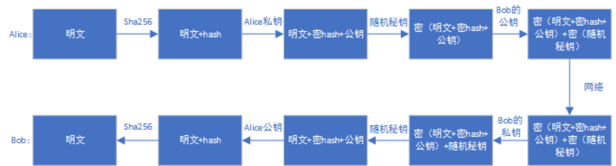
6.4.5 AVB
AVB is short for Android Verified Boot, a set of firmware verification process designed by Google, mainly used to verify the boot system and other firmware. rockchip Secure Boot achieve a complete set of Secure Boot verification program with reference to AVB and the verification method used in communication.
6.4.5.1 AVB Characteristics
safety check integrity check anti-rollback protection persistent partition support chained partitions support, can be consistent with boot, system signing private key, or oem can save private key by itself, but must be signed by PRK.
6.4.5.2 Key+signature+certificate
#!/bin/sh
touch temp.bin
openssl genpkey -algorithm RSA -pkeyopt rsa_keygen_bits:4096 -outform PEM -out
testkey_prk.pem
openssl genpkey -algorithm RSA -pkeyopt rsa_keygen_bits:4096 -outform PEM -out
testkey_psk.pem
openssl genpkey -algorithm RSA -pkeyopt rsa_keygen_bits:4096 -outform PEM -out
testkey_pik.pem
python avbtool make_atx_certificate --output=pik_certificate.bin --subject=temp.bin --
subject_key=testkey_pik.pem --subject_is_intermediate_authority --subject_key_version 42 --
authority_key=testkey_prk.pem
python avbtool make_atx_certificate --output=psk_certificate.bin --subject=product_id.bin --
subject_key=testkey_psk.pem --subject_key_version 42 --authority_key=testkey_pik.pem
python avbtool make_atx_metadata --output=metadata.bin --
intermediate_key_certificate=pik_certificate.bin --
product_key_certificate=psk_certificate.bin
permanent_attributes.bin gernerate:
python avbtool make_atx_permanent_attributes --output=permanent_attributes.bin --
product_id=product_id.bin --root_authority_key=testkey_prk.pem
Among them, product_id.bin needs to be defined by yourself, which occupies 16 bytes and can be used as the product ID definition. boot.img signature example:
avbtool add_hash_footer --image boot.img --partition_size 33554432 --partition_name boot --
key testkey_psk.pem --algorithm SHA256_RSA4096
Note: The partition size should be at least 64K larger than the original firmware, the size should be 4K aligned, and not larger than the partition size defined in parameter.txt. sytem.img signature example:
avbtool add_hashtree_footer --partition_size 536870912 --partition_name system --image
system.img --algorithm SHA256_RSA4096 --key testkey_psk.pem
Generate vbmeta which includes metadata.bin, command example is as follows:
python avbtool make_vbmeta_image --public_key_metadata metadata.bin --
include_descriptors_from_image boot.img --include_descriptors_from_image system.img --
generate_dm_verity_cmdline_from_hashtree system.img --algorithm SHA256_RSA4096 --key
testkey_psk.pem --output vbmeta.img
The resulting vbmeta.img is eventually written to the corresponding partition, e.g. the vbmeta partition. Generate PrivateKey.pem and PublicKey.pem with SecureBootTool.
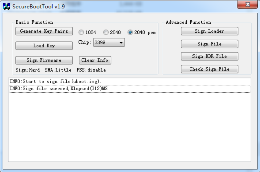
Sign permanent_attributes.bin:
openssl dgst -sha256 -out permanent_attributes_cer.bin -sign PrivateKey.pem
permanent_attributes.bin
permanent_attributes.bin is the secure authentication data for the whole system, it needs to write its hash to efuse or OTP, or its data is securely authenticated by the previous level (pre-load). Since there is insufficient efuse made by rockchip platform, the authentication of permanent_attributes.bin is authenticated by the public key of the preload plus the certificate of permanent_attributes.bin. For platforms with OTP with enough secure data space, the hash of permanent_attributes.bin will be written directly to the OTP. efuse and OTP support by platform:Please refer to the Driver Module section.
efuse platform pub_key download:
fastboot stage permanent_attributes.bin
fastboot oem fuse at-perm-attr
fastboot stage permanent_attributes_cer.bin
fastboot oem fuse at-rsa-perm-attr
OTP platform pub_key download:
fastboot stage permanent_attributes.bin
fastboot oem fuse at-perm-attr
The entire signature process:
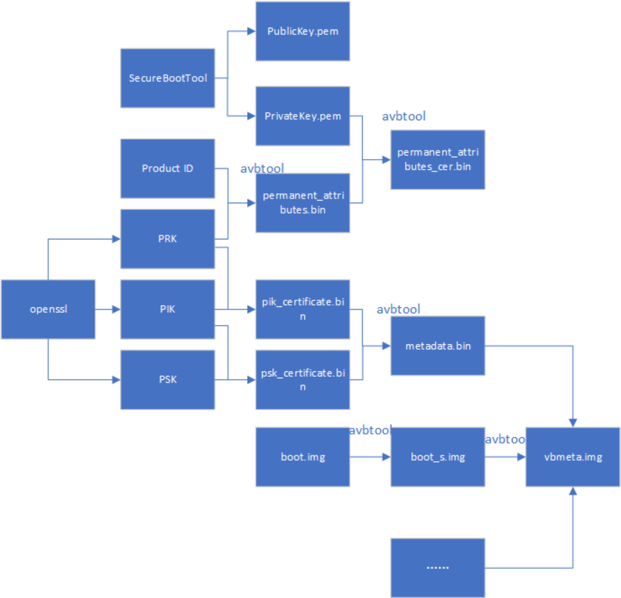
6.4.5.3 AVB Lock
fastboot oem at-lock-vboot
How to enter fastboot? please see the fastboot command support section.
6.4.5.4 AVB Unlock
Currently Rockchip uses strict security checksums, which need to be added to the corresponding defconfig.
CONFIG_RK_AVB_LIBAVB_ENABLE_ATH_UNLOCK=y
Otherwise you can just enter fastboot oem at-unlock-vboot to unlock the device, and boot vbmeta.img verification, and the device will be booted successfully even boot.img fails. First, a PUK needs to be generated:
openssl genpkey -algorithm RSA -pkeyopt rsa_keygen_bits:4096 -outform PEM -out
testkey_puk.pem
unlock_credential.bin is the certificate that needs to be downloaded to the device to be unlocked, and its generation process is as follows:
python avbtool make_atx_certificate --output=puk_certificate.bin --subject=product_id.bin --
subject_key=testkey_puk.pem --usage=com.google.android.things.vboot.unlock --
subject_key_version 42 --authority_key=testkey_pik.pem
Get unlock_credential.bin from the device, use the avb-challenge-verify.py script to get unlock_credential.bin, execute the following command to get unlock_credential.bin:
python avbtool make_atx_unlock_credential --output=unlock_credential.bin --
intermediate_key_certificate=pik_certificate.bin --
unlock_key_certificate=puk_certificate.bin --challenge=unlock_challenge.bin --
unlock_key=testkey_puk.pem
Eventually you can download the certificate to the device and unlock the device with the fastboot command as follows:
fastboot stage unlock_credential.bin
fastboot oem at-unlock-vboot
Final OTP device unlocking process:
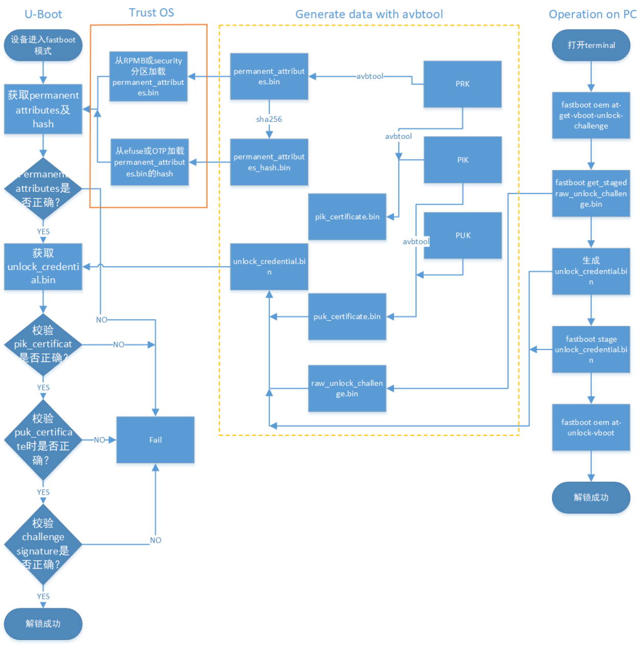
Final efuse device unlocking process:
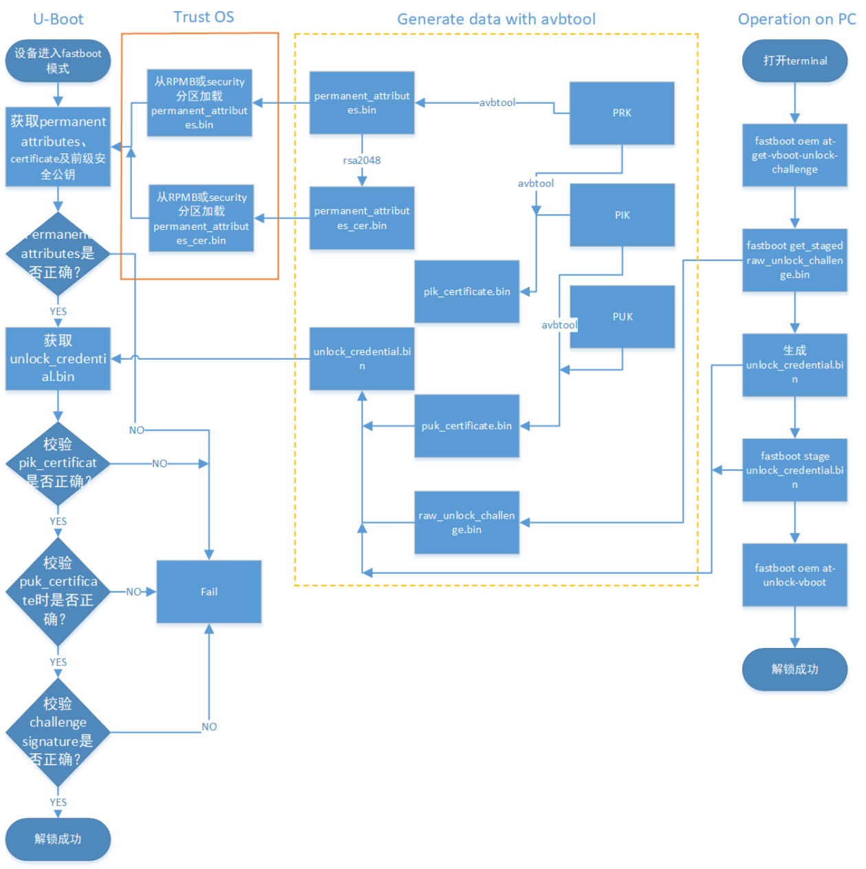
The final operating procedure is as follows:
- The device enters fastboot mode, and on the computer side, enter
fastboot oem at-get-vboot-unlock-challenge
fastboot get_staged raw_unlock_challenge.bin
Get the data with version, Product Id and 16 bytes random number, take out the random number as unlock_challenge.bin.
-
Use avbtool to generate unlock_credential.bin, refer to make_unlock.sh.
-
Input the following from PC
fastboot stage unlock_credential.bin
fastboot oem at-unlock-vboot
Note: At this point, the device is always in fastboot mode for the first time, and cannot be powered off, shut down, or rebooted during this period. Because after step 1, the device stores the generated random number, if you power off or reboot, the random number will be lost, and the subsequent verification of challenge signature will fail because of the random number mismatch. If enable:
CONFIG_MISC=y
CONFIG_ROCKCHIP_EFUSE=y
CONFIG_ROCKCHIP_OTP=y
It will use the CPUID as the challenge number, and the CPUID is matched with the machine, so the data will not be lost because of the shutdown, and the generated unlock_credential.bin can be reused. It saves the steps of generating unlock_challenge.bin and making unlock_credential.bin repeatedly. The steps to unlock again are changed to:
fastboot oem at-get-vboot-unlock-challenge
fastboot stage unlock_credential.bin
fastboot oem at-unlock-vboot
- The device enters the unlocked state and begins to unlock. make_unlock.sh refer to
#!/bin/sh
python avb-challenge-verify.py raw_unlock_challenge.bin product_id.bin
python avbtool make_unlock_credential --output=unlock_credential.bin --
intermediate_key_certificate=pik_certificate.bin --
unlock_key_certificate=puk_certificate.bin --challenge=unlock_challenge.bin --
unlock_key=testkey_puk.pem
avb-challenge-verify.py source code
#/user/bin/env python
"This is a test module for getting unlock_challenge.bin"
import sys
import os
from hashlib import sha256
def challenge_verify():
if (len(sys.argv) != 3) :
print "Usage: rkpublickey.py [challenge_file] [product_id_file]"
return
if ((sys.argv[1] == "-h") or (sys.argv[1] == "--h")):
print "Usage: rkpublickey.py [challenge_file] [product_id_file]"
return
try:
challenge_file = open(sys.argv[1], 'rb')
product_id_file = open(sys.argv[2], 'rb')
challenge_random_file = open('unlock_challenge.bin', 'wb')
challenge_data = challenge_file.read(52)
product_id_data = product_id_file.read(16)
product_id_hash = sha256(product_id_data).digest()
print("The challege version is %d" %ord(challenge_data[0]))
if (product_id_hash != challenge_data[4:36]) :
print("Product id verify error!")
return
challenge_random_file.write(challenge_data[36:52])
print("Success!")
finally:
if challenge_file:
challenge_file.close()
if product_id_file:
product_id_file.close()
if challenge_random_file:
challenge_random_file.close()
if __name__ == '__main__':
challenge_verify()
4.5.5 Enable U-boot Enabling avb requires trust support, which needs to be configured by U-Boot in the defconfig file:
CONFIG_OPTEE_CLIENT=y
CONFIG_OPTEE_V1=y
CONFIG_OPTEE_ALWAYS_USE_SECURITY_PARTITION=y // Security data is stored in the security
partition
CONFIG_OPTEE_V1: suitable for platforms with 312x,322x,3288,3228H,3368,3399. CONFIG_OPTEE_V2: suitable for platforms with 3326,3308. CONFIG_OPTEE_ALWAYS_USE_SECURITY_PARTITION: This macro is turned on when rpmb for emmc is not available; it is not turned on by default. The enablement of avb needs to be configured in the defconfig file:
CONFIG_AVB_LIBAVB=y
CONFIG_AVB_LIBAVB_AB=y
CONFIG_AVB_LIBAVB_ATX=y
CONFIG_AVB_LIBAVB_USER=y
CONFIG_RK_AVB_LIBAVB_USER=y
// The above options are mandatory, the following options support AVB and A/B features, the
two features can be used separately.
CONFIG_ANDROID_AB=y //This supports A/B
CONFIG_ANDROID_AVB=y //This supports A/B
// The following macros are for efuse-only platforms
CONFIG_ROCKCHIP_PRELOADER_PUB_KEY=y
// The following macros need to be turned on for strict unlock checksums
CONFIG_RK_AVB_LIBAVB_ENABLE_ATH_UNLOCK=y
// Enable security check
CONFIG_AVB_VBMETA_PUBLIC_KEY_VALIDATE=y
// If you need the cpuid as a challenge number, enable the following macro
CONFIG_MISC=y
CONFIG_ROCKCHIP_EFUSE=y
CONFIG_ROCKCHIP_OTP=y
6.4.5.5 Kernel Configuration
The checksums for system, vendor, oem, etc. are loaded by the kernel’s dm-verify module, so you need to enable this module. To enable AVB, you need to configure the parameter avb on the kernel dts as follows:
&firmware_android {
compatible = "android,firmware";
boot_devices = "fe330000.sdhci";
vbmeta {
compatible = "android,vbmeta";
parts = "vbmeta,boot,system,vendor,dtbo";
};
fstab {
compatible = "android,fstab";
vendor {
compatible = "android,vendor";
dev = "/dev/block/by-name/vendor";
type = "ext4";
mnt_flags = "ro,barrier=1,inode_readahead_blks=8";
fsmgr_flags = "wait,avb";
};
};
};
To enable the A/B system, you need to configure the slotselect parameter as follows:
firmware {
android {
compatible = "android,firmware";
fstab {
compatible = "android,fstab";
system {
compatible = "android,system";
dev = "/dev/block/by-name/system";
type = "ext4";
mnt_flags = "ro,barrier=1,inode_readahead_blks=8";
fsmgr_flags = "wait,verify,slotselect";
};
vendor {
compatible = "android,vendor";
dev = "/dev/block/by-name/vendor";
type = "ext4";
mnt_flags = "ro,barrier=1,inode_readahead_blks=8";
fsmgr_flags = "wait,verify,slotselect";
};
};
};
};
6.4.5.6 Android SDK
The following describes some of the configuration instructions on the Android SDK. AVB Enable Enable BOARD_AVB_ENABLE A/B system There are three main categories of these variables: Variables that must be defined by the A/B system AB_OTA_UPDATER := true AB_OTA_PARTITIONS := boot system vendor BOARD_BUILD_SYSTEM_ROOT_IMAGE := true TARGET_NO_RECOVERY := true BOARD_USES_RECOVERY_AS_BOOT := true PRODUCT_PACKAGES += update_engine update_verifier Variables that is optionally defined for A/B system PRODUCT_PACKAGES_DEBUG += update_engine_client Variables that cannot be defined in the A/B system BOARD_RECOVERYIMAGE_PARTITION_SIZE BOARD_CACHEIMAGE_PARTITION_SIZE BOARD_CACHEIMAGE_FILE_SYSTEM_TYPE
6.4.5.7 Cmdline New Content
Kernel command line: androidboot.verifiedbootstate=green androidboot.slot_suffix=_a dm="1
vroot none ro 1,0 1031864 verity 1 PARTUUID=b2110000-0000-455a-8000-44780000706f
PARTUUID=b2110000-0000-455a-8000-44780000706f 4096 4096 128983 128983 sha1
90d1d406caac04b7e3fbf48b9a4dcd6992cc628e 4172683f0d6b6085c09f6ce165cf152fe3523c89 10
restart_on_corruption ignore_zero_blocks use_fec_from_device PARTUUID=b2110000-0000-455a-
8000-44780000706f fec_roots 2 fec_blocks 130000 fec_start 130000" root=/dev/dm-0
androidboot.vbmeta.device=PARTUUID=f24f0000-0000-4e1b-8000-791700006a98
androidboot.vbmeta.avb_version=1.1 androidboot.vbmeta.device_state=unlocked
androidboot.vbmeta.hash_alg=sha512 androidboot.vbmeta.size=6528
androidboot.vbmeta.digest=41991c02c82ea1191545c645e2ac9cc7ca08b3da0a2e3115aff479d2df61feaccd
d35b6360cfa936f6f4381e4557ef18e381f4b236000e6ecc9ada401eda4cae
androidboot.vbmeta.invalidate_on_error=yes androidboot.veritymode=enforcing
Notes on a few parameters:
-
Why pass the PARTUUID of the vbmeta? To ensure the legitimacy of the subsequent use of the vbmeta hash-tree, the kernel needs to verify the vbmeta again, with digest as androidboot.vbmeta.digest.
-
skip_initramfs: boot ramdisk is packed to boot.img or not, in A/B system, ramdisk is not packed to boot.img, cmdline need to pass this parameter.
-
root=/dev/dm-0 enables dm-verify, specifies system.
-
androidboot.vbmeta.device_state: the state of android verify.
-
androidboot.verifiedbootstate: verification results. green: If in LOCKED state and an the key used for verification was not set by the end user. yellow: If in LOCKED state and an the key used for verification was set by the end user. orange: If in the UNLOCKED state. Special remarks on the dm=“1 vroot none ro……” parameter is generated:
avbtool make_vbmeta_image --include_descriptors_from_image boot.img --
include_descriptors_from_image system.img --generate_dm_verity_cmdline_from_hashtree
system.img --include_descriptors_from_image vendor.img --algorithm SHA512_RSA4096 --key
testkey_psk.pem --public_key_metadata metadata.bin --output vbmeta.img
When avbtool generates vbmeta, add –generate_dm_verity_cmdline_from_hashtree to the system firmware. dm=“1 vroot none ro……” will be saved to vbmeta. This part is Android-specific, if the partition only checksums to boot.img, you don’t need to add this parameter. Enabling BOARD_AVB_ENABLE in the Android SDK will add this information to the vbmeta.
6.4.6 Partition Reference
Newly added vbmeta partition and security partition, vbmeta partition stores firmware verification information, security partition stores encrypted security data.
FIRMWARE_VER:8.0
MACHINE_MODEL:RK3326
MACHINE_ID:007
MANUFACTURER: RK3326
MAGIC: 0x5041524B
ATAG: 0x00200800
MACHINE: 3326
CHECK_MASK: 0x80
PWR_HLD: 0,0,A,0,1
TYPE: GPT
CMDLINE:mtdparts=rk29xxnand:0x00002000@0x00004000(uboot),0x00002000@0x00006000(trust),0x0000
2000@0x00008000(misc),0x00008000@0x0000a000(resource),0x00010000@0x00012000(kernel),0x000020
00@0x00022000(dtb),0x00002000@0x00024000(dtbo),0x00000800@0x00026000(vbmeta),0x00010000@0x00
026800(boot),0x00020000@0x00036800(recovery),0x00038000@0x00056800(backup),0x00002000@0x0008
e800(security),0x000c0000@0x00090800(cache),0x00514000@0x00150800(system),0x00008000@0x00664
800(metadata),0x000c0000@0x0066c800(vendor),0x00040000@0x0072c800(oem),0x00000400@0x0076c800
(frp),-@0x0076cc00(userdata:grow)
uuid:system=af01642c-9b84-11e8-9b2a-234eb5e198a0
A/B System Partition Definition Reference:
FIRMWARE_VER:8.1
MACHINE_MODEL:RK3326
MACHINE_ID:007
MANUFACTURER: RK3326
MAGIC: 0x5041524B
ATAG: 0x00200800
MACHINE: 3326
CHECK_MASK: 0x80
PWR_HLD: 0,0,A,0,1
TYPE: GPT
CMDLINE:
mtdparts=rk29xxnand:0x00002000@0x00004000(uboot_a),0x00002000@0x00006000(uboot_b),0x00002000
@0x00008000(trust_a),0x00002000@0x0000a000(trust_b),0x00001000@0x0000c000(misc),0x00001000@0
x0000d000(vbmeta_a),0x00001000@0x0000e000(vbmeta_b),0x00020000@0x0000e000(boot_a),0x00020000
@0x0002e000(boot_b),0x00100000@0x0004e000(system_a),0x00300000@0x0032e000(system_b),0x001000
00@0x0062e000(vendor_a),0x00100000@0x0072e000(vendor_b),0x00002000@0x0082e000(oem_a),0x00002
000@0x00830000(oem_b),0x0010000@0x00832000(factory),0x00008000@0x842000(factory_bootloader),
0x00080000@0x008ca000(oem),-@0x0094a000(userdata)
6.4.7 Fastboot Command
Under U-Boot, you can enter fastboot by entering the command:
fastboot usb 0
6.4.7.1 Quick Overview of Commands
fastboot flash < partition > [ < filename > ]
fastboot erase < partition >
fastboot getvar < variable > | all
fastboot set_active < slot >
fastboot reboot
fastboot reboot-bootloader
fastboot flashing unlock
fastboot flashing lock
fastboot stage [ < filename > ]
fastboot get_staged [ < filename > ]
fastboot oem fuse at-perm-attr-data
fastboot oem fuse at-perm-attr
fastboot oem fuse at-rsa-perm-attr
fastboot oem at-get-ca-request
fastboot oem at-set-ca-response
fastboot oem at-lock-vboot
fastboot oem at-unlock-vboot
fastboot oem at-disable-unlock-vboot
fastboot oem fuse at-bootloader-vboot-key
fastboot oem format
fastboot oem at-get-vboot-unlock-challenge
fastboot oem at-reset-rollback-index
6.4.7.2 Command Usage
- fastboot flash < partition > [ < filename > ] Function: Write Partition .
Example: fastboot flash boot boot.img
- fastboot erase < partition > Function: Erase the partition.
Example: fastboot erase boot
- fastboot getvar < variable > | all Function: Get device information Example: fastboot getvar all (get all information about the device) Parameters that can be brought with variable:
version /* fastboot version */
version-bootloader /* U-Boot version */
version-baseband
product /* Product Information */
serialno /* Serial number*/
secure /* Whether to enable security checking */
max-download-size /* maximum number of bytes supported by fastboot in a
single transfer */
logical-block-size /* Number of logical blocks */
erase-block-size /* Number of erased blocks*/
partition-type : < partition > /* Partition type */
partition-size : < partition > /* Partition size*/
unlocked /* Device lock status */
off-mode-charge
battery-voltage
variant
battery-soc-ok
slot-count /* Number of slots*/
has-slot: < partition > /* Check if the partition name is in the slot*/
current-slot /* Currently booted slots */
slot-suffixes /* The current slot of the device, print its name. */
slot-successful: < _a | _b > /* Check if the partition is properly verified and
booted*/
slot-unbootable: < _a | _b > /* Check if the partition is set to unbootable */
slot-retry-count: < _a | _b > /* Checkthe number of retry-counts for partition */
at-attest-dh
at-attest-uuid
at-vboot-state
fastboot getvar all example:
PS E:\U-Boot-AVB\adb> .\fastboot.exe getvar all
(bootloader) version:0.4
(bootloader) version-bootloader:U-Boot 2017.09-gc277677
(bootloader) version-baseband:N/A
(bootloader) product:rk3229
(bootloader) serialno:7b2239270042f8b8
(bootloader) secure:yes
(bootloader) max-download-size:0x04000000
(bootloader) logical-block-size:0x512
(bootloader) erase-block-size:0x80000
(bootloader) partition-type:bootloader_a:U-Boot
(bootloader) partition-type:bootloader_b:U-Boot
(bootloader) partition-type:tos_a:U-Boot
(bootloader) partition-type:tos_b:U-Boot
(bootloader) partition-type:boot_a:U-Boot
(bootloader) partition-type:boot_b:U-Boot
(bootloader) partition-type:system_a:ext4
(bootloader) partition-type:system_b:ext4
(bootloader) partition-type:vbmeta_a:U-Boot
(bootloader) partition-type:vbmeta_b:U-Boot
(bootloader) partition-type:misc:U-Boot
(bootloader) partition-type:vendor_a:ext4
(bootloader) partition-type:vendor_b:ext4
(bootloader) partition-type:oem_bootloader_a:U-Boot
(bootloader) partition-type:oem_bootloader_b:U-Boot
(bootloader) partition-type:factory:U-Boot
(bootloader) partition-type:factory_bootloader:U-Boot
(bootloader) partition-type:oem_a:ext4
(bootloader) partition-type:oem_b:ext4
(bootloader) partition-type:userdata:ext4
(bootloader) partition-size:bootloader_a:0x400000
(bootloader) partition-size:bootloader_b:0x400000
(bootloader) partition-size:tos_a:0x400000
(bootloader) partition-size:tos_b:0x400000
(bootloader) partition-size:boot_a:0x2000000
(bootloader) partition-size:boot_b:0x2000000
(bootloader) partition-size:system_a:0x20000000
(bootloader) partition-size:system_b:0x20000000
(bootloader) partition-size:vbmeta_a:0x10000
(bootloader) partition-size:vbmeta_b:0x10000
(bootloader) partition-size:misc:0x100000
(bootloader) partition-size:vendor_a:0x4000000
(bootloader) partition-size:vendor_b:0x4000000
(bootloader) partition-size:oem_bootloader_a:0x400000
(bootloader) partition-size:oem_bootloader_b:0x400000
(bootloader) partition-size:factory:0x2000000
(bootloader) partition-size:factory_bootloader:0x1000000
(bootloader) partition-size:oem_a:0x10000000
(bootloader) partition-size:oem_b:0x10000000
(bootloader) partition-size:userdata:0x7ad80000
(bootloader) unlocked:no
(bootloader) off-mode-charge:0
(bootloader) battery-voltage:0mv
(bootloader) variant:rk3229_evb
(bootloader) battery-soc-ok:no
(bootloader) slot-count:2
(bootloader) has-slot:bootloader:yes
(bootloader) has-slot:tos:yes
(bootloader) has-slot:boot:yes
(bootloader) has-slot:system:yes
(bootloader) has-slot:vbmeta:yes
(bootloader) has-slot:misc:no
(bootloader) has-slot:vendor:yes
(bootloader) has-slot:oem_bootloader:yes
(bootloader) has-slot:factory:no
(bootloader) has-slot:factory_bootloader:no
(bootloader) has-slot:oem:yes
(bootloader) has-slot:userdata:no
(bootloader) current-slot:a
(bootloader) slot-suffixes:a,b
(bootloader) slot-successful:a:yes
(bootloader) slot-successful:b:no
(bootloader) slot-unbootable:a:no
(bootloader) slot-unbootable:b:yes
(bootloader) slot-retry-count:a:0
(bootloader) slot-retry-count:b:0
(bootloader) at-attest-dh:1:P256
(bootloader) at-attest-uuid:
all: Done!
finished. total time: 0.636s
- fastboot set_active < slot > Function: Set the slot for reboot.
Example: fastboot set_active _a
-
fastboot reboot Function: Reboot the device for normal startup Example: fastboot reboot
-
fastboot reboot-bootloader Function: Reboot the device to enter fastboot mode.
Example: fastboot reboot-bootloader
-
fastboot flashing unlock Function: Unlock the device and allow firmware downloading Example: fastboot flashing unlock
-
fastboot flashing lock Function: Lock the device, prohibit dowloading Example: fastboot flashing lock
-
fastboot stage [ < filename > ] Function: Download data to device-side memory, the memory start address is CONFIG_FASTBOOT_BUF_ADDR.
Example: fastboot stage permanent_attributes.bin
-
fastboot get_staged [ < filename > ] Function: Getting data from the device side Example: fastboot get_staged raw_unlock_challenge.bin
-
fastboot oem fuse at-perm-attr Function: write permanent_attributes.bin and hash Example: fastboot stage permanent_attributes.bin fastboot oem fuse at-perm-attr
-
fastboot oem fuse at-perm-attr-data Function: Burn only permanent_attributes.bin to the secure storage area (RPMB) Example: fastboot stage permanent_attributes.bin fastboot oem fuse at-perm-attr-data
-
fastboot oem at-get-ca-request
-
fastboot oem at-set-ca-response
-
fastboot oem at-lock-vboot Function: Lock device Example: fastboot oem at-lock-vboot
-
fastboot oem at-unlock-vboot Function: Unlock the device, now support authenticated unlock Example: fastboot oem at-get-vboot-unlock-challenge fastboot get_staged raw_unlock_challenge.bin ./make_unlock.sh(refer to make_unlock.sh ) fastboot stage unlock_credential.bin fastboot oem at-unlock-vboot
-
fastboot oem fuse at-bootloader-vboot-key Function: download bootloader key hash Example: fastboot stage bootloader-pub-key.bin fastboot oem fuse at-bootloader-vboot-key
-
fastboot oem format Function: reformat partitions, partition information depends on $partitions Example: fastboot oem format
-
fastboot oem at-get-vboot-unlock-challenge Function: authenticated unlock, need to get unlock challenge data Example: please refer to 16. fastboot oem at-unlock-vboot
-
fastboot oem at-reset-rollback-index Function: Reset the rollback data of the device Example: fastboot oem at-reset-rollback-index
-
fastboot oem at-disable-unlock-vboot Function: Disables the fastboot oem at-unlock-vboot command.
Example: fastboot oem at-disable-unlock-vboot
6.4.8 Firmware Downloading
The following is the windows firmware downloading tool
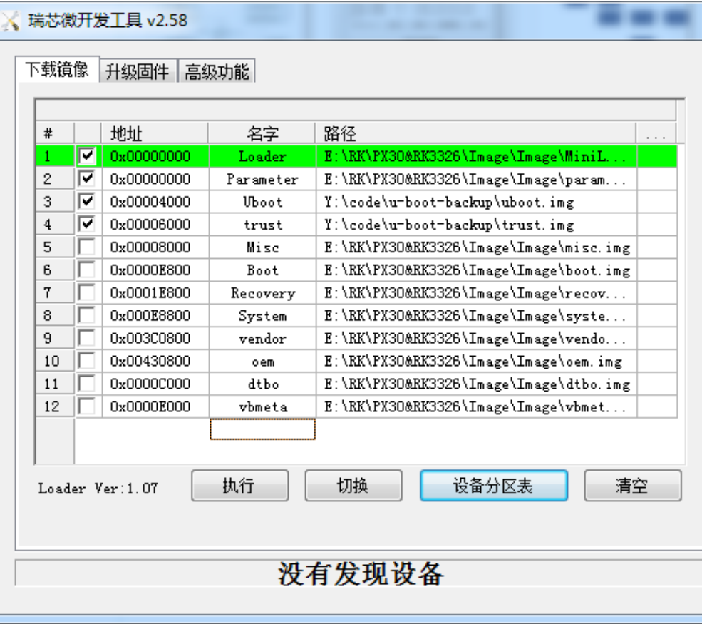
A/B System downloading
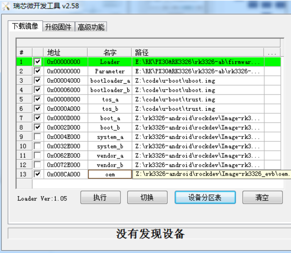
6.4.9 Pre-loader Verified
Please refer to《Rockchip-Secure-Boot-Application-Note.md》
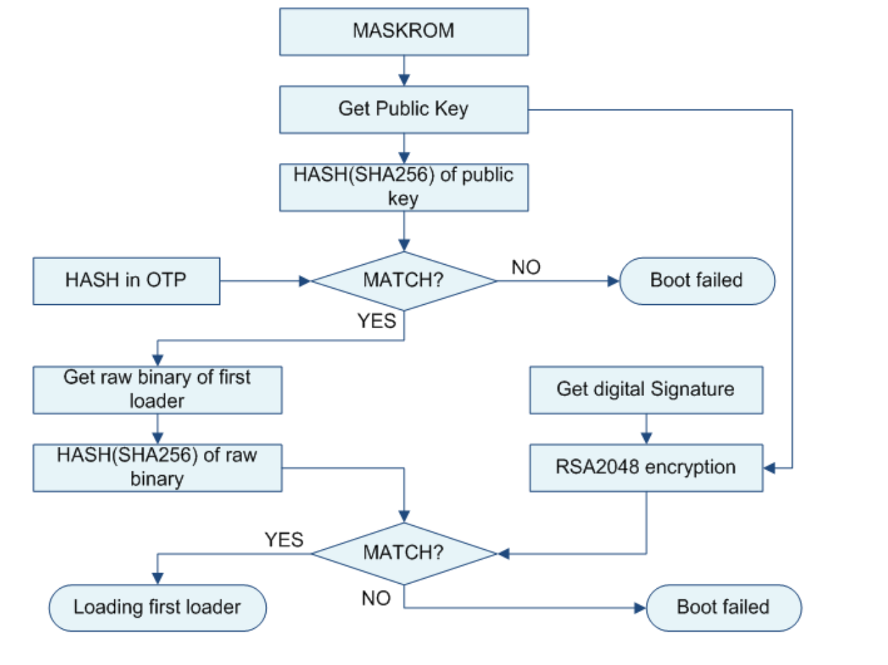
6.4.10 U-boot Verified
OTP Device Verification Process:
Efuse Device Verification Process:
6.4.11 System Verification Boot
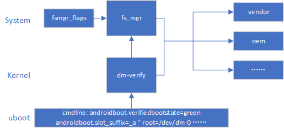
he system boots to the kernel, which first parses the cmdline parameters passed by U-Boot to verify whether the system boots with dm-verify, then loads and enables the system fs_mgr service. fs_mgr verifies that the firmware is loaded based on the fsmgr_flags parameter. The firmware hash & hash tree is stored in vbmeta.img with the following parameters avb: loads and verifies partition in avb mode slotselect: The slotselect is for A/B, and will be loaded with the parameter “androidboot.slot_suffix=_a” in the cmdline.
6.4.12 Linux AVB
The following describes the AVB operation and verification process based on linux environment.
6.4.12.1 Operating Workflow
-
Generate complete firmware
-
Generate PrivateKey.pem and PublicKey.pem using SecureBootConsole with rk_sign_tool with the following commands
rk_sign_tool cc --chip 3399
rk_sign_tool kk --out .
- load key
rk_sign_tool lk --key privateKey.pem --pubkey publicKey.pem
- Signature loader
rk_sign_tool sl --loader loader.bin
- Signature uboot.img & trust.img
rk_sign_tool si --img uboot.img
rk_sign_tool si --img trust.img
- avb signature firmware preparations: Prepare empty temp.bin, 16-byte product_id.bin, boot.img to be signed, and run the following code
#!/bin/bash
touch temp.bin
openssl genpkey -algorithm RSA -pkeyopt rsa_keygen_bits:4096 -outform PEM -out
testkey_prk.pem
openssl genpkey -algorithm RSA -pkeyopt rsa_keygen_bits:4096 -outform PEM -out
testkey_psk.pem
openssl genpkey -algorithm RSA -pkeyopt rsa_keygen_bits:4096 -outform PEM -out
testkey_pik.pem
python avbtool make_atx_certificate --output=pik_certificate.bin --subject=temp.bin --
subject_key=testkey_pik.pem --subject_is_intermediate_authority --subject_key_version 42 --
authority_key=testkey_prk.pem
python avbtool make_atx_certificate --output=psk_certificate.bin --subject=product_id.bin --
subject_key=testkey_psk.pem --subject_key_version 42 --authority_key=testkey_pik.pem
python avbtool make_atx_metadata --output=metadata.bin --
intermediate_key_certificate=pik_certificate.bin --
product_key_certificate=psk_certificate.bin
python avbtool make_atx_permanent_attributes --output=permanent_attributes.bin --
product_id=product_id.bin --root_authority_key=testkey_prk.pem
python avbtool add_hash_footer --image boot.img --partition_size 33554432 --partition_name
boot --key testkey_psk.pem --algorithm SHA256_RSA4096
python avbtool make_vbmeta_image --public_key_metadata metadata.bin --
include_descriptors_from_image boot.img --algorithm SHA256_RSA4096 --key testkey_psk.pem --
output vbmeta.img
openssl dgst -sha256 -out permanent_attributes_cer.bin -sign PrivateKey.pem
permanent_attributes.bin
generate vbmeta.img, permanent_attributes_cer.bin, permanent_attributes.bin. This step signs boot.img……
7.Firmware downloading
rkdeveloptool db loader.bin
rkdeveloptool ul loader.bin
rkdeveloptool gpt parameter.txt
rkdeveloptool wlx uboot uboot.img
rkdeveloptool wlx trust trust.img
rkdeveloptool wlx boot boot.img
rkdeveloptool wlx system system.img
For rkdeveloptool, please refer tohttps://github.com/rockchip-linux/rkdeveloptool>
- Download permanent_attributes_cer.bin, permanent_attributes.bin OTP platform available:
fastboot stage permanent_attributes.bin
fastboot oem fuse at-perm-attr
efuse platform available:
fastboot stage permanent_attributes.bin
fastboot oem fuse at-perm-attr
fastboot stage permanent_attributes_cer.bin
fastboot oem fuse at-rsa-perm-attr
- efuse downloading (efuse tool is only available in windows version at the moment), select a specific loader, select the corresponding device, and click start download.
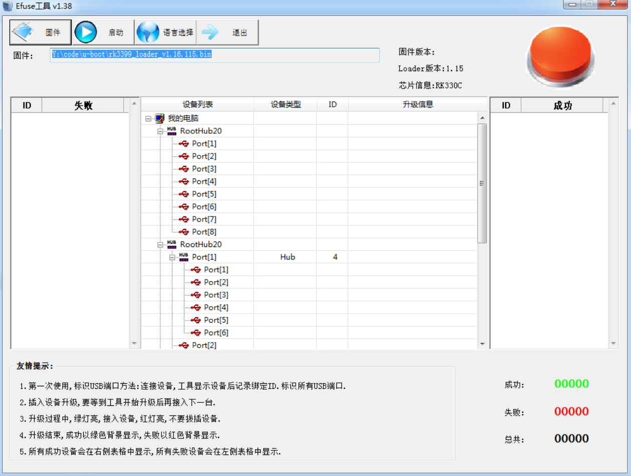
- OTP platform loader public key download Please refer to Rockchip-Secure-Boot-Application-Note.md
6.4.12.2 Verification Process
[TODO]
6.5 SD Boot and Upgrade
6.5.1 Brief Introduction
Rockchip now categorizes SD cards into regular SD cards, SD upgrade cards, SD boot cards, and SD repair cards. You can download the update.img to the SD card through the Rockchip by creating upgrade-disk tool to create different card types
| SD Card Category |
Function |
|---|---|
| Regular SD card |
Common storage devices |
| SD Upgrade Card |
The device boots from the SD card to recovery, which is responsible for updating the firmware in the sd to the device memory. |
| SD Boot Card | Device boots directly from SD card |
| SD Repair Card | Copy the firmware from the SD card to the device memory, starting with the pre- loader. |
6.5.2 SD Card Category
6.5.2.1 Regular SD Card
A regular SD card is used exactly the same as a PC, and can be used as normal storage space in U-Boot and Kernel systems without any tools to do anything with the SD card.
6.5.2.2 SD Upgrade Card
SD upgrade card is made by RK’s tool to realize firmware upgrade from SD card to local storage (e.g. eMMC, nand flash). SD card upgrade is a firmware upgrade method which can be detached from PC or network. Specifically, the SD card boot code is written to the reserved area of the SD card, and then the firmware is copied to the visible partition of the SD card, when the master control boots from the SD card, the SD card boot code and upgrade code will download the firmware to the local master storage. At the same time, the SD upgrade card supports PCBA testing and copying of demo files. These functions of the SD upgrade card can make the firmware upgrade independent of the PC and improve the production efficiency. If you only need to update the firmware and demo files on the SD card, you can follow the steps below to complete the process:
-
Copy the firmware to the root directory of the SD card and rename it sdupdate.img
-
Copy the demo file to the demo directory in the root directory of the SD card. SD bootable upgrade card format (not GPT)
| Offset | Data segment |
|---|---|
| disk sector 0 | MBR |
| disk sector 64-4M | IDBLOCK(Start flag set to 0) |
| 4M-8M | Parameter |
| 12M-16M | uboot |
| 16M-20M | trust |
| …… | misc |
| …… | resource |
| …… | kernel |
| …… | recovery |
| Room left | Fat32 stores update.img |
SD bootable upgrade card format (GPT)
| Offset | Data segment |
|---|---|
| disk sector 0 | MBR |
| disk sector 1-34 | GPT partition |
| disk sector 64-4M | IDBLOCK(Start flag set to 0) |
| 4M-8M | Parameter |
| …… | uboot |
| …… | trust |
| …… | misc |
| …… | resource |
| …… | kernel |
| …… | recovery |
| Room left | Fat32 stores update.img |
6.5.2.3 SD Boot Card
The SD boot card is made by RK’s tool to realize booting directly from the SD card, which greatly facilitates the user to update and boot new firmware without having to re- download the firmware into the device storage. The specific realization is to downlaod the firmware into the SD card and use the SD card as the main storage. When the master control starts from the SD card, the firmware and temporary files are stored on the SD card,
and it can work normally with or without the local master storage. Currently, it is mainly used for device system booting from SD card, or for PCBA testing.
Note: PCBA test is only a function under recovery, it can be used for SD upgrad card and SD boot card. SD boot card format (not GPT)
| Offset | Data segment |
|---|---|
| disk sector 0 | MBR |
| disk sector 64-4M | IDBLOCK(Start flag set to 0) |
| 4M-8M | Parameter |
| 8M-12M | uboot |
| 12M-16M | trust |
| …… | misc |
| …… | resource |
| …… | boot |
| …… | kernel |
| …… | recovery |
| …… | system |
| …… | user |
SD Boot Card Format (GPT)
| Offset | Data segment |
|---|---|
| disk sector 0 | MBR |
| disk sector 1-34 | GPT partition |
| disk sector 64-4M | IDBLOCK(Start flag set to 1) |
| …… | uboot |
| …… | Boot |
| …… | trust |
| …… | resource |
| …… | kernel |
| …… | recovery |
| …… | system |
| …… | vendor |
| …… | oem |
| …… | user |
| the last 33 disk sector | Backup GPT |
6.5.2.4 SD Repair Card
The SD Repair Card is similar to the function of SD upgrade card, but the firmware upgrade is done by the miniloader. First the tool writes the boot code to the reserved area of the SD card, then it copies the firmware to the visible partitions of the SD card, and when the master is booted from the SD card, the SD card upgrade code upgrades the firmware to the local master storage. It is mainly used when the firmware of the device is damaged and the SD card can repair the device. SD repair card format (not GPT)
| Offset | Data segment |
|---|---|
| disk sector 0 | MBR |
| disk sector 64-4M | IDBLOCK(Start flag set to 2) |
| 4M-8M | Parameter |
| 8M-12M | uboot |
| 12M-16M | trust |
| …… | misc |
| …… | resource |
| …… | boot |
| …… | kernel |
| …… | recovery |
| …… | system |
| …… | user |
SD Repaid Card Format(GPT)
| Offset | Data segment |
|---|---|
| disk sector 0 | MBR |
| disk sector 1-34 | GPT Partition |
| disk sector 64-4M | IDBLOCK(Start flag set to 2) |
| …… | uboot |
| …… | Boot |
| …… | trust |
| …… | resource |
| …… | kernel |
| …… | recovery |
| …… | system |
| …… | vendor |
| …… | oem |
| …… | user |
| Last 33 sectors | Backup GPT |
6.5.3 Firmware Logo
SD cards are used as a variety of different functions and will make some markings inside the sd card. At sector 64 of the SD card, if the start flag (magic number) is 0xFCDC8C3B, then it is a special card that will read the firmware from the SD card and boot the device. If not, it will be treated as a normal SD card. At sector (64 + 616bytes), the various card logos are stored. There are currently three types:
| Card logo | Card Category |
|---|---|
| 0 | SD upgrade card or PCBA test card |
| 1 | SD Boot Card |
| 2 | SD Repair Card |
6.5.4 Boot Process
The boot process of SD card can be divided into pre-loader boot process and uboot boot process. Both processes need to load and detect the SD card and the Startup Flag in the IDB Block of the SD card, and will perform different functions according to these flags. The process is as follows:
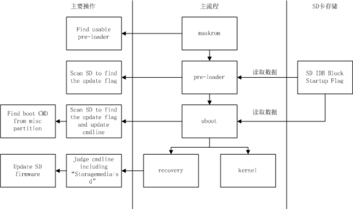
6.5.4.1 Pre-loader Boot
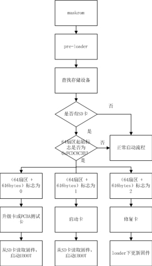
maskrom first finds a copy of the available miniloader firmware (you can determine the boot storage media supported by Maskrom from the TRM and prioritize them, maskrom scans the available storage for firmware), then jumps to the miniloader. miniloader re-finds the storage device, and if it detects an SD card, it detects if the SD card contains IDB format firmware. If SD card is detected, check if SD card contains IDB format firmware. If yes, then determine the card flag. If the SD card is available and the flag bit is ‘0’ or ‘1’, then read the U-Boot firmware from the SD card and load and boot the U-Boot, if the flag is ‘2’, then enter the process of repairing the card and update the firmware under the loader. The normal boot process is to scan for other storage and load and boot the next level loader.
6.5.4.2 U-Boot Boot
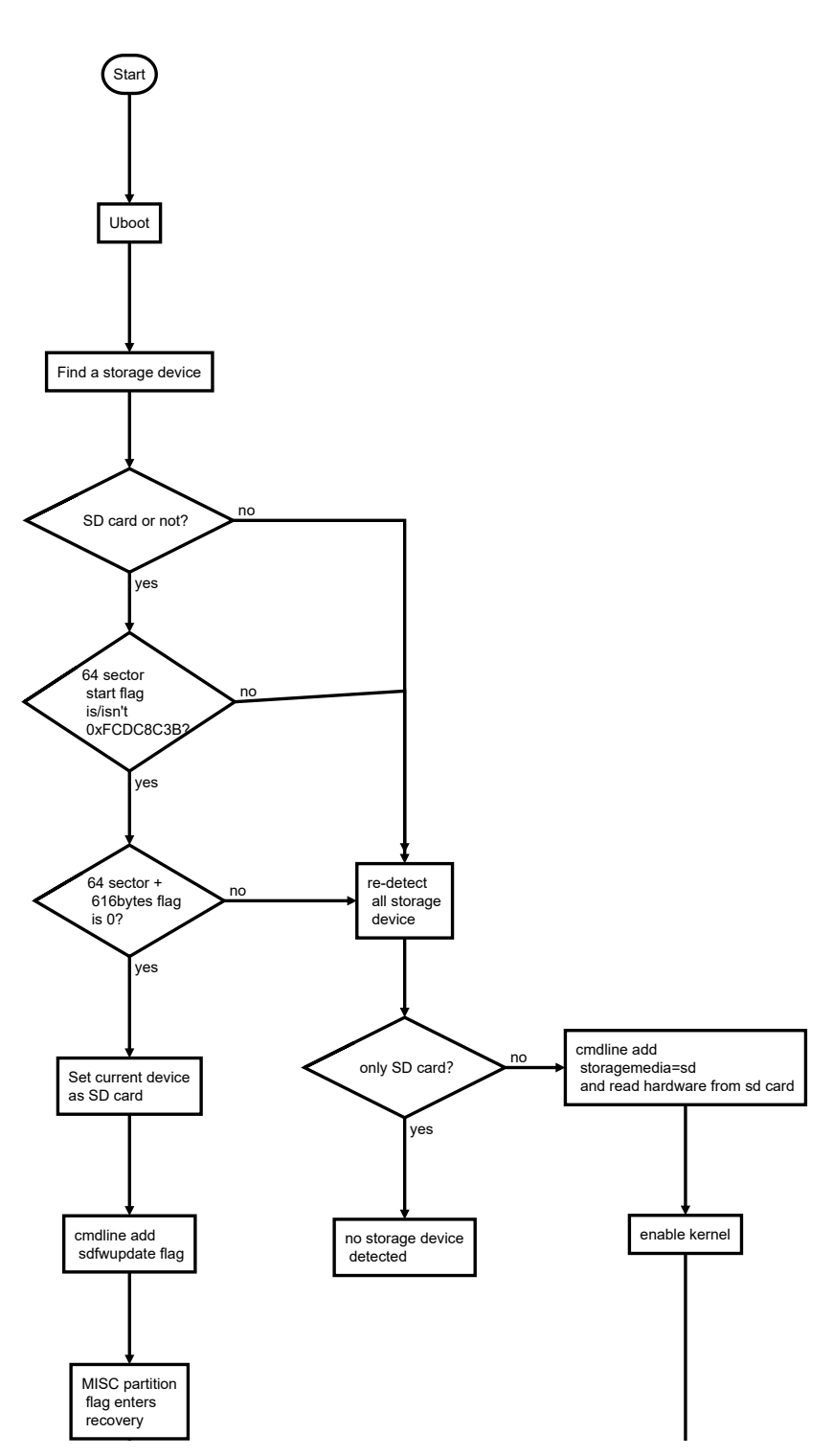
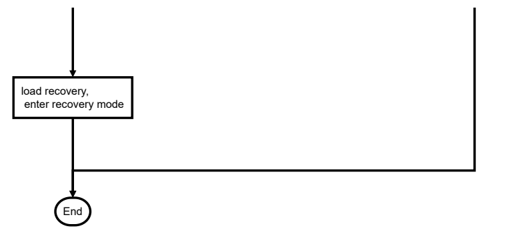
SD upgrade card: U-Boot re-search the storage device, if SD card is detected, check if SD card contains IDB format firmware. If yes, then determine if the card bias flag is 0, and add ‘sdfwupdate’ to the cmdline passed to the kernel. Finally, read the misc partition of the SD card, read the boot mode of the card, if it is recovery mode, load and start recovery. SD boot card: U-Boot re-search the storage device, if it detects SD card, it will check whether SD card contains IDB format firmware, if yes, then determine whether the card flag is 1. Finally, read the misc partition of the SD card and read the boot mode of the card, if it is recovery, load the boot recovery, if it is normal mode, load the boot kernel.
6.5.4.3 Recovery and PCBA
For details, please refer to Rockchip Recovery User Operation Guide V1.03.pdf
6.5.5 Notes
U-Boot needs to configure CONFIG_RKPARM_PARTITION when making non-GPT format firmware. When making SD upgrade card, update.img must contain MiniloaderAll.bin, parameter.txt, uboot.img, trust.img, misc.img, resource.img, recovery.img, or else the update.img will fail to write MBR.
7. Chapter-7 Configuration Trimming
TODO
8. Chapter-8 Debugging Tools
This section focuses on some of the common debugging tools used in the U-Boot stage, including the use of commands, scripts, configuration options, boot printing, and so on.
8.1 DEBUG
Function: Enables global debug() printing. This can be enabled by adding a macro definition to rkxxx_common.h for each platform:
#define DEBUG
8.2 Initcall
Function: Prints the boot process. U-Boot’s boot is essentially a series of initcall calls, changing debug() to printf() within the initcall_run_list() function.
Example:
U-Boot 2017.09-01725-g03b8d3b-dirty (Jul 06 2018 - 10:08:27 +0800)
initcall: 0000000000214388
initcall: 0000000000214724
Model: Rockchip RK3399 Evaluation Board
initcall: 0000000000214300
DRAM: initcall: 0000000000203f68
initcall: 0000000000214410 // Combine with disassembly to find the function corresponding
to the address
initcall: 00000000002140dc
....
3.8 GiB
initcall: 00000000002143b8
....
Relocation Offset is: f5c03000
initcall: 00000000f5e176bc
initcall: 00000000002146a4 (relocated to 00000000f5e176a4)
initcall: 0000000000214668 (relocated to 00000000f5e17668)
...
8.3 IO Command
Function: Reads and writes memory.
// read
md - memory display
Usage: md [.b, .w, .l, .q] address [# of objects]
// write
mw - memory write (fill)
Usage: mw [.b, .w, .l, .q] address value [count]
Read operation.
Example: Displays 0x10 consecutive data starting at address 0x76000000.
=> md.l 0x76000000 0x10
76000000: fffffffe ffffffff ffffffff ffffffff ................
76000010: ffffffdf ffffffff feffffff ffffffff ................
76000020: ffffffff ffffffff ffffffff ffffffff ................
76000030: ffffffff ffffffff ffffffff ffffffff ................
Write operation.
Example: Assign 0x1234 to address 0x76000000;
=> mw.l 0x76000000 0xffff1234 // Higher 16 bits have mask
=> md.l 0x76000000 0x10 // readback
76000000: ffff1234 ffffffff ffffffff ffffffff ................
76000010: ffffffdf ffffffff feffffff ffffffff ................
76000020: ffffffff ffffffff ffffffff ffffffff ................
76000030: ffffffff ffffffff ffffffff ffffffff ................
8.4 IOMEM Command
Function: Read memory. More flexible than the md command, obtains base address information by automatically parsing DTS nodes.
=> iomem
iomem - Show iomem data by device compatible
Usage:
// @<compatible>: Keyword matching for the compatible part of the node
iomem <compatible> <start offset> <end offset>
eg: iomem -grf 0x0 0x200
Example: RK3228 reads the data from 0x00 to 0x20 in GRF:
// The keyword “-grf” is used here to distinguish it from “rockchip, rk3288-pmugrf”.
=> iomem -grf 0x0 0x20
rockchip,rk3228-grf:
11000000: 00000000 00000000 00004000 00002000
11000010: 00000000 00005028 0000a5a5 0000aaaa
11000020: 00009955
8.5 I2C Command
Function: read/write i2c device .
=> i2c
i2c - I2C sub-system
Usage:
i2c dev [dev] - show or set current I2C bus
i2c md chip address[.0, .1, .2] [# of objects] - read from I2C device
i2c mw chip address[.0, .1, .2] value [count] ‐ write to I2C device (fill)
......
Read operation.
Example:
=> i2c dev 0 // Switch to i2c0 (just specify once)
Setting bus to 0
=> i2c md 0x1b 0x2e 0x20 // The i2c device address is 1b (7-bit address) and reads
0x20 consecutive register values starting at 0x2e
002e: 11 0f 00 00 11 0f 00 00 01 00 00 00 09 00 00 0c ................
003e: 00 0a 0a 0c 0c 0c 00 07 07 0a 00 0c 0c 00 00 00 ................
Write operation.
Example:
=> i2c dev 0 // Switch to i2c0 (just specify once)
Setting bus to 0
=> i2c mw 0x1b 0x2e 0x10 // The i2c device address is 1b (7-bit address), and the
0x2e register is assigned the value 0x10
=> i2c md 0x1b 0x2e 0x20 // readback
002e: 10 0f 00 00 11 0f 00 00 01 00 00 00 09 00 00 0c ................
003e: 00 0a 0a 0c 0c 0c 00 07 07 0a 00 0c 0c 00 00 00 ................
8.6 GPIO Command
Function: read/write pin input/output
=> gpio
gpio - query and control gpio pins
Usage:
gpio <input|set|clear|toggle> <pin>
- input/set/clear/toggle the specified pin
gpio status [-a] [<bank> | <pin>] - show [all/claimed] GPIOs
Check pin status: e.g. RV1126
=> gpio status -a
Bank A:
A0: input: 0 [ ]
A1: output: 1 [ ]
A2: input: 1 [ ]
...
A29: unused: 1 [ ]
A30: unknown
A31: unused: 0 [ ]
...
D6: input: 0 [ ]
D7: output: 1 [x] vcc18-lcd-n.gpio
...
D31: input: 0 [ ]
Bank E:
E0: input: 0 [ ]
E1: input: 0 [ ]
pin input:
=> gpio input A7
pin output INACTIVE:
=> gpio clear A7
pin output ACTIVE:
=> gpio set A7
Pin state switching: e.g. A7: input: 0 to A7: output: 1
=> gpio toggle A7
8.7 FDT Command
Function: Prints the contents of the DTB.
=> fdt
fdt - flattened device tree utility commands
Usage:
fdt addr [-c] <addr> [<length>] - Set the [control] fdt location to <addr>
fdt print <path> [<prop>] - Recursive print starting at <path>
fdt list <path> [<prop>] - Print one level starting at <path>
......
NOTE: Dereference aliases by omitting the leading '/', e.g. fdt print ethernet0.
The following two commands together can dump the device-tree completely:
=> fdt addr $fdt_addr_r // Specify fdt address
=> fdt print // Print out the entire contents of the fdt
8.8 MMC Command
Function: MMC device read/write, switching. MMC Device View:
=> mmc info
Device: dwmmc@ff0f0000 // device node
Manufacturer ID: 15
OEM: 100
Name: 8GME4
Timing Interface: High Speed // Speed Mode
Tran Speed: 52000000 // current speed
Rd Block Len: 512
MMC version 5.1
High Capacity: Yes
Capacity: 7.3 GiB // storage capacity
Bus Width: 8-bit // Bus width
Erase Group Size: 512 KiB
HC WP Group Size: 8 MiB
User Capacity: 7.3 GiB WRREL
Boot Capacity: 4 MiB ENH
RPMB Capacity: 512 KiB ENH
MMC device switching:
=> mmc dev 0 // Switch to eMMC
=> mmc dev 1 // Switch to sd card
MMC device reads and writes:
mmc read addr blk# cnt
mmc write addr blk# cnt
mmc erase blk# cnt
Example:
=> mmc read 0x70000000 0 1 // Read the first block of the MMC device, data size - 1
sector, into memory 0x70000000
=> mmc write 0x70000000 0 1 // Write 1 sector of data from memory 0x70000000 to the first
block of memory
=> mmc erase 0 1 // Erase 1 sector of data from the first block of memory.
If the MMC device reads or writes abnormally, you can quickly locate it by following these simple steps: Change debug() to printf() in drivers/mmc/dw_mmc.c and recompile and download. View the print information of the MMC device: If the last print is Sending CMD0, please check the hardware power supply, pin connection; check whether the software IOMUX is cut away by other IP; If the last print is Sending CMD8, in the Security Software section, configure the MMC device to allow access to secure storage; If all the initialization commands have passed and the last printout is Sending CMD18, please check the MMC hardware power supply, or check whether the capacitance of the power supply close to the MMC side is sufficient (can replace to a larger capacitor), check the software (can reduce the clock frequency), or try to switch the speed mode of the MMC device.
8.9 TimeStamp
Function: Adds a timestamp (relative time) to the U-Boot print message.
CONFIG_BOOTSTAGE_PRINTF_TIMESTAMP
Example:
[ 0.259266] U-Boot 2017.09-01739-g856f373-dirty (Jul 10 2018 - 20:26:05 +0800)
[ 0.260596] Model: Rockchip RK3399 Evaluation Board
[ 0.261332] DRAM: 3.8 GiB
Relocation Offset is: f5bfd000
Using default environment
[ 0.354038] dwmmc@fe320000: 1, sdhci@fe330000: 0
[ 0.521125] Card did not respond to voltage select!
[ 0.521188] mmc_init: -95, time 9
[ 0.671451] switch to partitions #0, OK
[ 0.671500] mmc0(part 0) is current device
[ 0.675507] boot mode: None
[ 0.683738] DTB: rk-kernel.dtb
[ 0.706940] Using kernel dtb
......
The timestamp only prints out the time of the current system timer, not do the timing from 0. So the timestamp prints only the relative time, not the absolute time.
8.10 DM Tree
Function: View the binding and probe status between all device-drivers.
=> dm tree
Class Probed Driver Name
----------------------------------------------------------
root [ + ] root_driver root_driver
syscon [ ] rk322x_syscon |-- syscon@11000000
serial [ + ] ns16550_serial |-- serial@11030000 *
clk [ + ] clk_rk322x |-- clock-controller@110e0000
sysreset [ ] rockchip_sysreset | |-- sysreset
reset [ ] rockchip_reset | `-- reset
mmc [ + ] rockchip_rk3288_dw_mshc |-- dwmmc@30020000 *
blk [ + ] mmc_blk | `-- dwmmc@30020000.blk *
ram [ ] rockchip_rk322x_dmc |-- dmc@11200000
serial [ + ] ns16550_serial |-- serial@11020000
i2c [ + ] i2c_rockchip |-- i2c@11050000
......
Print Meaning: List all the device-drivers that have completed the bind. List the affiliations between all uclass-device-driver [ + ] means the current driver has completed probe * Indicates that the current device-driver comes from the U-Boot DTB, otherwise it comes from the kernel DTB.
8.11 DM Uclass
Function: View all devices under a certain class uclass.
=> dm uclass
uclass 0: root
- * root_driver @ 7be54c88, seq 0, (req -1)
uclass 11: adc
- * saradc@ff100000 @ 7be56220, seq 0, (req -1)
......
uclass 40: backlight
- * backlight @ 7be81178, seq 0, (req -1)
uclass 77: key
- rockchip-key @ 7be811f0
......
8.12 Stacktrace.sh
Analyze the site of abort, dump_stack() using the call stack back mechanism. Please refer to the RK Architecture section.
8.13 System Crash
Function: Print the current CPU scene and call stack, suitable for use when the system is stuck. The serial port will dump similar information as abort every 5s.
CONFIG_ROCKCHIP_DEBUGGER
Get the call stack information and then use the stacktrace script to convert it. Please refer to the RK Architecture section.
8.14 CRC Check
Function: Checks the integrity of the firmware in RK format. The image header of the RK format contains the CRC32 of the entire image, which can be used to verify the integrity of the firmware by opening the following macro
CONFIG_ROCKCHIP_CRC
Example:
=Booting Rockchip format image=
kernel image CRC32 verify... okay. // kernel verifies success (or prints “fail!” if it
fails)
boot image CRC32 verify... okay. // boot verifies success (prints “fail!” if it
fails)
kernel @ 0x02080000 (0x01249808)
ramdisk @ 0x0a200000 (0x001e6650)
## Chapter-8 Flattened Device Tree blob at 01f00000
Booting using the fdt blob at 0x1f00000
'reserved-memory' secure-memory@20000000: addr=20000000 size=10000000
Loading Ramdisk to 08019000, end 081ff650 ... OK
Loading Device Tree to 0000000008003000, end 0000000008018c97 ... OK
Adding bank: start=0x00200000, size=0x08200000
Adding bank: start=0x0a200000, size=0xede00000
Starting kernel ...
8.15 HASH Check
Function: Check the integrity of the firmware in Android format.
ANDROID_BOOT_IMAGE_HASH
When this configuration is enabled, the integrity of the firmware is verified when loading firmware in Android format. For some historical reasons, if the above configuration does not verify the firmware correctly, please try turning on the following configuration at the same time:
HASH_ROCKCHIP_LEGACY
8.16 Modify DDR Capacity
The DDR initialization code during boot passes the DDR capacity to U-Boot, which will remove some safe memory before passing it to the kernel. The user can modify the DDR capacity to be passed to the kernel during the U-Boot stage. Example of Passing:
......
// The block of available memory passed to the kernel (with the safe memory block removed).
Adding bank: 0x00200000 - 0x08400000 (size: 0x08200000)
Adding bank: 0x0a200000 - 0x40000000 (size: 0x35e00000)
Total: 895.411 ms
Starting kernel ...
[ 0.000000] Booting Linux on physical CPU 0x0
Code Location:
./arch/arm/mach-rockchip/param.c
Modify the location:
struct memblock *param_parse_ddr_mem(int *out_count)
{
......
// Here is the capacity information that ddr passes to U-Boot.
// Because of the possibility of discontinuous addresses, they are passed in blocks,
specifying the starting address and size of each memory block separately.
// PS: It's usually contiguous memory and won't need to be chunked.
for (i = 0, n = 0; i < count; i++, n++) {
// For example, for a 2GB capacity (contiguous addresses): count = 1, base = 0, size
= 0x80000000.
// when debugging, users can modify here as needed.
base = t->u.ddr_mem.bank[i];
size = t->u.ddr_mem.bank[i + count];
/* 0~4GB */
if (base < SZ_4GB) {
mem[n].base = base;
mem[n].size = ddr_mem_get_usable_size(base, size);
if (base + size > SZ_4GB) {
n++;
mem[n].base_u64 = SZ_4GB;
mem[n].size_u64 = base + size - SZ_4GB;
}
} else {
/* 4GB+ */
mem[n].base_u64 = base;
mem[n].size_u64 = size;
}
assert(n < count + MEM_RESV_COUNT);
}
......
}
8.17 Jump Information
Function: Confirm the firmware version and process. In some cases, the boot information can also help users to locate some crash problems
- Trust getting stuck after running Possibility of trust getting stuck after running: There is a problem with the firmware packaging or downloading, causing the trust to jump to the wrong U-Boot boot address. In this case, you can check the U- Boot boot address printed on the trust. 64-bit platform U-Boot boot address is typically offset 0x200000 (DRAM starts at 0x0)
NOTICE: BL31: v1.3(debug):d98d16e
NOTICE: BL31: Built : 15:03:07, May 10 2018
NOTICE: BL31: Rockchip release version: v1.1
INFO: GICv3 with legacy support detected. ARM GICV3 driver initialized in EL3
INFO: Using opteed sec cpu_context!
INFO: boot cpu mask: 0
INFO: plat_rockchip_pmu_init(1151): pd status 3e
INFO: BL31: Initializing runtime services
INFO: BL31: Initializing BL32
INFO: BL31: Preparing for EL3 exit to normal world
INFO: Entry point address = 0x200000 // U-Boot address
INFO: SPSR = 0x3c9
The 32-bit platform U-Boot boot address is typically offset 0x0 (DRAM starts at 0x60000000):
INF [0x0] TEE-CORE:init_primary_helper:378: Release version: 1.9
INF [0x0] TEE-CORE:init_primary_helper:379: Next entry point address: 0x60000000 // U-Boot
address
INF [0x0] TEE-CORE:init_teecore:83: teecore inits done
- U-Boot version backtracking: The U-Boot boot information can be used to trace back the build version. The following commit point corresponds to commit: b34f08b.
U-Boot 2017.09-01730-gb34f08b (Jul 06 2018 - 17:47:52 +0800)
The fact that “dirty” appears in the boot message means that there are local changes that were not committed to the repository during compilation, and the compilation point is not clean.
U-Boot 2017.09-01730-gb34f08b-dirty (Jul 06 2018 - 17:35:04 +0800)
8.18 Boot Information
Users can know the current U-Boot process and the status of each peripheral through the U-Boot boot information, which is convenient to quickly locate the abnormality. Currently U-Boot supports three types of firmware boot: Android format > RK format > DISTRO format. the SDK released by RK is mainly for the first two firmware formats, and DISTRO is generally used by open source users.
Note: If the user’s code is not new enough, some prints may not be visible, this does not affect the user’s overall understanding of the U-Boot boot message.
17.1 Android firmware
// The first line of U-Boot prints, containing information such as commit version, compiling
time, etc.
// Note: This is only “relatively early” first regular line printout from U-Boot, not the
earliest printout that U-Boot can make.
// Open the debug message, you can see earlier debug prints
U-Boot 2017.09-03033-g81b79f7-dirty (Jul 04 2019 - 15:04:00 +0800)
// The content of the “model” field of the U-Boot dts, which tells us which U-Boot dts we
are using.
Model: Rockchip RK3399 Evaluation Board
// The preloader-serial function is enabled, i.e., it follows the serial port configuration
of the previous loader, and the print port currently used is UART2.
PreSerial: 2
// The total memory capacity of the board is 2GB
DRAM: 2 GiB
// The current version supports the sysmem memory card management mechanism
Sysmem: init
// U-Boot will self-move its own code from the current ddr forward position to a backward
position (see the U-Boot development documentation for details on the boot process)
// The starting address of the self-moved code is 0x7dbe2000, which may be useful for
disassembly and debugging.
Relocation Offset is: 7dbe2000
// ENV is saved in ddr by default. If you choose to save it in eMMC, Nand, etc., it will not
be printed.
Using default environment
// The current storage medium is mmc0, i.e. eMMC (or mmc1 if it is a sd card)
dwmmc@fe320000: 1, sdhci@fe330000: 0
// The storage media type is informed to U-Boot via atags, passed as a parameters by the
previous miniloader
Bootdev(atags): mmc 0
// Current eMMC operates in HS400 mode with a clock frequency of 150M
MMC0: HS400, 150Mhz
// Currently using GPT partition table (if RK parameter partition table used, print: RKPARM)
PartType: EFI
// It's currently in recovery mode
// The “reboot xxx” command executed in the kernel is ultimately represented by this
printout
boot mode: recovery
// The Kernel DTB comes from recovery.img, which is loaded normally
Load FDT from recovery part
DTB: rk-kernel.dtb
HASH: OK(c)
// ==> Note: Since then, U-Boot has swithed to the kernel dtb and all subsequent peripheral
drivers use information from the kernel dtb!
// DTBO executed successfully
ANDROID: fdt overlay OK
// I2C speed, this is one of the influencing factors of U-Boot boot speed, especially for
PMICs with very many DCDCs and LDOs, if the I2C speed is slow,
// Then it will hinder the booting speed to some extent. If users care about boot speed,
they can pay attention to this information
I2c speed: 400000Hz
// Current PMIC is RK818
// The on value corresponds to the ON_SOURCE register and indicates the reason for this
current PMIC power-up
// The off value corresponds to the OFF_SOURCE register and indicates the reason for the
previous shutdown or power loss
// on and off information, which is valuable in the event of an abnormal reboot or shutdown
of the system
PMIC: RK818 (on=0x20 off=0x40)
// The current voltage value of each regulator, is generally DCDC and corresponding to the
RK platform arm, logic, center and other voltages.
// vdd_center 900000 uV- This is valuable information in the event of problems such as
abnormal system startups, erratic booting, etc.
vdd_cpu_l 900000 uV
vdd_log 900000 uV
// The content of the “model” field of the Kernel dts, which tells us which Kernel dts we
are using.
Model: Rockchip RK3399 Excavator Board edp avb (Android)
enter Recovery mode!
// Display driver related information
Rockchip UBOOT DRM driver version: v1.0.1
Using display timing dts
Detailed mode clock 200000 kHz, flags[a]
H: 1536 1548 1564 1612
V: 2048 2056 2060 2068
bus_format: 100e
// clk-tree information, please refer to the CLK section of the U-Boot development
documentation for details.
CLK: (uboot. arml: enter 816000 KHz, init 816000 KHz, kernel 0N/A)
CLK: (uboot. armb: enter 24000 KHz, init 24000 KHz, kernel 0N/A)
aplll 816000 KHz
apllb 24000 KHz
dpll 800000 KHz
cpll 200000 KHz
gpll 800000 KHz
npll 600000 KHz
vpll 24000 KHz
aclk_perihp 133333 KHz
hclk_perihp 66666 KHz
pclk_perihp 33333 KHz
aclk_perilp0 266666 KHz
hclk_perilp0 88888 KHz
pclk_perilp0 44444 KHz
hclk_perilp1 100000 KHz
pclk_perilp1 50000 KHz
// GMAC driver enable
Net: eth0: ethernet@fe300000
// Boot and long press ctrl+c to enter U-Boot command line mode after the following printout
Hit key to stop autoboot('CTRL+C'): 0
// Once again, we know that we are currently in recovery mode.
ANDROID: reboot reason: "recovery"
// vboot=0 means secureboot is not enabled; it's currently AVB firmware, so it will go
through AVB's regular checking flow
Vboot=0, AVB images, AVB verify
// kWhether the device is unlocked
read_is_device_unlocked() ops returned that device is UNLOCKED
// Native U-Boot by default loads the entire boot.img/recovery.img, and then ramdisk, fdt,
kernel
// A single move (called relocation) to an address predetermined by the user, which is time-
consuming, especially if the ramdisk is very large.
// The RK platform was modified to move ramdisk, fdt, and kernel directly from storage to
the intended memory address all at once.
// A printout such as the following indicates that this one-time move is enabled, saving you
time
Fdt Ramdisk skip relocation
// Load the firmware in Android format, load kernel to 0x00280000, fdt to 0x8300000
// If it is an LZ4 compressed kernel, it may print here:
// Booting LZ4 kernel at 0x00680000(Uncompress to 0x00280000) with fdt at 0x8300000...
Booting IMAGE kernel at 0x00280000 with fdt at 0x8300000...
// Ignore, no need to concern.
### Booting Android Image at 0x0027f800 ...
// \kernel and ramdisk load address and size
Kernel load addr 0x00280000 size 19081 KiB
RAM disk load addr 0x0a200000 size 9627 KiB
// fdt load address
### Flattened Device Tree blob at 08300000
Booting using the fdt blob at 0x8300000
// Ignore, no need to concern
XIP Kernel Image ... OK
// This simply prints the reserved-memory specified by the kernel dts, which can be used as
a piece of information to analyze if the kernel has problems booting.
'reserved-memory' secure-memory@20000000: addr=20000000 size=10000000
// Start and end address of fdt
Using Device Tree in place at 0000000008300000, end 000000000831c6f7
// Passed to the kernel to inform the kernel of the range of memory space available to the
kernel (ATF, optee, etc. space has been removed)
Adding bank: 0x00200000 - 0x08400000 (size: 0x08200000)
Adding bank: 0x0a200000 - 0x80000000 (size: 0x75e00000)
// U-Boot phase boot time consuming
Total: 367.128 ms
// Printed by U-Boot, after this print, U-Boot will complete some ARM architecture related
(e.g., clearing cache, turning off interrupts,
// cpu state switching, etc.) and U-Boot's dm device logout and other clearing work, the
probability of problems is extremely low.
// Once the above work's done, it jump to the kernel, so it can also be understood as that
this printout means you've reached the kernel stage.
Starting kernel ...
// Printed information from the kernel phase
[ 0.000000] Booting Linux on physical CPU 0x0
[ 0.000000] Initializing cgroup subsys cpuset
[ 0.000000] Initializing cgroup subsys cpu
[ 0.000000] Initializing cgroup subsys cpuacct
[ 0.000000] Initializing cgroup subsys schedtune
[ 0.000000] Linux version 4.4.167 (hgc@ubuntu) (gcc version 6.3.1 20170404 (Linaro
GCC 6.3-2017.05) ) #83 SMP PREEMPT Thu Mar 21 09:31:08 CST 2019
[ 0.000000] Boot CPU: AArch64 Processor [410fd034]
[ 0.000000] earlycon: Early serial console at MMIO32 0xff1a0000 (options '')
[ 0.000000] bootconsole [uart0] enabled
[ 0.000000] Reserved memory: failed to reserve memory for node 'stb-
devinfo@00000000': base 0x0000000000000000, size 0 MiB
[ 0.000000] cma: Reserved 16 MiB at 0x000000007f000000
......
8.18.1 RK Firmware
U-Boot 2017.09-03352-gb1265b5 (Jul 12 2019 - 09:57:24 +0800)
Model: Rockchip RK3399 Evaluation Board
PreSerial: 2
DRAM: 2 GiB
Sysmem: init
Relocation Offset is: 7dbe2000
Using default environment
......
Hit key to stop autoboot('CTRL+C'): 0
ANDROID: reboot reason: "recovery"
// Since it's RK format firmware, it can't be AVB format
Not AVB images, AVB skip
// Because it is RK format firmware, so here will prompt that load android format firmware
fails
// Because the current startup priority is: android format > RK format > distro format
** Invalid Android Image header **
Android image load failed
Android boot failed, error -1.
// Currently in recovery mode
boot mode: recovery
// Boot RK-formatted firmware, load ramdis, kernel, fdt
=Booting Rockchip format image=
fdt @ 0x08300000 (0x00012dd0)
kernel @ 0x00280000 (0x0119e008)
ramdisk @ 0x0a200000 (0x00754540)
// The following is basically similar to the boot information for android-formatted firmware
Fdt Ramdisk skip relocation
### Flattened Device Tree blob at 08300000
Booting using the fdt blob at 0x8300000
Using Device Tree in place at 0000000008300000, end 0000000008315dcf
Adding bank: 0x00200000 - 0x08400000 (size: 0x08200000)
Adding bank: 0x0a200000 - 0x80000000 (size: 0x75e00000)
Total: 508.11 ms
Starting kernel ...
[ 0.000000] Booting Linux on physical CPU 0x0
[ 0.000000] Initializing cgroup subsys cpuset
[ 0.000000] Initializing cgroup subsys cpu
......
8.18.2 Distro Firmware
U-Boot 2017.09-03352-gb1265b5 (Jul 12 2019 - 09:57:24 +0800)
Model: Rockchip RK3399 Evaluation Board
PreSerial: 2
DRAM: 2 GiB
Sysmem: init
Relocation Offset is: 7dbe2000
Using default environment
......
// find mmc0, i.e. eMMCswitch to partitions #0, OK
mmc0(part 0) is current device
// Find the firmware for the 6th partition on the eMMC storage (in the GPT partition table,
6 corresponds to the boot.img partition, which is indicated by the “-bootable” attribute in
the GPT)
Scanning mmc 0:6...
// Found the configuration file extlinux.conf
Found /extlinux/extlinux.conf
Retrieving file: /extlinux/extlinux.conf
// Loading kernel
205 bytes read in 82 ms (2 KiB/s)
1: rockchip-kernel-4.4
Retrieving file: /Image
13484040 bytes read in 1833 ms (7 MiB/s)
// Specified cmdline information when packaging
append: earlycon=uart8250,mmio32,0xff1a0000 console=ttyS2,1500000n8 rw
root=/dev/mmcblk0p7 rootwait rootfstype=ext4 init=/sbin/init
// Loading fdtLoad fdt
Retrieving file: /rk3399.dtb
61714 bytes read in 54 ms (1.1 MiB/s)
// ==> If there is no ramdisk at the time of packing, no ramdisk information will be
printed; otherwise it will be printed here as well.
### Flattened Device Tree blob at 01f00000
Booting using the fdt blob at 0x1f00000
Loading Device Tree to 000000007df14000, end 000000007df26111 ... OK
Starting kernel ...
[ 0.000000] Booting Linux on physical CPU 0x0
[ 0.000000] Initializing cgroup subsys cpuset
[ 0.000000] Initializing cgroup subsys cpu
......
8.18.3 No Valid Firmware
U-Boot 2017.09-03352-gb1265b5 (Jul 12 2019 - 09:57:24 +0800)
Model: Rockchip RK3399 Evaluation Board
PreSerial: 2
DRAM: 2 GiB
Sysmem: init
Relocation Offset is: 7dbe2000
Using default environment
......
// Find mmc0, the eMMCFind mmc0, the eMMC
Can't find boot message for firmware
switch to partitions Can't find boot message for firmware#0, OK
mmc0(part 0) is current device
// Find the firmware for the 6th partition on the eMMC storage (in the GPT partition table,
6 corresponds to the boot.img partition, which is indicated by the “-bootable” attribute in
the GPT)
Scanning mmc 0:6...
// Found the configuration file extlinux.conf
Found /extlinux/extlinux.conf
Retrieving file: /extlinux/extlinux.conf
// Loading kernel Load kernel
205 bytes read in 82 ms (2 KiB/s)
1: rockchip-kernel-4.4
Retrieving file: /Image
13484040 bytes read in 1833 ms (7 MiB/s)
// Specified cmdline information when packaging
append: earlycon=uart8250,mmio32,0xff1a0000 console=ttyS2,1500000n8 rw
root=/dev/mmcblk0p7 rootwait rootfstype=ext4 init=/sbin/init
// Loading fdt Load fdt
Retrieving file: /rk3399.dtb
61714 bytes read in 54 ms (1.1 MiB/s)
// ==> If there is no ramdisk at the time of packing, no ramdisk information will be
printed; otherwise it will be printed here as well.
### Flattened Device Tree blob at 01f00000
Booting using the fdt blob at 0x1f00000
Loading Device Tree to 000000007df14000, end 000000007df26111 ... OK
Starting kernel ...
[ 0.000000] Booting Linux on physical CPU 0x0
[ 0.000000] Initializing cgroup subsys cpuset
[ 0.000000] Initializing cgroup subsys cpu
......
U-Boot 2017.09-03352-gb1265b5 (Jul 12 2019 - 09:57:24 +0800)
Model: Rockchip RK3399 Evaluation Board
PreSerial: 2
DRAM: 2 GiB
Sysmem: init
Relocation Offset is: 7dbe2000
Using default environment
......
Net: eth0: ethernet@fe300000
Hit key to stop autoboot('CTRL+C'): 0 ANDROID: reboot reason: "recovery"
// Not Android format firmware
Not AVB images, AVB skip
** Invalid Android Image header **
Android image load failed
Android boot failed, error -1.
boot mode: recovery
// Not RK format firmware
=Booting Rockchip format image=
kernel: invalid image tag(0x45435352)
boot_rockchip_image kernel part read error
// Not DISTRO format firmware. All of the latter prints come in the distro load command
because the distro command will try to get from mmc, nand, net,
// usb and all our predefined devices (see the macro definition in rockchip-common.h:
BOOT_TARGET_DEVICES).
// Looking for distro firmware, i.e. scanning one by one to search
switch to partitions #0, OK
mmc0(part 0) is current device
Failed to mount ext2 filesystem...
** Unrecognized filesystem type **
starting USB...
USB0: Register 2000140 NbrPorts 2
Starting the controller
USB XHCI 1.10
USB1: Register 2000140 NbrPorts 2
Starting the controller
USB XHCI 1.10
USB2: USB EHCI 1.00
USB3: USB OHCI 1.0
USB4: USB EHCI 1.00
USB5: USB OHCI 1.0
scanning bus 0 for devices... 1 USB Device(s) found
scanning bus 1 for devices... 1 USB Device(s) found
scanning bus 2 for devices... 1 USB Device(s) found
scanning bus 3 for devices... 1 USB Device(s) found
scanning bus 4 for devices... 1 USB Device(s) found
scanning bus 5 for devices... 1 USB Device(s) found
scanning usb for storage devices... 0 Storage Device(s) found
Device 0: unknown device
ethernet@fe300000 Waiting for PHY auto negotiation to complete......... TIMEOUT !
Could not initialize PHY ethernet@fe300000
missing environment variable: pxeuuid
missing environment variable: bootfile
Retrieving file: pxelinux.cfg/01-7a-1d-33-50-3d-a1
ethernet@fe300000 Waiting for PHY auto negotiation to complete..
......
// Eventually the distro command scanned all possible storage media and couldn't find the
firmware, so it stopped in U-Boot command line mode
=>
9. Chapter-9 Test Case
10. Chapter-10 SPL
10.1 Firmware Boot
SPL replaces the miniloader in loading and booting trust.img and uboot.img. SPL currently supports booting two types of firmwares FIT firmware: enabled by default RKFW firmware: disabled by default, needs to be configured and enabled separately by the user;
10.1.1 FIT Firmware
FIT (flattened image tree) format is a relatively new firmware format supported by SPL, which supports multiple images to be packaged and verified, FIT uses DTS syntax to describe the packaged image, the description file is u-boot.its, and the final FIT firmware generated is u-boot.itb. Advantages of FIT: reuse dts syntax and compilation rules, more flexible, firmware parsing can directly use libfdt library u-boot.its file: /images : Statically defines all accessible resource configurations (last available, optional), similar to the role of dtsi; /configurations : Each config node describes a set of bootable configurations, similar to a board-level dts Use default = Specifies the currently selected default configuration; Templates:
/dts-v1/;
/ {
description = "Configuration to load ATF before U-Boot";
#address-cells = <1>;
images {
uboot@1 {
description = "U-Boot (64-bit)";
data = /incbin/("u-boot-nodtb.bin");
type = "standalone";
os = "U-Boot";
arch = "arm64";
compression = "none";
load = <0x00200000>;
};
atf@1 {
description = "ARM Trusted Firmware";
data = /incbin/("bl31_0x00010000.bin");
type = "firmware";
arch = "arm64";
os = "arm-trusted-firmware";
compression = "none";
load = <0x00010000>;
entry = <0x00010000>;
};
atf@2 {
description = "ARM Trusted Firmware";
data = /incbin/("bl31_0xff091000.bin");
type = "firmware";
arch = "arm64";
os = "arm-trusted-firmware";
compression = "none";
load = <0xff091000>;
};
optee@1 {
description = "OP-TEE";
data = /incbin/("bl32.bin");
type = "firmware";
arch = "arm64";
os = "op-tee";
compression = "none";
load = <0x08400000>;
};
fdt@1 {
description = "rk3328-evb.dtb";
data = /incbin/("arch/arm/dts/rk3328-evb.dtb");
type = "flat_dt";
compression = "none";
};
};
configurations {
default = "config@1";
config@1 {
description = "rk3328-evb.dtb";
firmware = "atf@1";
loadables = "uboot@1", "atf@2", "optee@1" ;
fdt = "fdt@1";
};
};
};
u-boot.itb file:
mkimage + dtc
[u-boot.its] + [images] ==> [u-boot.itb]
The above is the process of generating the itb file. the FIT firmware can be understood as a special kind of DTB file, except that its content is image. the user can view the itb file with the fdtdump command:
cjh@ubuntu:~/uboot-nextdev/u-boot$ fdtdump u-boot.itb | less
/dts-v1/;
// magic: 0xd00dfeed
// totalsize: 0x497 (1175)
// off_dt_struct: 0x38
// off_dt_strings: 0x414
// off_mem_rsvmap: 0x28
// version: 17
// last_comp_version: 16
// boot_cpuid_phys: 0x0
// size_dt_strings: 0x83
// size_dt_struct: 0x3dc
/ {
timestamp = <0x5d099c85>;
description = "Configuration to load ATF before U-Boot";
#address-cells = <0x00000001>;
images {
uboot@1 {
data-size = <0x0009f8a8>;
data-offset = <0x00000000>;
description = "U-Boot (64-bit)";
type = "standalone";
os = "U-Boot";
arch = "arm64";
compression = "none";
load = <0x00600000>;
};
atf@1 {
data-size = <0x0000c048>; // This field is automatically added by the
compilation process to describe the atf@1 firmware size
data-offset = <0x0009f8a8>; // This field is automatically added by the
compilation process to describe the atf@1 firmware offset
description = "ARM Trusted Firmware";
type = "firmware";
arch = "arm64";
os = "arm-trusted-firmware";
compression = "none";
load = <0x00010000>;
entry = <0x00010000>;
};
atf@2 {
data-size = <0x00002000>;
data-offset = <0x000ab8f0>;
description = "ARM Trusted Firmware";
type = "firmware";
arch = "arm64";
os = "arm-trusted-firmware";
compression = "none";
load = <0xfff82000>;
};
fdt@1 {
data-size = <0x00005793>;
data-offset = <0x000ad8f0>;
description = "rk3308-evb.dtb";
type = "flat_dt";
......
};
......
};
};
For more information on FIT, please refer to:
./doc/uImage.FIT/
10.1.2 RKFW Firmware
In order to replace the miniloader more directly without modifying the partitioning and packaging format of the later firmware, RK platform adds the RKFW format (i.e., independently partitioned firmware: trust.img and uboot.img) to the boot. Configuration:
CONFIG_SPL_LOAD_RKFW // Enable switch
CONFIG_RKFW_TRUST_SECTOR // trust.img partition address, shall be consistent with the
definition of the partition table
CONFIG_RKFW_U_BOOT_SECTOR // uboot.img partition address, shall be consistent with the
definition of the partition table
Code:
./include/spl_rkfw.h
./common/spl/spl_rkfw.c
10.1.3 Storage Priority
The boot priority of the storage device is specified in U-Boot dts via u-boot,spl-boot-order .
/ {
aliases {
mmc0 = &emmc;
mmc1 = &sdmmc;
};
chosen {
u-boot,spl-boot-order = &sdmmc, &nandc, &emmc;
stdout-path = &uart2;
};
......
};
10.2 Compilation and Packaging
10.2.1 Code Compilation
U-Boot compiles the same U-Boot code according to different compilation paths to obtain SPL firmware, and automatically generates the CONFIG_SPL_BUILD macro when compiling the SPL. U-Boot will continue to compile the SPL after compiling u-boot.bin, and create a separate output directory . /spl/ .
// compile u-boot
......
DTC arch/arm/dts/rk3399-puma-ddr1866.dtb
DTC arch/arm/dts/rv1108-evb.dtb
make[2]: `arch/arm/dts/rk3328-evb.dtb' is up to date.
SHIPPED dts/dt.dtb
FDTGREP dts/dt-spl.dtb
CAT u-boot-dtb.bin
MKIMAGE u-boot.img
COPY u-boot.dtb
MKIMAGE u-boot-dtb.img
COPY u-boot.bin
// Compile spl, with separate spl/ directory
LD spl/arch/arm/cpu/built-in.o
CC spl/board/rockchip/evb_rk3328/evb-rk3328.o
LD spl/dts/built-in.o
CC spl/common/init/board_init.o
COPY tpl/u-boot-tpl.dtb
CC spl/cmd/nvedit.o
CC spl/env/common.o
CC spl/env/env.o
.....
LD spl/drivers/block/built-in.o
......
At the end of the compilation you will get
./spl/u-boot-spl.bin
10.2.2 Firmware Packaging
10.3 System Module
10.3.1 GPT
SPL uses the GPT partition table. Configurations:
CONFIG_SPL_LIBDISK_SUPPORT=y
CONFIG_SPL_EFI_PARTITION=y
CONFIG_PARTITION_TYPE_GUID=y
Drivers:
./disk/part.c
./disk/part_efi.c
Interfaces:
int part_get_info(struct blk_desc *dev_desc, int part, disk_partition_t *info);
int part_get_info_by_name(struct blk_desc *dev_desc,
const char *name, disk_partition_t *info);
10.3.2 A/B System
SPL supports A/B system boot, Configuration:
CONFIG_SPL_AB=y
Driver:
./common/spl/spl_ab.c
Interface:
int spl_get_current_slot(struct blk_desc *dev_desc, char *partition, char *slot);
int spl_get_partitions_sector(struct blk_desc *dev_desc, char *partition,u32 *sectors);
10.3.3 Boot Priority
SPL uses the boot order defined by u-boot,spl-boot-order , located at rkxxxx-u-boot.dtsi:
chosen {
stdout-path = &uart2;
u-boot,spl-boot-order = &sdmmc, &sfc, &nandc, &emmc;
};
Maskrom’s boot priority:
spi nor > spi nand > emmc > sd
Pre-loader(SPL) boot priority:
sd > spi nor > spi nand > emmc
Maximizing the priority of the sd card makes it easier for the system to boot from the sd card.
10.3.4 ATAGS
SPL and U-Boot implement the passing of parameters through the ATAGS mechanism. The information passed is: the storage device started, the print serial port, and so on. Configuration:
CONFIG_ROCKCHIP_PRELOADER_ATAGS=y
Driver:
./arch/arm/include/asm/arch-rockchip/rk_atags.h
./arch/arm/mach-rockchip/rk_atags.c
Interface:
int atags_set_tag(u32 magic, void *tagdata);
struct tag *atags_get_tag(u32 magic);
10.3.5 Kernel Boot
Usually kernel is loaded and booted by U-Boot, SPL can also support to load kernel, currently support to load android head version 2 boot.img, support RK format firmware. Boot sequence
Maskrom -> ddr -> SPL -> Trust -> Kernel
10.3.6 Pinctrl
Configuration:
CONFIG_SPL_PINCTRL_GENERIC=y
CONFIG_SPL_PINCTRL=y
Driver:
./drivers/pinctrl/pinctrl-uclass.c
./drivers/pinctrl/pinctrl-generic.c
./drivers/pinctrl/pinctrl-rockchip.c
DTS configuration: Take sdmmc for example
&pinctrl {
u-boot,dm-spl;
};
&pcfg_pull_none_4ma {
u-boot,dm-spl;
};
&pcfg_pull_up_4ma {
u-boot,dm-spl;
};
&sdmmc {
u-boot,dm-spl;
};
&sdmmc_pin {
u-boot,dm-spl;
};
&sdmmc_clk {
u-boot,dm-spl;
};
&sdmmc_cmd {
u-boot,dm-spl;
};
&sdmmc_bus4 {
u-boot,dm-spl;
};
&sdmmc_pwren {
u-boot,dm-spl;
};
Notes: To enable pinctrl for SPL, modify the CONFIG_OF_SPL_REMOVE_PROPS definition in defconfig to remove the pinctrl-0 pinctrl-names field.
10.3.7 Secure Boot
[TODO]
10.4 Driver Module
10.4.1 MMC
Configuration:
CONFIG_SPL_MMC_SUPPORT=y // Enabled by default
Driver:
./common/spl/spl_mmc.c
Interface:
int spl_mmc_load_image(struct spl_image_info *spl_image,
struct spl_boot_device *bootdev);
10.4.2 MTD Block
SPL unifies the nand, spi nand, and spi nor interfaces to the block layer. Configuration:
// MTD driver support
CONFIG_MTD=y
CONFIG_CMD_MTD_BLK=y
CONFIG_SPL_MTD_SUPPORT=y
CONFIG_MTD_BLK=y
CONFIG_MTD_DEVICE=y
// spi nand driver support
CONFIG_MTD_SPI_NAND=y
CONFIG_ROCKCHIP_SFC=y
CONFIG_SPL_SPI_FLASH_SUPPORT=y
CONFIG_SPL_SPI_SUPPORT=y
// nand driver support
CONFIG_NAND=y
CONFIG_CMD_NAND=y
CONFIG_NAND_ROCKCHIP=y /* NandC v6 can be confirmed based on TRM NANDC->NANDC_NANDC_VER
register, 0x00000801 */
//CONFIG_NAND_ROCKCHIP_V9=y /* NandC v9 can be confirmed based on TRM NANDC-
>NANDC_NANDC_VER register, 0x56393030, Take RK3326/PX30 as an example */
CONFIG_SPL_NAND_SUPPORT=y
CONFIG_SYS_NAND_U_BOOT_LOCATIONS=y
CONFIG_SYS_NAND_U_BOOT_OFFS=0x8000
CONFIG_SYS_NAND_U_BOOT_OFFS_REDUND=0x10000
// The nand page size needs to be defined according to the real size, if you use NAND with a
capacity greater than or equal to 512MB, you generally need to configure it as 4096.
#define CONFIG_SYS_NAND_PAGE_SIZE 2048
// spi nor driver support
CONFIG_CMD_SF=y
CONFIG_CMD_SPI=y
CONFIG_SPI_FLASH=y
CONFIG_SF_DEFAULT_MODE=0x1
CONFIG_SF_DEFAULT_SPEED=50000000
CONFIG_SPI_FLASH_GIGADEVICE=y
CONFIG_SPI_FLASH_MACRONIX=y
CONFIG_SPI_FLASH_WINBOND=y
CONFIG_SPI_FLASH_MTD=y
CONFIG_ROCKCHIP_SFC=y
CONFIG_SPL_SPI_SUPPORT=y
CONFIG_SPL_MTD_SUPPORT=y
CONFIG_SPL_SPI_FLASH_SUPPORT=y
Driver:
./common/spl/spl_mtd_blk.c
Interface:
int spl_mtd_load_image(struct spl_image_info *spl_image,
struct spl_boot_device *bootdev);
10.4.3 OTP
Used to store non-modifiable data, used in secure boot. Configuration:
CONFIG_SPL_MISC=y
CONFIG_SPL_ROCKCHIP_SECURE_OTP=y
Driver:
./drivers/misc/misc-uclass.c
./drivers/misc/rockchip-secure-otp.S
Interface:
int misc_read(struct udevice *dev, int offset, void *buf, int size);
int misc_write(struct udevice *dev, int offset, void *buf, int size);
10.4.4 Crypto
Secure-boot will use crypto to complete the hash, ras calculation. Configuration:
CONFIG_SPL_DM_CRYPTO=y
// The defconfig of each platform has enabled the corresponding configuration by default.
CONFIG_SPL_ROCKCHIP_CRYPTO_V1=y
or
CONFIG_SPL_ROCKCHIP_CRYPTO_V2=y
Driver:
./drivers/crypto/crypto-uclass.c
./drivers/crypto/rockchip/crypto_v1.c
./drivers/crypto/rockchip/crypto_v2.c
./drivers/crypto/rockchip/crypto_v2_pka.c
./drivers/crypto/rockchip/crypto_v2_util.c
Interfaces:
u32 crypto_algo_nbits(u32 algo);
struct udevice *crypto_get_device(u32 capability);
int crypto_sha_init(struct udevice *dev, sha_context *ctx);
int crypto_sha_update(struct udevice *dev, u32 *input, u32 len);
int crypto_sha_final(struct udevice *dev, sha_context *ctx, u8 *output);
int crypto_sha_csum(struct udevice *dev, sha_context *ctx,
char *input, u32 input_len, u8 *output);
int crypto_rsa_verify(struct udevice *dev, rsa_key *ctx, u8 *sign, u8 *output);
10.4.5 Uart
The SPL serial port is specified via the chosen node of rkxxxx-u-boot.dtsi . Take the rk3308 as an example:
chosen {
stdout-path = &uart2;
};
&uart2 {
u-boot,dm-pre-reloc;
clock-frequency = <24000000>;
status = "okay";
};
11. Chapter-11 TPL
TPL is a loader at an earlier stage than U-Boot, TPL runs in SRAM and its role is to replace the ddr bin which is responsible for completing the initialization of DRAM.TPL is the open source version of the code and ddr bin is the closed source version of the code.
11.1 Compiling and Packaging
11.1.1 Configuration
UART configuration CONFIG_DEBUG_UART_BASE: UART base address CONFIG_ROCKCHIP_UART_MUX_SEL_M: UART IOMUX GROUP.
Example: RV1126 configures UART2 M2 for printing DEBUG LOG. Method 1)By modifying the rv1126_defconfig file
CONFIG_DEBUG_UART_BASE=0xff570000
CONFIG_ROCKCHIP_UART_MUX_SEL_M=2
Method 2)By making menuconfig
Device Drivers ---> Serial drivers ---> (0xff570000) Base address of UART
ARM architecture ---> (2) UART mux select
DRAM TYPE configuration Configure the DRAM TYPE supported by the TPL via CONFIG_ROCKCHIP_TPL_INIT_DRAM_TYPE.
| DDR TYPE | Configuration value |
|---|---|
| DDR2 | 2 |
| DDR3 | 3 |
| DDR4 | 0 |
| LPDDR2 | 5 |
| LPDDR3 | 6 |
| LPDDR4 | 7 |
Example: Configure RV1126 TPL DRAM TYPE to support DDR3. Method 1)By modifying the rv1126_defconfig file
CONFIG_ROCKCHIP_TPL_INIT_DRAM_TYPE=3
Method 2)By making menuconfig; It is important to note that if make.sh is followed with chip model number when compiling, there will be a make xxxdefconfig action when you make, which will overwrite the changes in menuconfig. To prevent the changes in menuconfig from being overwritten, make.sh can be compiled without parameters.
Device Drivers ---> (3) TPL select DRAM type
Example: make rv1126_defconfig or . /make.sh rv1126 -> make menuconfig to modify the relevant configuration -> . /make.sh. Quick boot configuration If you need to compile and generate a tpl.bin that supports quick boot, you can do so by opening CONFIG_SPL_KERNEL_BOOT. Currently only the RV1126/RV1109 platforms are supported. Wide-temperature support If you need to compile and generate a tpl.bin that supports wide temperature, you can do so by opening CONFIG_ROCKCHIP_DRAM_EXTENDED_TEMP_SUPPORT. Currently only the RV1126/RV1109 platforms are supported. Other parameter modifications The ddr initialization source code is located in the drivers/ram/rockchip directory, other ddr related parameters such as frequency, drive strength, ODT strength, etc. need to be modified in the source code. For RV1126/RV1109, the ddr related parameters are centralized in “sdram_inc/rv1126/sdram-rv1126- loader_params.inc” in this directory, and the corresponding parameters can be modified directly in this file. Other platform parameters need to be modified in the corresponding sdram_xxx.c.
11.1.2 Compiling
U-Boot compiles the same U-Boot code according to different compilation paths to obtain the TPL firmware, and automatically generates the CONFIG_TPL_BUILD macro when compiling the TPL. U-Boot will continue to compile the TPL after compiling the u-boot.bin, and creates a separate output directory . /tpl/ .
// Compile u-boot
......
DTC arch/arm/dts/rv1108-evb.dtb
DTC arch/arm/dts/rk3399-puma-ddr1866.dtb
DTC arch/arm/dts/rv1126-evb.dtb
FDTGREP dts/dt.dtb
FDTGREP dts/dt-spl.dtb
FDTGREP dts/dt-tpl.dtb
CAT u-boot-dtb.bin
MKIMAGE u-boot.img
COPY u-boot.dtb
MKIMAGE u-boot-dtb.img
COPY u-boot.bin
ALIGN u-boot.bin
// Compile tpl, with a separate tpl/directory
......
CC tpl/common/init/board_init.o
CC tpl/disk/part.o
LD tpl/common/init/built-in.o
......
LD tpl/u-boot-tpl
......
OBJCOPY tpl/u-boot-tpl-nodtb.bin
COPY tpl/u-boot-tpl.bin
At the end of the compilation you’ll get:
./tpl/u-boot-tpl.bin
Example: Compile RV1126 uboot.
./make.sh rv1126
11.1.3 Packaging
- The u-boot-tpl.bin generated from compiling needs to replace the first 4 bytes with the tag of the corresponding platform to be a legal ddr bin, such as tag “110B” for RV1126/RV1109 platform. If you only need the ddr bin, you need to manually complete the tag replacement action, the action can refer to scripts/spl.sh script.
Example: Replace the tage of RV1126 u-boot-tpl.bin
dd bs=4 skip=1 if=tpl/u-boot-tpl.bin of=tpl/u-boot-tpl-tag.bin && sed -i '1s/^/110B&/'
tpl/u-boot-tpl-tag.bin
- If you need to generate a complete Loader file that can be downloaded into the board, you can use the following commands to automatically replace the u-boot-tpl.bin tag and package it with spl.bin to form a complete Loader file.
./make.sh tpl
12. Chapter-12 FIT
12.1 Preface
This section describes the FIT format and details of secure/non-secure boot schemes based on the FIT format. For the sake of presentation, this section is mainly focused on boot.img, but the same applies to recovery.img.
12.2 Brief Introduction
12.2.1 Basic Introduction
FIT (flattened image tree) is a new firmware type of boot scheme supported by U-Boot, which supports any number of image packages and checksums. FIT uses its (image source file) to describe the image information, and then generates itb (flattened image tree blob) image by mkimage tool. The its file uses DTS syntax rules, which is very flexible and can be used directly with the libfdt library and related tools. FIT is the default and preferred firmware format supported by U-Boot, and both SPL and U-Boot phases support booting to FIT-formatted firmware. For more information, please refer to:
./doc/uImage.FIT/
Because the official FIT function can not meet the actual product demand, so the RK platform has adapted and optimized the FIT. Therefore, the mkimage tool compiled by RK U-Boot must be used in the FIT program but not the mkimage that comes with the PC.
12.2.2 Example Introduction
The following is an introduction to u-boot.its and u-boot.itb as examples. /images : Statically defines all resources, equivalent to a dtsi file; /configurations : Each config node describes a set of bootable configurations, equivalent to a board- level dts file. default = : Specifies the config that is enabled by default;
/dts-v1/;
/ {
description = "Simple image with OP-TEE support";
#address-cells = <1>;
images {
uboot {
description = "U-Boot";
data = /incbin/("./u-boot-nodtb.bin");
type = "standalone";
os = "U-Boot";
arch = "arm";
compression = "none";
load = <0x00400000>;
hash {
algo = "sha256";
};
};
optee {
description = "OP-TEE";
data = /incbin/("./tee.bin");
type = "firmware";
arch = "arm";
os = "op-tee";
compression = "none";
load = <0x8400000>;
entry = <0x8400000>;
hash {
algo = "sha256";
};
};
fdt {
description = "U-Boot dtb";
data = /incbin/("./u-boot.dtb");
type = "flat_dt";
compression = "none";
hash {
algo = "sha256";
};
};
};
// configurations Any number of different conf nodes can be defined under the node, but
in the actual product scenario we only need one conf.
configurations {
default = "conf";
conf {
description = "Rockchip armv7 with OP-TEE";
rollback-index = <0x0>;
firmware = "optee";
loadables = "uboot";
fdt = "fdt";
signature {
algo = "sha256,rsa2048";
padding = "pss";
key-name-hint = "dev";
sign-images = "fdt", "firmware", "loadables";
};
};
};
};
An itb file can be generated using the mkimage tool and the its file:
mkimage + dtc
[u-boot.its] + [images] =========> [u-boot.itb]
The fdtdump command allows you to view the contents of the itb file:
cjh@ubuntu:~/uboot-nextdev/u-boot$ fdtdump fit/u-boot.itb | less
/dts-v1/;
// magic: 0xd00dfeed
// totalsize: 0x600 (1536)
// off_dt_struct: 0x48
// off_dt_strings: 0x48c
// off_mem_rsvmap: 0x28
// version: 17
// last_comp_version: 16
// boot_cpuid_phys: 0x0
// size_dt_strings: 0xc3
// size_dt_struct: 0x444
/memreserve/ 7f34d3411000 600;
/ {
version = <0x00000001>; // Add firmware version number
totalsize = <0x000bb600>; // Add new field to describe the size of the
entire itb file
timestamp = <0x5ecb3553>; // Add timestamp for current firmware generation
moment
description = "Simple image with OP-TEE support";
#address-cells = <0x00000001>;
images {
uboot {
data-size = <0x0007ed54>; // Add new field to describe firmware size
data-position = <0x00000a00>; // Add new field to describe firmware offsets
description = "U-Boot";
type = "standalone";
os = "U-Boot";
arch = "arm";
compression = "none";
load = <0x00400000>;
hash {
// Added sha256 checksum for firmware
value = <0xeda8cd52 0x8f058118 0x00000003 0x35360000 0x6f707465 0x0000009f
0x00000091 0x00000000>;
algo = "sha256";
};
};
optee {
data-size = <0x0003a058>;
data-position = <0x0007f800>;
description = "OP-TEE";
type = "firmware";
arch = "arm";
os = "op-tee";
compression = "none";
load = <0x08400000>;
entry = <0x08400000>;
hash {
value = <0xa569b7fc 0x2450ed39 0x00000003 0x35360000 0x66647400 0x00001686
0x000b9a00 0x552d426f>;
algo = "sha256";
};
};
fdt {
data-size = <0x00001686>;
data-position = <0x000b9a00>;
description = "U-Boot dtb";
type = "flat_dt";
compression = "none";
hash {
value = <0x0f718794 0x78ece7b2 0x00000003 0x35360000 0x00000001 0x6e730000
0x636f6e66 0x00000000>;
algo = "sha256";
};
};
};
configurations {
default = "conf";
conf {
description = "Rockchip armv7 with OP-TEE";
rollback-index = <0x00000001>; // Firmware anti-rollback version number,
defaults to 0 if not specified manually.
firmware = "optee";
loadables = "uboot";
fdt = "fdt";
signature {
algo = "sha256,rsa2048";
padding = "pss";
key-name-hint = "dev";
sign-images = "fdt", "firmware", "loadables";
};
};
};
};
12.2.3 ITB Structure
The itb is essentially a collection of fdt_blob + images files, with the following two packaging methods, and the RK platform solution adopts Structure 2.
fdt blob
|-----------------------------------|
| |------| |------| |------| |
| | img0 | | img1 | | img2 | | Structure 1: image within fdt_blob, i.e. itb =
| |------| |------| |------| | fdt_blob( including img)
|-----------------------------------|
|--------------|------|------|------|
| | | | |
| fdt blob | img0 | img1 | img2 |Structure 2: image is outside the fdt_blob, i.e. itb =
| | | | | fdt_blob + img
|--------------|------|------|------|
12.3 Platform Configuration
12.3.1 Chip Support
It has been released as an official Feature on the SDK’s platform: Please refer to Home Page section for the support status of each chip feature.
12.3.2 Code Configuration
Code coding:
// Framework Code:
./common/image.c
./common/image-fit.c
./common/spl/spl_fit.c
// Platform Code:
./arch/arm/mack-rockchip/fit.c
./cmd/bootfit.c
// Tool Code:
./tools/mkimage.c
./tools/fit_image.c
Configurations:
// U-Boot phase supports FIT
CONFIG_ROCKCHIP_FIT_IMAGE=y
// U-Boot phase: secure boot, anti-rollback, hardware crypto
CONFIG_FIT_SIGNATURE=y
CONFIG_FIT_ROLLBACK_PROTECT=y
CONFIG_DM_CRYPTO=y
CONFIG_FIT_HW_CRYPTO=y
// SPL phase: secure boot, anti-rollback, hardware crypto
CONFIG_SPL_FIT_SIGNATURE=y
CONFIG_SPL_FIT_ROLLBACK_PROTECT=y
CONFIG_SPL_DM_CRYPTO=y
CONFIG_SPL_FIT_HW_CRYPTO=y
// How many copies of uboot.itb does the uboot.img image contain, and how big is a single
copy of uboot.itb?
CONFIG_SPL_FIT_IMAGE_KB=2048
CONFIG_SPL_FIT_IMAGE_MULTIPLE=2
//The default output of uboot project after compilation is uboot.img in fit format;
otherwise it is the traditional RK formats uboot.img and trust.img.
CONFIG_ROCKCHIP_FIT_IMAGE_PACK=y
Since crypto may be different for different platforms, the configuration parameters for the RSA function are also different. Please refer to the general defconfig of the current platform for details.
CONFIG_RSA_N_SIZE
CONFIG_RSA_E_SIZE
CONFIG_RSA_C_SIZE
Generic defconfig: [chip]_defconfig, e.g. rv1126_defconifg, rk3568_defconifg. If the FIT solution is a feature officially released as an SDK, then most of the base configuration is already enabled, and the options that users need to configure themselves are:
// U-Boot Secure Boot and Anti-Rollback Mechanisms
CONFIG_FIT_SIGNATURE=y
CONFIG_FIT_ROLLBACK_PROTECT=y
// SPL Secure Boot and Anti-Rollback Mechanism
CONFIG_SPL_FIT_SIGNATURE=y
CONFIG_SPL_FIT_ROLLBACK_PROTECT=y
CONFIG_FIT_SIGNATURE not enabled: uboot can support booting three formats of firmware at the same time: android, uimage, and fit (the released SDK will choose which ones to enable based on platform requirements). CONFIG_FIT_SIGNATURE enabled: uboot only supports booting fit firmware.
12.3.3 Mirror File
The final output on the FIT scheme is two FIT-formatted firmwares for downloading, uboot.img (without trust.img) and boot.img, and an SPL file for packaging into a loader. uboot.img file uboot.itb = trust + u-boot.bin + mcu.bin(option) uboot.img = uboot.itb * N (N is normally 2 copies)
The trust and mcu files come from the rkbin project, and the build script automatically indexes and retrives them from the rkbin project. boot.img file boot.itb = kernel + fdt + resource + ramdisk(optional) boot.img = boot.itb * M (M is normally 1 copies) MCU configuration Some platforms may come with MCU firmware, which can be enabled or disabled based on the TRUST ini configuration corresponding to different products.
Example:
// File: RKTRUST/RV1126TOS_TB.ini, for quick boot products, MCU enabled
[TOS]
TOSTA=bin/rv11/rv1126_tee_ta_tb_v1.04.bin
ADDR=0x00040000
// MCU configuration format: firmware path, boot address, status (okay or disabled).
// If disabled, mcu will not be packed into uboot.img.
[MCU]
MCU=bin/rv11/rv1126_mcu_v1.02.bin,0x108000,okay
Firmware Compression Currently some platforms can support the compression of sub-firmware inside uboot.img, the support is as follows:
| Platform | Compression Format | Firmware |
|---|---|---|
| RV1126 | gzip, none | u-boot.bin, trust, mcu(optional) |
Users can enable this by adding attributes to the corresponding TRUST ini in the rkbin project.
Example:
// RKTRUST/RV1126TOS_SPI_NOR_TINY.ini, for small capacity SPI Nor products.
[TOS]
TOS=bin/rv11/rv1126_tee_v1.02.bin
ADDR=0x08400000
[MCU]
MCU=bin/rv11/rv1126_mcu_v1.00.bin,0x208000,disabled
// Compression format: gzip or none, defaults to uncompressed if the following
configuration fields are not present.
[COMPRESSION]
COMPRESSION=gzip
SPL file SPL file refers to the spl/u-boot-spl.bin generated after the compilation, which is responsible for booting the uboot.img in FIT format.Users need to use it to replace the non-open-source miniloader on the RK platform, and eventually package as loader. ./fit directory
When U-Boot is done with compilation, it generates the . /fit folder in the directory, which contains a number of intermediate files, as described in subsequent sections. boot.img and uboot.img are compiled and generated under the sdk project and uboot project respectively. However, boot.img with secure boot support must be repackaged and signed under the U-Boot project, as described in the following sections.
12.3.4 ITS File
The its file for uboot is . /fit/u-boot.its, dynamically created by the script specified by CONFIG_SPL_FIT_GENERATOR in defconfig, and visible after the firmware is compiled successfully. The its file for boot is located under the SDK project:
device/rockchip/[platform]/xxx.its // [platform] is the platform directory:
12.3.5 Related Tools
// Kernel packaging tools, which‘s automatically generated after compilation, exist under
both U-Boot and rkbin repositories(the one under U-Boot is generated in real-time
compilation).
./tools/mkimage
// Firmware Packaging Script
./make.sh
// Firmware re-signing script
scripts/fit-resign.sh
// Firmware Unpacking Script
scripts/fit-unpack.sh
// Firmware Replacement Script
./scripts/fit-repack.sh
The use of the scripting tools will be covered in subsequent chapters, here let’s focus on the parameters of make.sh first. Optional (users to decide whether to pass it on on a case-by-case basis) –spl-new : Passing this parameter means to use the currently compiled spl file to pack the loader; otherwise, use the spl file in the rkbin project. –version-uboot [n] : Specifies the firmware version number of uboot.img. n must be a decimal positive integer. –version-boot [n] : Specifies the firmware version number of boot.img. n must be a decimal positive integer; –version-recovery [n] : Specifiesthe firmware version number of recovery.img. n must be a decimal positive integer; Required (when safe boot is enabled): –rollback-index-uboot [n] : Specifies the uboot.img firmware anti-rollback version number, n must
be a positive decimal integer –rollback-index-boot [n] : Specifies the boot.img firmware anti-rollback version number. n must be a positive decimal integer; –rollback-index-recovery [n] : Specifies the recovery.img firmware anti-rollback version number. n must be a positive decimal integer; –no-check : Used when packaging secure firmware to skip the self-check of the secure firmware packaging script. Notes:
-
Firmware Anti-Rollback Version Number: It is only allowed to be activated for use if Secure Boot is enabled, and the version number is saved in the OTP or other secure storage. Main function: To prevent the firmware version from being rolled back for vulnerability attacks.
-
Firmware version number: optional, defaults to 0 if not specified. Main function: just as a firmware version identifier to facilitate the user’s version management of the firmware.
12.4 Non-secure Boot
12.4.1 uboot.img
Compile command:
./make.sh rv1126 --spl-new --uboot-version 10 // You may not specify --spl-new and --uboot-
version
Compilation results:
......
CC spl/common/spl/spl.o
CC spl/lib/display_options.o
LD spl/common/spl/built-in.o
LD spl/lib/built-in.o
LD spl/u-boot-spl
OBJCOPY spl/u-boot-spl-nodtb.bin
CAT spl/u-boot-spl-dtb.bin
COPY spl/u-boot-spl.bin
CFGCHK u-boot.cfg
out:rv1126_spl_loader_v1.00.100.bin
fix opt:rv1126_spl_loader_v1.00.100.bin
merge success(rv1126_spl_loader_v1.00.100.bin)
/home4/cjh/uboot-nextdev
// generate rv1126_spl_loader_v1.00.100.bin (Replaced the traditional miniloader of the RK
platform with spl
// loader ini file source
pack loader(SPL) okay! Input: /home4/cjh/rkbin/RKBOOT/RV1126MINIALL.ini
// Hints from the --spl-new parameter; users can choose not to add this parameter.
pack loader with new: spl/u-boot-spl.bin
// Generate uboot.img (with trust and uboot) with version 10
Image(no-signed, version=10): uboot.img (FIT with uboot, trust...) is ready
// trust ini file source
pack uboot.img okay! Input: /home4/cjh/rkbin/RKTRUST/RV1126TOS.ini
Platform RV1126 is build OK, with exist .config
Packaging backup: Specify multiple backups of uboot.img via defconfig configuration:
CONFIG_SPL_FIT_IMAGE_KB=2048 // the size of one itb
CONFIG_SPL_FIT_IMAGE_MULTIPLE=2 // Number of copies packaged
SPL detects and boots U-Boot and trust according to this configuration, mainly to cope with the problem of unbootable firmware corruption caused by abnormal power loss during OTA upgrade.
12.4.2 boot.img
If the FIT solution is officially released as a feature of the SDK, a boot.img in FIT format will be generated after the SDK is compiled. If you want to generate boot.img for secure boot, you have to put the boot.img generated by SDK under U- Boot project to repackage and re-sign the boot.img, because the signing tools, configurations, parameters, etc. of the secure firmware package are all originated from U-Boot project.
12.5 Secure Boot
The FIT program supports secure boot, related FEATURES are as follows: sha256 + rsa2048 + pkcs-v2.1(pss) padding Firmware Anti-Rollback Firmware re-signing (remote signing) Crypto hardware acceleration
12.5.1 Principle
12.5.1.1 Checking Process
Maskrom checks loader (including SPL, ddr, usbplug) SPL checks uboot.img (including trust, U-Boot…) U-Boot checks boot.img (including kernel, fdt, ramdisk…) Currently only the sha256+rsa2048+pkcs-v2.1(pss) padding security checksum mode is supported by default.
12.5.1.2 Key Storage
The RSA key is packaged by mkimage in u-boot.dtb and u-boot-spl.dtb, which are then packaged into u- boot.bin and u-boot-spl.bin. The format of the RSA key in u-boot.dtb is as follows (ditto for u-boot-spl.dtb):
cjh@ubuntu:~/uboot-nextdev$ fdtdump u-boot.dtb | less
/dts-v1/;
....
/ {
#address-cells = <0x00000001>;
#size-cells = <0x00000001>;
compatible = "rockchip,rv1126-evb", "rockchip,rv1126";
model = "Rockchip RV1126 Evaluation Board";
// Signature nodes are automatically inserted and generated by the mkimage tool. The
nodes hold information such as RSA-SHA algorithm type, RSA core factor parameters, and so
on.
signature {
key-dev {
required = "conf";
algo = "sha256,rsa2048";
rsa,np = <0x00000000 0x00000000 0x00000000 0x00000000 0x00000000 0x00000000
0x00000000 0x00000000 0x00000000 0x00000000 0x00000000 0x00000000 0x00000000 0x00000000
0x00000000 0x1327f633 0x00000003 0x00000003 0x00000003 0xc7aead6a 0xb4c79f40 0xa82bdf76
0xfb2f8387 0xa1e06dce 0xd451a706 0xc7f865e3 0x3e2d7ca8 0x6a71762e 0x125f1828 0x36ab1a41
0xb7e9e852 0x7bd0011a 0x7279e0b8 0xf37e189c 0x8cf00963 0x00000100 0x00000000 0x00000000
0x00000000 0x00000000 0x00000000 0x00000000 0x00000000 0x00000000 0x00000000 0x00000000
0x00000000 0x00000000 0x00000000 0x00000000 0x00000000 0x00000000 0x00000377 0x00000004
0x00000004 0x00000004 0x00000002 0x00000003 0x69616c40 0x00000003 0x6d634066 0x00000010
0x66633630 0x73797363>;
rsa,c = <0x00000000>;
rsa,r-squared = <0x00000000>;
rsa,modulus = <0xc25ae693 0xc359f2a4 0xa866c89d 0xb7b1994f 0xf9f9f690 0x518d54a7
0xda0b83e8 0x06606e12 0x6ad1cbf9 0x92438edd 0x81e039c0 0x5d7322cc 0x124cdc80 0xa0c3288a
0x9265c3ae 0x6ac47a4b 0x00000003 0x00000000 0x00000000 0x00000000 0x00000000 0x00000000
0x00000000 0x00000000 0x00000000 0x00000000 0x00000000 0x00000000 0x00000000 0x00000000
0x00000000 0x00000000 0x00000000 0x00000008 0x00000003 0x00000003 0x00000003 0x00000002
0x73657300 0x2f736572 0x00000000 0x2f64776d 0x00000003 0x6d634066 0x00000001 0x30303000
0x726f636b 0x67726600 0x00000008 0x00000003 0x00000004 0x00000001 0x30303000 0x726f636b
0x706d7567 0x00000003 0x00001000 0x00000003 0x00000002 0x6e616765 0x30000000 0x726f636b
0x706d7500 0x00000008>;
rsa,exponent-BN = <0x00000000 0x00000000 0x00000000 0x00000000 0x00000000
0x00000000 0x00000000 0x00000000 0x00000000 0x00000000 0x00000000 0x00000000 0x00000000
0x00000000 0x00000000 0x00000000 0x00000003 0x00010001 0xe95771c5 0x00000800 0x64657600
0x616c6961 0x0000002c 0x30303030 0x00000034 0x30303000 0x2f64776d 0x00000002 0x65303030
0x0000001b 0x3132362d 0x00000003 0x00020000 0x00000003 0x00000002 0x65303230 0x0000001b
0x3132362d 0x6e000000 0xfe020000 0x00000042 0x0000006d 0x722d6d61 0x65303030 0x0000001b
0x3132362d 0x00000003 0x00001000 0x00000002 0x6e74726f 0x30000000 0x726f636b 0x706d7563
0x0000003e 0x00000004 0x00000004 0x00000004 0x00000000 0x00000050 0x636c6f63 0x40666634
0x00000014 0x2c727631 0x00000008>;
rsa,exponent = <0x00000000 0x00000368>;
rsa,n0-inverse = <0xe95771c5>;
rsa,num-bits = <0x00000800>;
key-name-hint = "dev";
};
};
SPL supports downloading key hash, the key-dev of u-boot-spl.dtb will have extra burn-key-hash = <0x00000001>; .
12.5.1.3 Key Usage
Secure boot from Maskrom to kernel is unified using an RSA public key to complete the security check: Maskrom checks loader. The RSA public key needs to be written into the loader’s header using the PC tool rk_sign_tool . During secure booting, Maskrom first obtains the RSA public key from the loader firmware header and verifies its legitimacy; it then uses the key to verify the loader’s firmware signature. rk_sign_tool is available from the rkbin repository. U-Boot will automatically sign the loader. SPL checks U-Boot and trust. SPL saves the RSA public key in u-boot-spl.dtb, and then u-boot-spl.dtb is packed into u-boot-spl.bin file (and finally packed into loader); SPL takes the RSA public key out of its own dtb file to perform a security check on the uboot.img during secure boot. U-Boot checks boot. U-Boot saves the RSA public key in u-boot.dtb, and then u-boot.dtb will be packed into u-boot.bin file (and finally packed into uboot.img); U-Boot takes the RSA public key from its own dtb file to verify the boot.img during the secure boot. Therefore, the RSA Key of the current level has already been verified by the previous loader as part of its own firmware, thus guaranteeing the security of the Key.
12.5.1.4 Signature Storage
The RSA signature result is saved in the itb file; and the signed content, specified by hashed-nodes , includes the attributes of the entire conf node, the nodes of the packaged firmware, and so on. The following is the signature information for u-boot.itb, ditto for boot.itb:
cjh@ubuntu:~/uboot-nextdev$ fdtdump uboot.img | less
/dts-v1/;
......
configurations {
default = "conf";
conf {
description = "Rockchip armv7 with OP-TEE";
// Current firmware version number
rollback-index = <0x0000001c>;
firmware = "optee";
loadables = "uboot";
fdt = "fdt";
// Signed content and signature result, automatically inserted by mkimage
signature {
hashed-strings = <0x00000000 0x000000da>;
// Specify the content to be signed
hashed-nodes = "/", "/configurations", "/configurations/conf",
"/images/fdt", "/images/fdt/hash", "/images/optee", "/images/optee/hash", "/images/uboot",
"/images/uboot/hash";
// Time of signing, signer, version
timestamp = <0x5e9427b4>;
signer-version = "2017.09-g8bb63db-200413-dirty #cjh";
signer-name = "mkimage";
// signature results!!(using sha256+rsa2048)
value = <0x78397d5d 0xb9219a0b 0xa7cb91a7 0xe1f32867 0x62719d9b 0x8901200c
0xfcbac03a 0x1295ccc8 0x1cff9608 0xdf5f69d2 0x21391225 0x7af10ca7 0x5527864f 0xb13f527e
0xddf9ee62 0xea50199d 0x00000003 0x35362c72 0x00000004 0x00000017 0x77617265 0x00000002
0x00000009 0x23616464 0x6d616765 0x73006172 0x6f6e006c 0x72790064 0x61636b2d 0x7265006c
0x006b6579 0x69676e2d 0x706f7369 0x7a650074 0x75650073 0x69676e65 0x73686564 0x642d7374
0x00000000 0x00000000 0x00000000 0x00000000 0x00000000 0x00000000 0x00000000 0x00000000
0x00000000 0x00000000 0x00000000 0x00000000 0x00000000 0x00000000 0x00000000 0x00000000
0x00000000 0x00000000 0x00000000 0x00000000 0x00000000 0x00000000 0x00000000 0x00000000
0x00000000 0x00000000>;
algo = "sha256,rsa2048";
key-name-hint = "dev";
sign-images = "fdt", "firmware", "loadables";
};
};
};
12.5.1.5 Anti-rollback
Secure boot supports specifying the current firmware version number for boot.img and uboot.img respectively, if the current firmware version number is less than the minimum version number on the machine, boot will not be allowed. Minimum version number update: After completing the security verification and confirming that the system can be booted normally, it is updated to the OTP or secure storage.
12.5.2 Preliminary Preparation
12.5.2.1 Key
Execute the following three commands under U-Boot project to generate the RSA key pair for signing. Normally, you only need to generate the key pair once, and then you will use this key pair to sign and verify the firmware, so please take good care of it .
// 1. Directory for keys: keys
mkdir -p keys
// 2. Use “rk_sign_tool” to generate privateKey.pem and publicKey.pem for RSA2048 (please
refer to the manual of rk_sign_tool), and rename them as: keys/dev.key and keys/dev.pubkey
respectively.
// 3. Generate a self-signed certificate using -x509 and a private key: keys/dev.crt
(essentially equivalent to a public key)
openssl req -batch -new -x509 -key keys/dev.key -out keys/dev.crt
If the error is reported there is no .rnd file in the user directory: Can’t load /home4/cjh//.rnd into RNG 140522933268928:error:2406F079:random number generator:RAND_load_file:Cannot open file:../crypto/rand/randfile.c:88:Filename=/home4/cjh//.rnd Please create it manually first: touch ~/.rnd ls keys/ view results:
dev.crt dev.key dev.pubkey
Note: The aforesaid names “keys”, “dev.key”, “dev.crt”, “dev.pubkey” cannot be changed. Because these names are statically defined in the its file, if you change them, the package will fail.
12.5.2.2 Configuration
Enable the following configuration for U-Boot ‘s defconfig:
// Required
CONFIG_FIT_SIGNATURE=y
CONFIG_SPL_FIT_SIGNATURE=y
// Optional
CONFIG_FIT_ROLLBACK_PROTECT=y // boot.img anti-rollback
CONFIG_SPL_FIT_ROLLBACK_PROTECT=y // uboot.img anti-rollback
It is recommended to check the configuration by make menuconfig and then update the original defconfig file by make savedefconfig. This can avoid imposing a defconfig configuration and resulting in incorrect dependencies, which may lead to compilation failures.
12.5.2.3 Firmware
Make a copy of the boot.img generated under the SDK project to the U-Boot root directory.
12.5.3 Compiling and Packaging
(1) Basic commands (no anti-rollback):
./make.sh rv1126 --spl-new --boot_img boot.img --recovery_img recovery.img
Compilation results:
......
// After compilation, generate signed uboot.img and boot.img.
start to sign rv1126_spl_loader_v1.00.100.bin
......
sign loader ok.
......
Image(signed, version=0): uboot.img (FIT with uboot, trust...) is ready
Image(signed, version=0): recovery.img (FIT with kernel, fdt, resource...) is ready
Image(signed, version=0): boot.img (FIT with kernel, fdt, resource...) is ready
Image(signed): rv1126_spl_loader_v1.05.106.bin (with spl, ddr, usbplug) is ready
pack uboot.img okay! Input: /home4/cjh/rkbin/RKTRUST/RV1126TOS.ini
Platform RV1126 is build OK, with new .config(make rv1126-secure_defconfig)
(2) Extended command 1: If anti-rollback is turned on, the rollback parameter must be appended to the aforesaid in (1) .
Example:
// Specify the minimum version numbers of uboot.img and boot.img as 10 and 12, respectively.
./make.sh rv1126 --spl-new --boot_img boot.img --recovery_img recovery.img --rollback-index-
uboot 10 --rollback-index-boot 12 --rollback-index-recovery 12
Compilation results:
......
// After compilation, the signed uboot.img and boot.img are generated and contain the anti-
rollback version number.
start to sign rv1126_spl_loader_v1.00.100.bin
......
sign loader ok.
......
Image(signed, version=0, rollback-index=10): uboot.img (FIT with uboot, trust) is ready
Image(signed, version=0, rollback-index=12): recovery.img (FIT with kernel, fdt,
resource...) is ready
Image(signed, version=0, rollback-index=12): boot.img (FIT with kernel, fdt, resource...)
is ready
Image(signed): rv1126_spl_loader_v1.00.100.bin (with spl, ddr, usbplug) is ready
(3) Extended command 2 If you want to download the public key hash to OTP/eFUSE, you must append the parameter –burn-key- hash to the (1) or (2) above.
Example:
// Specify the minimum version numbers of uboot.img and boot.img as 10 and 12, respectively.
// it is require to download the public key hash into OTP/eFUSE at SPL stage
./make.sh rv1126 --spl-new --boot_img boot.img --recovery_img recovery.img --rollback-index-
uboot 10 --rollback-index-boot 12 --rollback-index-recovery 12 --burn-key-hash
Compilation results:
......
// enable burn-key-hash
### spl/u-boot-spl.dtb: burn-key-hash=1
// After compilation, the signed uboot.img and boot.img are generated and contain the anti-
rollback version number.
start to sign rv1126_spl_loader_v1.00.100.bin
......
sign loader ok.
......
Image(signed, version=0, rollback-index=10): uboot.img (FIT with uboot, trust) is ready
Image(signed, version=0, rollback-index=12): recovery.img (FIT with kernel, fdt,
resource...) is ready
Image(signed, version=0, rollback-index=12): boot.img (FIT with kernel, fdt, resource...)
is ready
Image(signed): rv1126_spl_loader_v1.00.100.bin (with spl, ddr, usbplug) is ready
When powering up and booting, SPL will print: RSA: Write key hash successfully. (4) Precautionary notes: –boot_img : Optional, specifies the boot.img to be signed. –recovery_img : Optional, specifies the recovery.img to be signed.
–rollback-index-uboot , –rollback-index-boot , –rollback-index-recovery : Optional, specifies the anti-rollback version number. –spl-new : If the compiling command doesn’t have this parameter, the loader will be packaged with the spl file in rkbin by default; otherwise, the loader will be packaged with the spl file of the current compilation. Because the u-boot-spl.dtb needs to be packed into the RSA public key (from the user), the SDK released by RK will not submit the spl file in the rkbin repository to support secure boot. Therefore, the user has to specify this parameter when compiling. However, users can also submit their own spl version to the rkbin project, and after that they can compile the firmware without specifying this parameter, and use this stable version of the spl file every time. The compilation generates three firmwares: loader, uboot.img, and boot.img, any of which are allowed to be updated individually as long as the RSA key has not been changed.
12.5.4 Checking Principles
(1) Maskrom checks SPL OTP without downloading key: Maskrom performs a non-secure boot process. OTP with downloading key: Maskrom checks the key in the Loader, it must be the same as the one in the OTP to start the security check, if not, it won’t let it start. (2) SPL checks U-Boot CONFIG_SPL_FIT_SIGNATURE=y: SPL will surely perform a security check on uboot.img, and only if the check succeeds the boot can be performed; And if uboot.img does not have a signature or the check fails, the boot won’t be performed. CONFIG_SPL_FIT_SIGNATURE=n: SPL itself does not contain secure boot related code and must not check uboot.img (no matter it is signed or not). (3) U-Boot checks boot/recovery CONFIG_FIT_SIGNATURE=y: U-Boot will definitely perform security checks on boot.img/recovery.img, and boot only when the checks are successful; boot.img/recovery.img is not signed or fails to be checked, and does not boot. CONFIG_FIT_SIGNATURE=n: U-Boot itself contains no secure boot related code and must not check boot.img/recovery.img (no matter it is signed or not).
Note: Whether or not the current level will check the later level has nothing to do with whether or not the current level of firmware is signed. It only depends on whether it contains code for secure boot, i.e. whether the above configuration is set to y or not.
12.5.5 Booting Information
The following is the information for Secure Boot:
BW=32 Col=10 Bk=8 CS0 Row=15 CS=1 Die BW=16 Size=1024MB
out
U-Boot SPL board init
U-Boot SPL 2017.09-gacb99c5-200408-dirty #cjh (Apr 09 2020 - 20:51:21)
unrecognized JEDEC id bytes: 00, 00, 00
Trying to boot from MMC1
// SPL completes signature checking
sha256,rsa2048:dev+
// Anti-rollback detection: the current uboot.img firmware version number is 10, the minimum
version number of this machine is 9.
rollback index: 10 >= 9, OK
// SPL completes hash checkings for each sub-mirror
### Checking optee ... sha256+ OK
### Checking uboot ... sha256+ OK
### Checking fdt ... sha256+ OK
Jumping to U-Boot via OP-TEE
I/TC:
E/TC:0 0 plat_rockchip_pmu_init:2003 0
E/TC:0 0 plat_rockchip_pmu_init:2006 cpu off
E/TC:0 0 plat_rockchip_pmusram_prepare:1945 pmu sram prepare 0x14b10000 0x8400880 0x1c
E/TC:0 0 plat_rockchip_pmu_init:2020 pmu sram prepare
E/TC:0 0 plat_rockchip_pmu_init:2056 remap
I/TC: OP-TEE version: 3.6.0-233-g35ecf936 #1 Tue Mar 31 08:46:13 UTC 2020 arm
I/TC: Next entry point address: 0x00400000
I/TC: Initialized
U-Boot 2017.09-gacb99c5-200408-dirty #cjh (Apr 09 2020 - 20:51:21 +0800)
Model: Rockchip RV1126 Evaluation Board
PreSerial: 2
DRAM: 1023.5 MiB
Sysmem: init
Relocation Offset: 00000000, fdt: 3df404e0
Using default environment
dwmmc@ffc50000: 0
Bootdev(atags): mmc 0
MMC0: HS200, 200Mhz
PartType: EFI
boot mode: normal
conf: sha256,rsa2048:dev+
resource: sha256+
DTB: rk-kernel.dtb
FIT: signed, conf required
HASH(c): OK
I2c0 speed: 400000Hz
PMIC: RK8090 (on=0x10, off=0x00)
vdd_logic 800000 uV
vdd_arm 800000 uV
vdd_npu init 800000 uV
vdd_vepu init 800000 uV
......
Hit key to stop autoboot('CTRL+C'): 0
### Booting FIT Image at 0x3d8122c0 with size 0x0052b200
Fdt Ramdisk skip relocation
### Loading kernel from FIT Image at 3d8122c0 ...
Using 'conf' configuration
// uboot completes signature checking
Verifying Hash Integrity ... sha256,rsa2048:dev+ OK
// Anti-rollback detection: the current boot.img firmware version number is 22, the
minimum version number of this machine is 21
Verifying Rollback-index ... 22 >= 21, OK
Trying 'kernel' kernel subimage
Description: Kernel for arm
Type: Kernel Image
Compression: uncompressed
Data Start: 0x3d8234c0
Data Size: 5349248 Bytes = 5.1 MiB
Architecture: ARM
OS: Linux
Load Address: 0x02008000
Entry Point: 0x02008000
Hash algo: sha256
Hash value: 64b4a0333f7862967be052a67ee3858884fcefebf4565db5c3828a941a15f34a
Verifying Hash Integrity ... sha256+ OK // Complete the kernel's hash verifications
### Loading ramdisk from FIT Image at 3d8122c0 ...
Using 'conf' configuration
Trying 'ramdisk' ramdisk subimage
Description: Ramdisk for arm
Type: RAMDisk Image
Compression: uncompressed
Data Start: 0x3dd3d4c0
Data Size: 0 Bytes = 0 Bytes
Architecture: ARM
OS: Linux
Load Address: 0x0a200000
Entry Point: unavailable
Hash algo: sha256
Hash value: e3b0c44298fc1c149afbf4c8996fb92427ae41e4649b934ca495991b7852b855
Verifying Hash Integrity ... sha256+ OK // Complete the verification for Hash of the
ramdisk
Loading ramdisk from 0x3dd3d4c0 to 0x0a200000
### Loading fdt from FIT Image at 3d8122c0 ...
Using 'conf' configuration
Trying 'fdt' fdt subimage
Description: Device tree blob for arm
Type: Flat Device Tree
Compression: uncompressed
Data Start: 0x3d812ec0
Data Size: 66974 Bytes = 65.4 KiB
Architecture: ARM
Load Address: 0x08300000
Hash algo: sha256
Hash value: 8fb1f170766270ed4f37cce4b082a51614cb346c223f96ddfe3526fafc5729d7
Verifying Hash Integrity ... sha256+ OK // Complete the verification for hash of fdt
Loading fdt from 0x3d812ec0 to 0x08300000
Booting using the fdt blob at 0x8300000
Loading Kernel Image from 0x3d8234c0 to 0x02008000 ... OK
Using Device Tree in place at 08300000, end 0831359d
Adding bank: 0x00000000 - 0x08400000 (size: 0x08400000)
Adding bank: 0x0848a000 - 0x40000000 (size: 0x37b76000)
Total: 236.327 ms
Starting kernel ...
[ 0.000000] Booting Linux on physical CPU 0xf00
[ 0.000000] Linux version 4.19.111 (cjh@ubuntu) (gcc version 6.3.1 20170404 (Linaro GCC
6.3-2017.05)) #28 SMP PREEMPT Wed Mar 25 16:03:27 CST 2020
[ 0.000000] CPU: ARMv7 Processor [410fc075] revision 5 (ARMv7), cr=10c5387d
12.6 Independent Signature
Based on the characteristics of the FIT format, independent signature involves unpacking, repacking, and signing unsigned firmware. This chapter will first introduce the operation process, followed by the relevant tools. The independent signature feature will only be supported starting in January 2025, so please ensure that the uboot and rkbin repositories contain the relevant patches: uboot repositories:
91b5d8722da scripts: Add fit-sign.sh
554ddf99bfb scripts: fit-core.sh: Add fit_signcfg export support
cb458c93a05 scripts: fit-core.sh: Add --no-sign support
bc02f36c3b2 scripts: fit-unpack: Support none digest node
rkbin repositories:
44216040fad tools: build mkimage/fit_check_sign with -static
88d46662a9b tools: Add fit sign tools support
12.6.1 Signature Process
The person who compiles the firmware:
-
Refer to the Secure Boot section, open the relevant configuration.
-
Compile:
./make.sh rk3588 --spl-new --no-sign # must append --spl-new --no-sign
generate after compilation:
uboot.img
rk3588_spl_loader_v1.18.113.bin
fit/fit_signcfg/
- Send the generated three files and other FIT files to be signed (e.g. boot.img, recovery.img) to the person or server responsible for signing.
Note:The generated loader and uboot have a strict matching relationship with the fit_signcfg, and cannot be mixed with other firmware of the same name compiled at any time to participate in the signature, otherwise the Signature script will report an error. The person or server responsible for signing:
- Create a working directory (any name):
$ mkdir workspace
$ cd workspace
$ mkdir keys src output
- Download the rkbin repository and copy or softlink the tools directory in rkbin to the workspace directory:
$ cp ~/rkbin/tools/ ./ -R
- Refer to the previous Secure Boot chapte, Put the RSA key pair in the keys directory, and put the firmware and fit_signcfg directory to be signed in the src directory. Loader, uboot, and fit_signcfg are required, and other FIT firmware to be signed (e.g., boot.img, recovery.img), etc. can also be placed. For example:
cjh@sys2:/home4/cjh/rkbin/workspace$ tree
├── keys
│ ├── dev.crt
│ ├── dev.key
│ └── dev.pubkey
├── output
├── src
│ ├── fit_signcfg
│ │ ├── MINIALL.ini
│ │ ├── sign.readonly_config
│ │ └── test_images.tar.gz
│ ├── boot.img
│ ├── recovery.img
│ ├── rk3588_spl_loader_v1.18.113.bin
│ └── uboot.img
└── tools
├── bmp2gray16
├── boot_merger
├── burner_image_kits
│ ├── make.sh
│ ├── make_slc_nand.sh
......
- Execute the signature:
$ ./tools/fit-sign.sh --key-dir keys/ --src-dir src/ --out-dir output/
The signing process does not make any changes to the source files of the src directory. After successful signing, all signed firmware will be generated in the output directory:
$ tree output/
output/
├── boot.img
├── recovery.img
├── rk3588_spl_loader_v1.18.113.bin
└── uboot.img
12.6.2 Signature script
The independently signature tools have been submitted to the rkbin repository, and the script for developers to call is: ./tools/fit-sign.sh .
$ ./tools/fit-sign.sh -h
Usage:
./tools/fit-sign.sh [args]
Args:
--key-dir <dir> | Mandatory
--src-dir <dir> | Mandatory
--out-dir <dir> | Mandatory
--burn-key-hash | Optional
--rollback-index <image1 n1> <image2 n2> ... | Optional
--version <image1 n1> <image2 n2> ... | Optional
–key-dir: Required. Points to the RSA key directory. –src-dir: Required. Points to the firmware directory to be signed, which must contain loader, uboot, fit_signcfg directories. –out-dir: Required. Points to the signed output directory. –burn-key-hash: optional. No additional parameters are required to enable SPL to hash RSA public keys to OTP. –rollback-index: optional. Assign the anti-rollback version number to the corresponding firmware, which is expressed in decimal format. –version: optional. Assign a regular file version number to the corresponding firmware, which is represented in decimal formations. For example:
./tools/fit-sign.sh --key-dir keys/ --src-dir src/ --out-dir output/ --version uboot.img 1
boot.img 3 --rollback-index uboot.img 3 boot.img 5
12.6.3 Signature Configuration
In order to strictly ensure that the features specified during signing are enabled in the SPL and UBOOT codes, additional files related to configuration records will be generated when compiling the firmware. The signature script needs to use these files.
$ tree fit_signcfg/
fit_signcfg/
├── MINIALL.ini # Package the ini file for loader.
├── sign.readonly_config # Record files related to the current compilation configuration,
uboot, and loader version.
└── test_images.tar.gz # Temporarily useless, ignore.
12.7 Remote Signature
Independent Signature requires uploading the complete firmware to the person or server responsible for signing, which has a certain impact on the amount and speed of data transmitted, while the remote signature mechanism is a lighter solution. Both schemes have their own advantages and disadvantages, please choose according to your needs.
12.7.1 Implementation Idea
Since it can only get the server’s public key, users first uses the temporary private key + server public key to pack and sign the firmware once on the local PC, which will generate the secure firmware with the temporary signature and the signed data; The purpose of the public key is to package the public key into a dtb file to be used during the secure boot process; the purpose of the private key is for the temporary signature. The user sends the signed data to the server ( no need to send the whole firmware, which saves time), the server uses the private key to sign the signed data, and then returns the signature to the user; The user replaces the temporary signature in the secure firmware with this signature to obtain the final secure firmware for downloading.
12.7.2 Signed Data
The signed data mentioned in the above section contains: fdt blob configuration + submirror hash set. fdt blob node configuration `hashed-nodes specifies a series of nodes whose contents are incorporated into the signed data.
cjh@ubuntu:~/uboot-nextdev$ fdtdump uboot.img | less
/dts-v1/;
......
configurations {
default = "conf";
conf {
description = "Rockchip armv7 with OP-TEE";
rollback-index = <0x0000001c>;
firmware = "optee";
loadables = "uboot";
fdt = "fdt";
signature {
hashed-strings = <0x00000000 0x000000da>;
// The contents of these nodes are incorporated into the signed data
hashed-nodes = "/", "/configurations/conf", "/images/fdt",
"/images/fdt/hash", "/images/optee", "/images/optee/hash", "/images/uboot",
"/images/uboot/hash";
......
The set of submirror hashes. mkimage automatically generates hash values for each submirror and appends them to the hash nodes. All sub-mirror hash values specified by sign-images are incorporated into the signed data (essentially, the hash nodes are specified via hashed-nodes ).
Example:
cjh@ubuntu:~/uboot-nextdev/u-boot$ fdtdump fit/u-boot.itb | less
/dts-v1/;
......
/ {
totalsize = <0x000bb600>;
timestamp = <0x5ecb3553>;
description = "Simple image with OP-TEE support";
#address-cells = <0x00000001>;
images {
uboot {
data-size = <0x0007ed54>;
data-position = <0x00000a00>;
description = "U-Boot";
type = "standalone";
os = "U-Boot";
arch = "arm";
compression = "none";
load = <0x00400000>;
hash {
// The hash of the uboot image, automatically calculated and generated
by the mkimage tool
value = <0xeda8cd52 0x8f058118 0x00000003 0x35360000 0x6f707465
0x0000009f 0x00000091 0x00000000>;
algo = "sha256";
};
};
......
12.7.3 Detailed Steps
The RSA key pairs used to sign the firmware are: dev.key, dev.pubkey, and dev.crt. dev.key is held by the remote server as the private key, and the user has only dev.pubkey and dev.crt.
Step 1: In local U-Boot project environment: user put dev.crt into keys directory, then use RK’s “rk_sign_tool” tool to generate a random temporary private key, name it dev.key and put it into keys directory. Refer to the above section (but add –no-check to the compilation parameter) to generate the signed firmware uboot.img and boot.img (which won’t actually be used in the end, what users need are the intermediate files).
Note: The compiling command should specify the parameter –no-check , otherwise the self-checking of the packing script will fail due to the mismatch between dev.key and dev.crt. For example:
./make.sh rv1126 --spl-new --boot_img boot.img --rollback-index-uboot 10 --rollback-index-
boot 12 --no-check
In addition to generating the signed firmware uboot.img and boot.img, users can also get intermediate files in the fit/ directory
// Signed content (data2sign means: data to sign)
fit/uboot.data2sign
fit/boot.data2sign
// Signed itb files (using a temporary private key), our img files are obtained from
multiple backups of them
fit/uboot.itb
fit/boot.itb
Step 2: The user sends uboot.data2sign to the remote server. Assuming that the remote server holds the private key dev.key, use the following command to sign and output the signing result: uboot.sig
openssl dgst -sha256 -sign dev.key -sigopt rsa_padding_mode:pss -out uboot.sig
uboot.data2sign
The server returns the signature result file uboot.sig to the user, who uses uboot.sig to replace the temporary signature in uboot.itb:
./scripts/fit-resign.sh -f fit/uboot.itb -s uboot.sig // A new uboot.img will be generated
and used for downloading.
Ditto for the boot.itb file. From this the user gets the final valid signed firmware uboot.img and boot.img. Notes:
The itb file specified by -f in fit-resign.sh is not an img file. The script will generate the img file after re- signing the itb. The itb file used to execute fit-resign.sh must have been compiled in step 1, i.e., the itb file and the data2sign file are in one-to-one correspondence because the data2sign information contains the timestamp at which the itb file was generated, i.e., /timestamp = <… > . So even if there are no current code changes, recompiling to get a new uboot.itb and replacing uboot.sig into the new uboot.itb will still cause a secure boot failure! Since there is no private key, the loader needs to be sent separately to the server side for signing.
12.8 Firmware Unpacking
The user can unpack the firmware with the help of a script, such as boot.img:
cjh@ubuntu:~/uboot-nextdev$ ./scripts/fit-unpack.sh -f boot.img -o out
Unpack to directory out:
fdt : 82813 bytes... sha256+
kernel : 5844640 bytes... sha256+
ramdisk : 0 bytes... sha256+
resource : 120832 bytes... sha256+
If img contains multiple backups, the script only unpackages the first itb; sha256+ means the firmware is not corrupted, otherwise it shows sha256-.
12.9 Firmware Replacement
Users can batch replace sub-firmware with the help of scripts. For example: replace self-own bl31.elf into other‘s uboot_legacy.img:
-
Compile your own uboot.img with your own bl31.elf
-
Unpack uboot_legacy.img to the out/ directory with fit-unpack.sh
cjh@ubuntu:~/uboot-nextdev$ ./scripts/fit-unpack.sh -f uboot_legacy.img -o out/
uboot_legacy.img: Device Tree Blob version 17, size=2560, boot CPU=0, string block
size=197, DT structure block size=2204
Unpack to directory out:
uboot : 576352 bytes... sha256+
atf-1 : 69089 bytes... sha256+
atf-2 : 36864 bytes... sha256+
atf-3 : 24576 bytes... sha256+
optee : 228134 bytes... sha256+
fdt : 8867 bytes... sha256+
-
Delete all atf-xxx files from the out/ directory.
-
Use fit-repack.sh to replace all the sub-mirrors in out/ into your own uboot.img. At this point, the new
uboot.img contains your own bl31 and the other sub-mirrors in uboot_legacy.img, which achieves the desired replacement effect.
cjh@ubuntu:~/uboot-nextdev$ ./scripts/fit-repack.sh -f uboot.img -d out/
uboot.img: Device Tree Blob version 17, size=2560, boot CPU=0, string block size=197,
DT structure block size=2204
Unpack to directory out/repack/:
uboot : 576352 bytes... sha256+
atf-1 : 69089 bytes... sha256+
atf-2 : 36864 bytes... sha256+
atf-3 : 24576 bytes... sha256+
optee : 228134 bytes... sha256+
fdt : 8867 bytes... sha256+
......
Image(repack): uboot.img is ready
Principle Explanation: The sub-mirror replacement strategy is not “replace my sub-mirror into his uboot.img”, but “replace his sub- mirror into my uboot.img”. Reason: the atf-xxx in uboot.img comes from bl31.elf, the number of atf-xxx contained in the old and new bl31.elf may be different, and if it is different, it can’t be replaced equally. Although the number of sub-mirrors other than atf-xxx such as u-boot, bl32, mcu, etc. are fixed, this reverse substitution strategy is used in order to support the replacement of bl31.elf. The above describes the replacement of bl31.elf, and the same strategy is applicable for the replacement of other submirrors.
12.10 Safety Checking Step-by-Step
- Enter the u-boot directory, open configs/rxxxxx_defconfig of the corresponding platform and select the following configuration:
// Required
CONFIG_FIT_SIGNATURE=y
CONFIG_SPL_FIT_SIGNATURE=y
// Optional
CONFIG_FIT_ROLLBACK_PROTECT=y // boot.img anti-rollback
CONFIG_SPL_FIT_ROLLBACK_PROTECT=y // uboot.img anti-rollback
- Perform the following to generate keys:
mkdir -p keys
../rkbin/tools/rk_sign_tool kk --bits 2048 --out .
cp privateKey.pem keys/dev.key && cp publicKey.pem keys/dev.pubkey
openssl req -batch -new -x509 -key keys/dev.key -out keys/dev.crt
Note: This step can be performed just once, and then save these keys properly.
- Compile and sign, take rv1126 as an example (if compiling and signing other chip firmware, such as rk3566, just change rv1126 to rk3566 in the following command):
// Linux: Copy boot.img and recovery.img to the u-boot file, execute the following script to
sign loader,uboot,boot,recovery, set the anti-version rollback number of
uboot,boot,recovery, and note that the anti-rollback version number is configured according
to the need.
./make.sh rv1126 --spl-new --boot_img boot.img --recovery_img recovery.img --rollback-index-
uboot 1 --rollback-index-boot 2
// Android: signature loader, uboot, set uboot anti-version rollback number, and note that
the anti-rollback version number is configured according to the need.
./make.sh rv1126 --spl-new --rollback-index-uboot 1
If the compilation appears:
Can't load XXXXXX//.rnd into RNG
Execute:
touch ~/.rnd
- Public key hash downloading:
// Linux: Copy boot.img and recovery.img to the u-boot file, execute the following script to
sign loader,uboot,boot,recovery, set the anti-rollback version number of
uboot,boot,recovery, note that the anti-rollback version number is configured according to
the need to enable the downloading of the key hash
./make.sh rv1126 --spl-new --boot_img boot.img --recovery_img recovery.img --rollback-index-
uboot 1 --rollback-index-boot 2 --burn-key-hash
// Android: Sign loader,uboot, set the anti-rollback version number of uboot, note that the
anti-rollback version number is configured according to the need to enable the downloading
of the key hash
./make.sh rv1126 --spl-new --rollback-index-uboot 1 --burn-key-hash
Note: This step would configure –burn-key-hash after the entire product development has been verified, otherwise security is turned on. And only signed firmware can be updated during product development.
- Other firmware signatures for Android : Please refer to《Rockchip_Developer_Guide_Secure_Boot_for_UBoot_Next_Dev_CN.md》
13. Chapter-13 Fast Boot
13.1 Chip Support
rv1126
13.2 Storage Support
eMMC spi nor
13.3 bootrom Support
Currently the spi nor driver of bootrom supports 4-wire DMA mode to load the lower level firmware, this support has been configured directly in the usbplug when burning firmware, customers do not need to configure again. eMMC has not been optimized for this.
13.4 U-Boot SPL Support
Quick boot in FIT format is supported under U-Boot SPL, as well as keystroke entry into loader mode and low battery detection. Configurations:
CONFIG_SPL_KERNEL_BOOT=y // Enable quick boot function
CONFIG_SPL_BLK_READ_PREPARE=y // Enable preloading function
CONFIG_SPL_MISC_DECOMPRESS=y // Enable decompression function
CONFIG_SPL_ROCKCHIP_HW_DECOMPRESS=y
U-Boot SPL supports preload function, after enabling the preload function, the firmware can be loaded while executing other programs. Currently it is mainly used to preload ramdisk. For example, preloading a gzip-compressed ramdisk, the compression command:
cat ramdisk | gzip -n -f -9 > ramdisk.gz
The its file is configured as follows:
ramdisk {
data = /incbin/("./images-tb/ramdisk.gz");
compression = "gzip"; // compression format
type = "ramdisk";
arch = "arm";
os = "linux";
preload = <1>; // preloaded symbol
comp = <0x5800000>; // loading address
load = <0x2800000>; // decompression address
decomp-async; // asynchronous decompression
hash {
algo = "sha256";
uboot-ignore = <1>; // No hash checks.
};
};
Compile firmware, e.g. compile rv1126 eMMC firmware:
./make.sh rv1126-emmc-tb && ./make.sh --spl
13.5 MCU Configuration
Currently the main role of mcu is to assist the system to boot up and initialize the ISP and other modules in advance. kernel will take over the control of these hardware modules after booting. Configured within the chip file corresponding to rkbin/RKTRUST, using rv1126 as an example:
[MCU]
MCU=bin/rv11/rv1126_mcu_v1.02.bin,0x108000,okay // Configure the corresponding firmware
location, boot address and enable flag
Address of mcu program:
https://10.10.10.29/admin/repos/rtos/rt-thread/rt-thread-amp
https://10.10.10.29/admin/repos/rk/mcu/hal
After U-Boot is compiled, it will package the mcu firmware into uboot.img. When the system boots, SPL will parse and load the mcu firmware from uboot.img.
13.6 Kernel Support
Configuration:
CONFIG_ROCKCHIP_THUNDER_BOOT=y // Enable quick boot function
CONFIG_ROCKCHIP_THUNDER_BOOT_MMC=y // Enable the support for emmc
quick boot optimization
CONFIG_ROCKCHIP_THUNDER_BOOT_SFC=y // Enable the support for spi
nor quick boot optimization
CONFIG_VIDEO_ROCKCHIP_THUNDER_BOOT_ISP=y // Enable the support for ISP
nor quick boot optimization
For quick booting, SPL does not modify the parameters of kernel dtb based on actual hardware parameters, so some parameters need to be configured by the user, specifically memory Size of ramdisk before and after decompression For details please refer: kernel/arch/arm/boot/dts/rv1126-thunder-boot.dtsi
memory: memory {
device_type = "memory";
reg = <0x00000000 0x20000000>; //Need to be pre-defined based on real DDR capacity, SPL
does not correct it
};
reserved-memory {
trust@0 {
reg = <0x00000000 0x00200000>; // trust space
no-map;
};
trust@200000 {
reg = <0x00200000 0x00008000>;
};
ramoops@210000 {
compatible = "ramoops";
reg = <0x00210000 0x000f0000>;
record-size = <0x20000>;
console-size = <0x20000>;
ftrace-size = <0x00000>;
pmsg-size = <0x50000>;
};
rtos@300000 {
reg = <0x00300000 0x00100000>; // Reserved for use on the client side, can be
deleted if not in use
no-map;
};
ramdisk_r: ramdisk@2800000 {
reg = <0x02800000 (48 * 0x00100000)>; // Decompression source address, can be
changed according to the actual size
};
ramdisk_c: ramdisk@5800000 {
reg = <0x05800000 (20 * 0x00100000)>; // Compression source address, can be changed
based on actual size
};
};
Configuration for emmc:
/ {
reserved-memory {
mmc_ecsd: mmc@20f000 {
reg = <0x0020f000 0x00001000>; // SPL upload ecsd region to kernel
};
mmc_idmac: mmc@500000 {
reg = <0x00500000 0x00100000>; //When preloading the ramdisk, the
memory area of idmac is reserved, and when the preloading is finished, the memory in this
area is released.
};
};
thunder_boot_mmc: thunder-boot-mmc {
compatible = "rockchip,thunder-boot-mmc";
reg = <0xffc50000 0x4000>;
memory-region-src = <&ramdisk_c>;
memory-region-dst = <&ramdisk_r>;
memory-region-idmac = <&mmc_idmac>;
};
};
Configuration for spi nor:
/ {
thunder_boot_spi_nor: thunder-boot-spi-nor {
compatible = "rockchip,thunder-boot-sfc";
reg = <0xffc90000 0x4000>;
memory-region-src = <&ramdisk_c>;
memory-region-dst = <&ramdisk_r>;
};
};
13.7 Fast Boot Process
14. Chapter-14 Platform Definition
14.1 ATF/OPTEE
- Minimum version of ATF/OPTEE for U-Boot charging standby requirements
| Chips Type | Minimum Version Number |
|---|---|
| RV1108 | N/A |
| RK1808 | N/A |
| RK1806 | N/A |
| RK3036 | N/A |
| RK3128x | N/A |
| RK3126 | rk3126_tee_ta_v1.39.bin |
| RK322x | N/A |
| RK3288 | rk3288_tee_ta_v1.43.bin |
| RK3368 | rk3368h_bl31_v2.22.elf |
| RK3328 | N/A |
| RK3399 | rk3399_bl31_v1.32.elf |
| RK3399Pro | rk3399_bl31_v1.32.elf |
| RK3399Pro-npu | rk3399_bl31_v1.32.elf |
| RK3308 | rk3308_bl31_v2.00.elf rk3308_bl31_aarch32_v2.20.elf |
| PX30 | px30_bl31_v1.05.elf |
| RK3326 | rk3326_bl31_v1.05.elf |
| RV1126/RV1109 | N/A |
| RK3568 | rk3588_bl31_v1.26.elf rk3588_bl31_ultra_v2.06.elf |
| RK3566 | rk3588_bl31_v1.26.elf rk3588_bl31_ultra_v2.06.elf |
| RK3588 | rk3588_bl31_v1.24.elf |
| RV1106/RV1103 | N/A |
| RK3528 | N/A |
| RK3562 | In-process |
| RK3576 | rk3576_bl31_v1.04.elf |
| RV1106B/RV1103B | N/A |
| RK3506 | In-process |
| Chips Type | Minimum Version Number |
|---|---|
| RV1126B | N/A |
14.2 Clock
- CPU Clocking Support List
| Chips | Clocking | Frequency enhancement processor |
|---|---|---|
| RV1108 | N/A | N/A |
| RK1808 | N/A | N/A |
| RK1806 | N/A | N/A |
| RK3036 | N/A | N/A |
| RK3128x | N/A | N/A |
| RK3126 | N/A | N/A |
| RK322x | N/A | N/A |
| RK3288 | N/A | N/A |
| RK3368 | N/A | N/A |
| RK3328 | N/A | N/A |
| RK3399 | N/A | N/A |
| RK3399Pro | N/A | N/A |
| RK3399Pro-npu | N/A | N/A |
| RK3308 | N/A | N/A |
| PX30 | Ordinary clock | Voltage + Frequency |
| RK3326 | Ordinary clock | Voltage + Frequency |
| RV1126/RV1109 | N/A | N/A |
| RK3568 | SCMI clock | Voltage + Frequency |
| RK3566 | SCMI clock | Voltage + Frequency |
| RK3588 | N/A | N/A |
| RV1106/RV1103 | N/A | N/A |
| RK3528 | SCMI clock | Voltage |
| RK3562 | SCMI clock | Voltage |
| RK3576 | N/A | N/A |
| RV1106B/RV1103B | N/A | N/A |
| RK3506 | N/A | N/A |
| RV1126B | N/A | N/A |
14.3 Defconfig
- Defconfig support by platforms (subject to SDK release) “[chip]_defconfig” or ‘[chip].config’ are usually full-featured versions, the rest are feature-specific.
| Chips | defconfig | Support kernel dtb |
Remarks |
|---|---|---|---|
| RV1108 | evb-rv1108_defconfig | N | generic version |
| RK1808 | rk1808_defconfig | Y | generic version |
| RK1806 | rk1806_defconfig | Y | generic version |
| RK3036 | rk3036_defconfig | Y | generic version |
| RK3128x | rk3128x_defconfig | Y | generic version |
| RK3126 | rk3126_defconfig | Y | generic version |
| RK322x | rk322x_defconfig | Y | generic version |
| RK3288 | rk3288_defconfig | Y | generic version |
| RK3368 | rk3368_defconfig | Y | generic version |
| RK3328 | rk3328_defconfig | Y | generic version |
| RK3399 | rk3399_defconfig | Y | generic version |
| RK3399Pro | rk3399pro_defconfig | Y | generic version |
| RK3399Pro-npu | rknpu-lion_defconfig | Y | generic version |
| RK3308 | rk3308_defconfig rk3308-aarch32_defconfig |
Y | generic version Support aarch32 mode |
| PX30 | px30_defconfig | Y | generic version |
| RK3326 | rk3326_defconfig rk3326-aarch32_defconfig |
Y | generic version Support aarch32 mode |
| RV1126 | rv1126_defconfig rv1126-ab.config rv1126-spi-nor- tiny_defconfig rv1126-ramboot.config rv1126-usbplug.config rv1126-dfu.config rv1126-ipc.config |
Y | generic version generic version+supportA/B Spi Nor small capacity No memory device (memory boot) usbplug function Support dfu Use on ipc sdk |
| RV1126 | rv1126-emmc-tb.config rv1126-lp3-emmc-tb.config rv1126-spi-nor-tb.config |
Y | eMMC+DDR3 thunderboot eMMC+LP3 thunderboot Spi Nor+DDR3 thunderboot |
| Chips | defconfig | Support kernel dtb |
Remarks |
|---|---|---|---|
| RK3568 | rk3568_defconfig rk3568-dfu.config rk3568-nand.config rk3568-spl-spi- nand_defconfig rk3568-aarch32.config rk3568-usbplug.config |
generic version Support dfu Support MLC/TLC/ eMMC SPI-nand dedicated SPL Support aarch32 mode Support usbplug mode |
|
| RK3566 | rk3566.config rk3566-eink.config |
Y | generic version E-book version |
| RK3588 | rk3588_defconfig rk3588-ramboot.config rk3588-sata.config rk3588-aarch32.config rk3588-ipc.config |
Y | generic version No memory device (memory boot) Dual storage support for sata booting Support for aarch32 mode Use on ipc sdk |
| RV1106/RV1103 | rv1106_defconfig rv1106-emmc-tb_defconfig rv1106-spi-nor- tb_defconfig rv1106-spi-nor_defconfig rv1106-display.config rv1106-dfu.config rv1106-ipc.config |
Y | generic version eMMC thunderboot Spi Nor thunderboot Spi Nor small capacity Support for boot logos Support dfu Use on ipc sdk |
| RK3528 | rk3528_defconfig | Y | generic version |
| RK3562 | rk3562_defconfig | Y | generic version |
| RK3576 | rk3576_defconfig rk3576-usbplug.config rk3576-car.config rk3576-ab-car.config rk3576-eink.config |
Y | generic version Open source usbplug In-vehicle version Support ab system in-vehicle version E-book version |
| RV1106B | rv1106b_defconfig rv1106b-emmc- tb_defconfig rv1106b-spi-nand- tb_defconfig |
Y | generic version eMMC thunderboot Spi Nand thunderboot |
| RV1103B | rv1103b_defconfig rv1103b-optee.config rv1103b-spi-nor_defconfig |
Y | generic version Support OP-TEE Spi Nor small capacity |
| Chips | defconfig | Support kernel dtb |
Remarks |
|---|---|---|---|
| RK3506 | rk3506_defconfig rk3506_tb.config rk3506-amp.config rk3506b.config |
Y | generic version thunderboot version Use on amp sdk Use on RK3506B |
| RV1126B | rv1126b_defconfig rv1126b-usbplug.config rv1126b-ipc.config rv1126b-spi-nor_defconfig |
Y | generic version Open source usbplug Use on ipc sdk Spi Nor small capacity |
14.4 DFU
- DFU Feature Support List:
| Chips | defconfig |
|---|---|
| RV1108 | N/A |
| RK1808 | N/A |
| RK1806 | N/A |
| RK3036 | N/A |
| RK3128x | N/A |
| RK3126 | N/A |
| RK322x | N/A |
| RK3288 | N/A |
| RK3368 | N/A |
| RK3328 | N/A |
| RK3399 | N/A |
| RK3399Pro | N/A |
| RK3399Pro-npu | N/A |
| RK3308 | N/A |
| PX30 | N/A |
| RK3326 | N/A |
| RV1126/RV1109 | rv1126-dfu.config |
| RK3568 | N/A |
| RK3566 | N/A |
| RK3588 | rk3568-dfu.config |
| RV1106/RV1103 | rv1106-dfu.config |
| RK3528 | N/A |
| RK3562 | N/A |
| RK3576 | N/A |
| RV1106B/RV1103B | N/A |
| RK3506 | N/A |
| RV1126B | N/A |
14.5 Optee
- The applicability of the optee client interface across platforms
| API | RV1109/RV1126 | RK3566/RK3568 | RK3588 | RV1106/RV1103 | RK3528 | RK3562 | RK3576 | RV1106B/RV1103B | RK3506 | RV1126B | others |
|---|---|---|---|---|---|---|---|---|---|---|---|
| trusty_read_vbootkey_hash | √ | √ | √ | N/A | √ | √ | √ | √ | N/A | √ | √ |
| trusty_write_vbootkey_hash | √ | √ | √ | N/A | √ | √ | √ | √ | N/A | √ | √ |
| trusty_read_vbootkey_enable_flag | √ | √ | √ | N/A | √ | √ | √ | √ | N/A | √ | √ |
| trusty_write_oem_otp_key | √ | √ | √ | N/A | √ | √ | √ | √ | N/A | √ | N/A |
| trusty_oem_otp_key_is_written | √ | √ | √ | N/A | √ | √ | √ | √ | N/A | √ | N/A |
| trusty_set_oem_hr_otp_read_lock | N/A | N/A | √ | N/A | √ | √ | √ | N/A | N/A | √ | N/A |
| trusty_oem_otp_key_cipher | √ | √ | √ | N/A | √ | √ | √ | √ | N/A | √ | N/A |
15. Chapter-15 Remarks
15.1 SDK Compatibility
15.1.1 androidboot.mode Compatibility
For SDK versions earlier than Android 8.1, the following configurations must be enabled for the U-Boot to properly boot Android:
CONFIG_RKIMG_ANDROID_BOOTMODE_LEGACY
Please refer to the submission for the reason:
commit a7774f5911624928ed1d9cfed5453aab206c512e
Author: Zhangbin Tong <zebulun.tong@rock-chips.com>
Date: Thu Sep 6 17:35:16 2018 +0800
common: boot_rkimg: set "androidboot.mode=" as "normal" or "charger"
- The legacy setting rule is deprecated(Android SDK < 8.1).
- Provide CONFIG_RKIMG_ANDROID_BOOTMODE_LEGACY to enable legacy setting.
Change-Id: I5c8b442b02df068a0ab98ccc81a4f008ebe540c1
Signed-off-by: Zhangbin Tong <zebulun.tong@rock-chips.com>
Signed-off-by: Joseph Chen <chenjh@rock-chips.com>
15.1.2 MISC Compatibility
The purpose of misc.img is to serve as the boot interaction between U-Boot and Android, and the main content is BCB (Bootloader Control Block). Due to the history of the RK platform, for SDK versions greater than or equal to Android-10.0, the BCB in misc.img must be stored in the misc partition at offset 0; for versions lower than Android-10.0, the BCB must be stored in the misc partition at offset 16KB.
Users don’t need extra processing when they get the released SDK, U-Boot will adapt itself to be compatible. However, if users take the misc.img of different SDKs and mix them, problems may occur. The phenomenon is generally that Android will keep entering recovery mode.
16. Chapter-16 Tools
Paths to development tools related to this chapter (using the U-Boot root directory as a reference point):
./scripts/mkbootimg
./scripts/unpack_bootimg
./scripts/repack-bootimg
./scripts/unpack_resource.sh
./scripts/stacktrace.sh
./tools/patman/patman
./tools/buildman/buildman
../rkbin/tools/resource_tool
../rkbin/tools/loaderimage
../rkbin/tools/trust_merger
../rkbin/tools/boot_merger
16.1 trust_merger
Function: Pack bl30, bl31, bl32 bin files for 64-bit platforms according to ini configuration file and generate trust.img. ini file: Take RK3368TRUST.ini as an example:
[VERSION]
MAJOR=0 ----major version number
MINOR=1 ----minor version number
[BL30_OPTION] ----bl30, Currently set to mcu bin
SEC=1 ----BL30 bin exists
PATH=tools/rk_tools/bin/rk33/rk3368bl30_v2.00.bin ----Specify the bin path
ADDR=0xff8c0000 ----Load and run addresses in firmware DDRs
[BL31_OPTION] ----bl31, currently set to multi-core and power management
related bin
SEC=1 ----BL31 bin exists
PATH=tools/rk_tools/bin/rk33/rk3368bl31-20150401-v0.1.bin----Specify the bin path
ADDR=0x00008000 ----Load and run address in firmware DDR
[BL32_OPTION]
SEC=0 ----BL32 bin does not exist
[BL33_OPTION]
SEC=0 ----BL33 bin does not exist
[OUTPUT]
PATH=trust.img [OUTPUT] ----Output firmware name
Packing command:
/*
* @<sha>: optional. sha related, refer to make.sh
* @<rsa>: optional. rsa related, refer to make.sh
* @<size>: optional, formats: --size [KB] [count].the size of the output file, When
omitted, the default is 2M for a single copy and 2 copies for a package.
* @[ini file]: mandatory. ini file
*/
./tools/trust_merger <sha> <rsa> <size> [ini file]
templates:
./tools/trust_merger --rsa 3 --sha 2 ./ RKTRUST/RK3399TRUST.ini
out:trust.img
merge success(trust.img)
unpacking command:
// @[input image]: Mandatory, firmware for unpacking, typically trust.img
./tools/trust_merger --unpack [input image]
Templates:
./tools/trust_merger --unpack trust.img
File Size = 4194304
Header Tag:BL3X
Header version:256
Header flag:35
SrcFileNum:4
SignOffset:992
Component 0:
ComponentID:BL31
StorageAddr:0x4
ImageSize:0x1c0
LoadAddr:0x10000
Component 1:
ComponentID:BL31
StorageAddr:0x1c4
ImageSize:0x10
LoadAddr:0xff8c0000
Component 2:
ComponentID:BL31
StorageAddr:0x1d4
ImageSize:0x48
LoadAddr:0xff8c2000
Component 3:
ComponentID:BL32
StorageAddr:0x21c
ImageSize:0x2e0
LoadAddr:0x8400000
unpack success
16.2 boot_merger
Function: Pack miniloader + ddr + usb plug according to ini configuration file, generate loader firmware. ini file: Take the RK3288MINIALL.ini file as an example:
[CHIP_NAME]
NAME=RK320A ----Chip Name: “RK” plus the 4B chip type number agreed with
maskrom
[VERSION]
MAJOR=2 ----Major version number
MINOR=36 ----Minor version number
[CODE471_OPTION] ----code471, currently set to ddr bin
NUM=1
Path1=tools/rk_tools/bin/rk32/rk3288_ddr_400MHz_v1.06.bin
[CODE472_OPTION] ----code472, currently set to usbplug bin
NUM=1
Path1=tools/rk_tools/bin/rk32/rk3288_usbplug_v2.36.bin
[LOADER_OPTION]
NUM=2
LOADER1=FlashData ----flash data, currently set to ddr bin
LOADER2=FlashBoot ----flash boot, Currently set to miniloader bin
FlashData=tools/rk_tools/bin/rk32/rk3288_ddr_400MHz_v1.06.bin
FlashBoot=tools/rk_tools/bin/rk32/rk3288_miniloader_v2.36.bin
[OUTPUT] ----Output file name
PATH=rk3288_loader_v1.06.236.bin
Packing command:
// @[ini file]: mandatory. ini file
./tools/boot_merger [ini file]
Template:
./tools/boot_merger ./RKBOOT/RK3399MINIALL.ini
out:rk3399_loader_v1.17.115.bin
fix opt:rk3399_loader_v1.17.115.bin
merge success(rk3399_loader_v1.17.115.bin)
Unpacking command:
// @[input image]: Mandatory. Firmware for unpacking, usually a loader file
./tools/boot_merger --unpack [input image]
Template:
./tools/boot_merger --unpack rk3399_loader_v1.17.115.bin
unpack entry(rk3399_ddr_800MHz_v1.17)
unpack entry(rk3399_usbplug_v1.15)
unpack entry(FlashData)
unpack entry(FlashBoot)
unpack success
16.3 loaderimage
Functionality: Package u-boot.bin to generate uboot.img Package tee bin for 32-bit platforms to generate trust.img Package u-boot:
/*
* @[input bin]: Required. bin source file
* @[output image]: Required. Output File
* @[load_addr]: Required. the load Address
* @<size>: Optional, Format: --size [KB] [count]. Output file size, when it is ommitted,
defaulted as 1M for one copy, and four copies for a package.
*/
./tools/loaderimage --pack --uboot [input bin] [output image] [load_addr] <size>
Template
./tools/loaderimage --pack --uboot ./u-boot.bin uboot.img 0x60000000 --size 1024 2
load addr is 0x60000000!
pack input u-boot.bin
pack file size: 701981
crc = 0xc595eb85
uboot version: U-Boot 2017.09-02593-gb6e59d9 (Feb 18 2019 - 13:58:53)
pack uboot.img success!
Unpacks u-boot:
/*
* @[input image]: Required. Unpacking source files
* @[output bin]: Required. Unpack the output file, any name will do
*/
./tools/loaderimage --unpack --uboot [input image] [output bin]
Templates:
./tools/loaderimage --unpack --uboot uboot.img uboot.bin
unpack input uboot.img
unpack uboot.bin success!
Packaging trust:
/*
* @[input bin]: Required. bin file
* @[output image]: Required, output File
* @[load_addr]: Required, the load Address
* @<size>: Optional, Format: --size [KB] [count]. Output file size, when it is ommitted,
defaulted as 1M for one copy, and four copies for a package.
*/
./tools/loaderimage --pack --trustos [input bin] [output image] [load_addr] <size>
Templates:
./tools/loaderimage --pack --trustos ./bin/rk32/rk322x_tee_v2.00.bin trust.img \
0x80000000 --size 1024 2
load addr is 0x80000000!
pack input bin/rk32/rk322x_tee_v2.00.bin
pack file size: 333896
crc = 0x2de93b46
pack trust.img success!
Unpacking trust:
/*
* @[input image]: Required. Unpacking source files
* @[output bin]: Required. the output file after unoacking, any name will do
*/
./tools/loaderimage --unpack --trustos [input image] [output bin]
Templates
./tools/loaderimage --unpack --trustos trust.img tee.bin
unpack input trust.img
unpack tee.bin success!
16.4 resource_tool
Function: Pack any resource file to generate resource.img. Packing command:
./tools/resource_tool [--pack] [--image=<resource.img>] <file list>
Templates:
./scripts/resource_tool ./arch/arm/boot/dts/rk3126-evb.dtb logo.bmp logo_kernel.bmp
Pack to resource.img successed!
Unpacking command:
./tools/resource_tool --unpack --image=<resource.img> [output dir]
Templates:
./tools/resource_tool --unpack --image=resource.img ./out/
Dump header:
partition version:0.0
header size:1
index tbl:
offset:1 entry size:1 entry num:3
Dump Index table:
entry(0):
path:rk-kernel.dtb
offset:4 size:33728
entry(1):
path:logo.bmp
offset:70 size:170326
entry(2):
path:logo_kernel.bmp
offset:403 size:19160
Unack resource.img to ./out successed!
16.5 mkimage
Function: Generate Loader firmware in SPL mode. For example, the following command generates the IDBLOCK format required by Rockchip’s bootrom. This command also modifies the first 4 bytes of u-boot-tpl.bin to be the ID required by the bootrom:
./tools/mkimage -n rk3328 -T rksd -d tpl/u-boot-tpl.bin idbloader.img
Detailed reference:
./doc/mkimage.1
16.6 stacktrace.sh
Function: parse the call stack information, please refer to RK Architecture chapter.
16.7 mkbootimg
Function: Package firmware to generate boot and recovery.img, source files to come in android project. Templates:
./scripts/mkbootimg --kernel zImage --second resource.img --ramdisk ramdisk.img --out
boot.img
16.8 unpack_bootimg
Function: used for boot and recovery.img unpacking, source files come in android project. Templates:
./scripts/unpack_bootimg --boot_img boot.img --out out/
16.9 repack-bootimg
Function: Replace the firmware in boot and recovery.img. Templates:
// For example, replace only the kernel
./scripts/repack-bootimg --boot_img boot.img --kernel zImage -o boot_repack.img
//Example: Replace only resource
./scripts/repack-bootimg --boot_img boot.img --second resource.img -o boot_repack.img
16.10 pack_resource.sh
Function: Packs the charge images from the . /tools/images/ directory into resource.img. Templates:
./scripts/pack_resource.sh resource.img
Pack ./tools/images/ & resource.img to resource.img ...
Unpacking old image(resource.img):
rk-kernel.dtb 1
Pack to resource.img successed!
Packed resources:
rk-kernel.dtb battery_1.bmp battery_2.bmp battery_3.bmp battery_4.bmp battery_5.bmp
battery_fail.bmp battery_0.bmp 8
resource.img is packed ready
16.11 buildman
Function: Batch compile code, ideal for verifying that commits to the current platform affect other platforms. Detailed reference:
./tools/buildman/README
To use buildman you need to set the toolchain path in advance and edit the ‘~/.buildman’ file:
[toolchain]
arm: ~/prebuilts/gcc/linux-x86/arm/gcc-linaro-6.3.1-2017.05-x86_64_arm-linux-gnueabihf/
aarch64: ~/prebuilts/gcc/linux-x86/aarch64/gcc-linaro-6.3.1-2017.05-x86_64_aarch64-linux-
gnu/
Typical use cases, such as compiling U-Boot code for all Rockchip platforms:
./tools/buildman/buildman rockchip
The ideal results are as follows:
$ ./tools/buildman/buildman rockchip
boards.cfg is up to date. Nothing to do.
Building current source for 34 boards (4 threads, 1 job per thread)
34 0 0 /34 evb-rk3326
The first is the number of platforms that pass completely (green), the second is the number of platforms with warning output (yellow), and the third is the number of platforms that fail to compile with error (red). If there are warnings or errors during the compilation process, they will be displayed in the terminal.
16.12 patman
Function: a tool written in python, by calling other tools to complete the patch checking and submission, it is a very good and necessary tool to do patch Upstream (U-Boot, Kernel). Key functions: Automatically format patches based on parameters; Call checkpatch to check; make extractions from commit information and convert them into cover-letter, patch version, version changes, etc. required for upstream mailing list; Automatically removes the change-id from the commit; Automatically extracts the required recipients for each patch based on Maintainer and file submission information; Send out all patches according to ‘~/.gitconfig’ or ‘. /.gitconfig’ configuration. Detailed reference
./tools/patman/README
Use the ‘-h’ option to see all command options:
$ patman -h
Usage: patman [options]
Create patches from commits in a branch, check them and email them as
specified by tags you place in the commits. Use -n to do a dry run first.
Options:
-h, --help show this help message and exit
-H, --full-help Display the README file
-c COUNT, --count=COUNT
Automatically create patches from top n commits
-i, --ignore-errors Send patches email even if patch errors are found
-m, --no-maintainers Don't cc the file maintainers automatically
-n, --dry-run Do a dry run (create but don't email patches)
-p PROJECT, --project=PROJECT
Project name; affects default option values and
aliases [default: u-boot]
-r IN_REPLY_TO, --in-reply-to=IN_REPLY_TO
Message ID that this series is in reply to
-s START, --start=START
Commit to start creating patches from (0 = HEAD)
-t, --ignore-bad-tags
Ignore bad tags / aliases
--test run tests
-v, --verbose Verbose output of errors and warnings
--cc-cmd=CC_CMD Output cc list for patch file (used by git)
--no-check Don't check for patch compliance
--no-tags Don't process subject tags as aliaes
-T, --thread Create patches as a single thread
Typical use case: commit the latest 3 patches
patman -t -c3
After running the command, checkpatch will automatically abort if there is any error or warning, you need to modify the patch to solve the problem and run it again. Other common options ‘-t’, in ‘-t’ headers, any text before “:” are treated as TAGs, most of which are not recognized by patman and require the ‘-t’ option; ‘-i’, if there are some warnings (e.g. more than 80 characters) that we don’t think need to be fixed, you can just add the ‘-i’ option to submit the patch; ‘-s’, if the patch you want to commit is not at the top of the current tree, you can skip the top N patches with ‘-s’; ‘-n’, if you don’t want to commit a patch, but just want to verify that the latest patch passes checkpatch, you can use the ‘-n’ option; Patchman generates the information needed for the upstream mailing list according to the keywords in the commit message. Typical commit:
commit 72aa9e3085e64e785680c3fa50a28651a8961feb
Author: Kever Yang <kever.yang@rock-chips.com>
Date: Wed Sep 6 09:22:42 2017 +0800
spl: add support to booting with OP-TEE
OP-TEE is an open source trusted OS, in armv7, its loading and
running are like this:
loading:
- SPL load both OP-TEE and U-Boot
running:
- SPL run into OP-TEE in secure mode;
- OP-TEE run into U-Boot in non-secure mode;
More detail:
<https://github.com/OP-TEE/optee_os>
and search for 'boot arguments' for detail entry parameter in:
core/arch/arm/kernel/generic_entry_a32.S
Cover-letter:
rockchip: add tpl and OPTEE support for rk3229
Add some generic options for TPL support for arm 32bit, and then
and TPL support for rk3229(cortex-A7), and then add OPTEE support
in SPL.
Tested on latest u-boot-rockchip master.
END
Series-version: 4
Series-changes: 4
- use NULL instead of '0'
- add fdt_addr as arg2 of entry
Series-changes: 2
- Using new image type for op-tee
Change-Id: I3fd2b8305ba8fa9ea687ab7f3fd1ffd2fac9ece6
Signed-off-by: Kever Yang <kever.yang@rock-chips.com>
When this patch is sent via the patman command, a Cover-letter is generated:
[PATCH v4 00/11] rockchip: add tpl and OPTEE support for rk3229
The title of the corresponding patch is as follows, containing the version information and the number of the current patch in the series:
[PATCH v4,07/11] spl: add support to booting with OP-TEE
Patch commit messages are already processed, with change-id removed, cover-letter removed, and version- changes converted to non-text information:
OP-TEE is an open source trusted OS, in armv7, its loading and
running are like this:
loading:
- SPL load both OP-TEE and U-Boot
running:
- SPL run into OP-TEE in secure mode;
- OP-TEE run into U-Boot in non-secure mode;
More detail:
<https://github.com/OP-TEE/optee_os>
and search for 'boot arguments' for detail entry parameter in:
core/arch/arm/kernel/generic_entry_a32.S
Signed-off-by: Kever Yang <kever.yang@rock-chips.com>
---
Changes in v4:
- use NULL instead of '0'
- add fdt_addr as arg2 of entry
Changes in v3: None
Changes in v2:
- Using new image type for op-tee
common/spl/Kconfig | 7 +++++++
common/spl/Makefile | 1 +
common/spl/spl.c | 9 +++++++++
common/spl/spl_optee.S | 13 +++++++++++++
include/spl.h | 13 +++++++++++++
5 files changed, 43 insertions(+)
create mode 100644 common/spl/spl_optee.S
Please refer to the README for more information on the use of keywords such as “Series-prefix”, “Series-cc”, etc.
17. Chapter-17 Appendix
17.1 Download address
17.1.1 RKBIN
RK internal engineer: Log in to gerrit and search: “rk/rkbin” External engineer: Download the full SDK released by RK, or Download from the Github : https://github.com/rockchip-linux/rkbin
17.1.2 GCC
RK internal engineer: Log in to gerrit and search: “gcc-linaro-6.3.1” External Engineers: Download the full SDK released by RK or Linaro website.
17.2 Terminology
U-Boot: Universal Boot Loader AOSP: Android Open-Source Project AVB: Android Verified Boot DTB: Device Tree Binary DTS: Device Tree Source Fastboot: Originally a way to update firmware for Android, it is now widely used in the embedded space GPT: GUID Partition Table MMC: Multi Media Card, Includes: eMMC, SD card, etc. SPL: Secondary Program Loader TPL: Tertiary Program Loader DTB: noun, Device tree blob DTB: noun, Device tree blob for stacking DTC: noun, Device tree compiler DTO: noun, Device tree stacking operation DTS: noun, Device tree source file FDT: noun, Flattened device tree
SCMI: System Control and Management Interface