
Both sources are V1.1.1. Scope: RK3036/RK3126C/RK3288/RK322X/RK3368/RK3328/RK3399/PX30/RK3308; kernels 3.10, 4.4 and 4.19. ArmSoM platform reference only: verify the board, SoC, SDK/BSP, trust/ATF/OP-TEE and kernel; no universal board-support claim. Chinese uses Chinese figures; EN/RU/DE use English figures. Logs are source examples, not hardware tests; security configuration was not changed.
Memory regions, entry addresses and logs belong to source examples; do not apply them blindly to another BSP. Addresses and register values are preserved. Historical binary-distribution statements do not describe every current platform.
Technical preface: the source presents Trust as Rockchip SDK firmware, explaining its role and failure-information collection. It describes full source access as limited to some internal engineers, while explicitly noting open-source basic functions for RK322x/RK3328/RK3368/RK3399/PX30. These are historical source statements, not a guarantee of current availability. This article preserves the full technical document rather than replacing it with a summary.
1. ARM TrustZone
ARM TrustZone [1] is a basic feature of Cortex-A processors, introduced through ARM Security Extensions. These provide a consistent programmer model across vendors, platforms and applications, with a hardware-backed secure environment. TrustZone is a system-wide security approach for high-performance applications including secure payment, digital rights management (DRM), enterprise and web services. It is closely integrated with Cortex-A and extended through the AMBA AXI bus and dedicated TrustZone system IP, providing security at hardware level. Secure memory, cryptographic blocks, keyboards and displays can thus be protected against software attacks. Widely used open-source implementations include ARM Trusted Firmware and OP-TEE OS [2], both low-level ARM firmware projects; they can be combined or used separately.
1.1 System architecture
The following 64-bit architecture uses ARM TrustZone. The system is divided into a non-secure world on the left and a secure world on the right. The secure world can access resources in both; the non-secure world can access only non-secure resources. Access to secure resources from the non-secure world causes hardware bus faults or similar exceptions and does not obtain the resources. ARM Trusted Firmware bridges the two worlds. To enter the secure world, a non-secure CPU first enters ARM Trusted Firmware using the ARM SMC instruction; Secure Monitor code changes its identity to secure, then enters the secure world. The reverse transition works similarly. The identity switch is hardware-level. Rockchip Trust combines ARM Trusted Firmware and OP-TEE OS, implementing required secure-world services and Secure Monitor, the core of world switching.
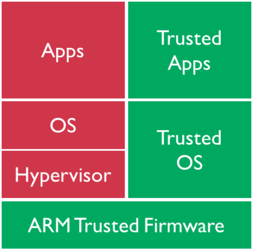
English-source TrustZone architecture diagram
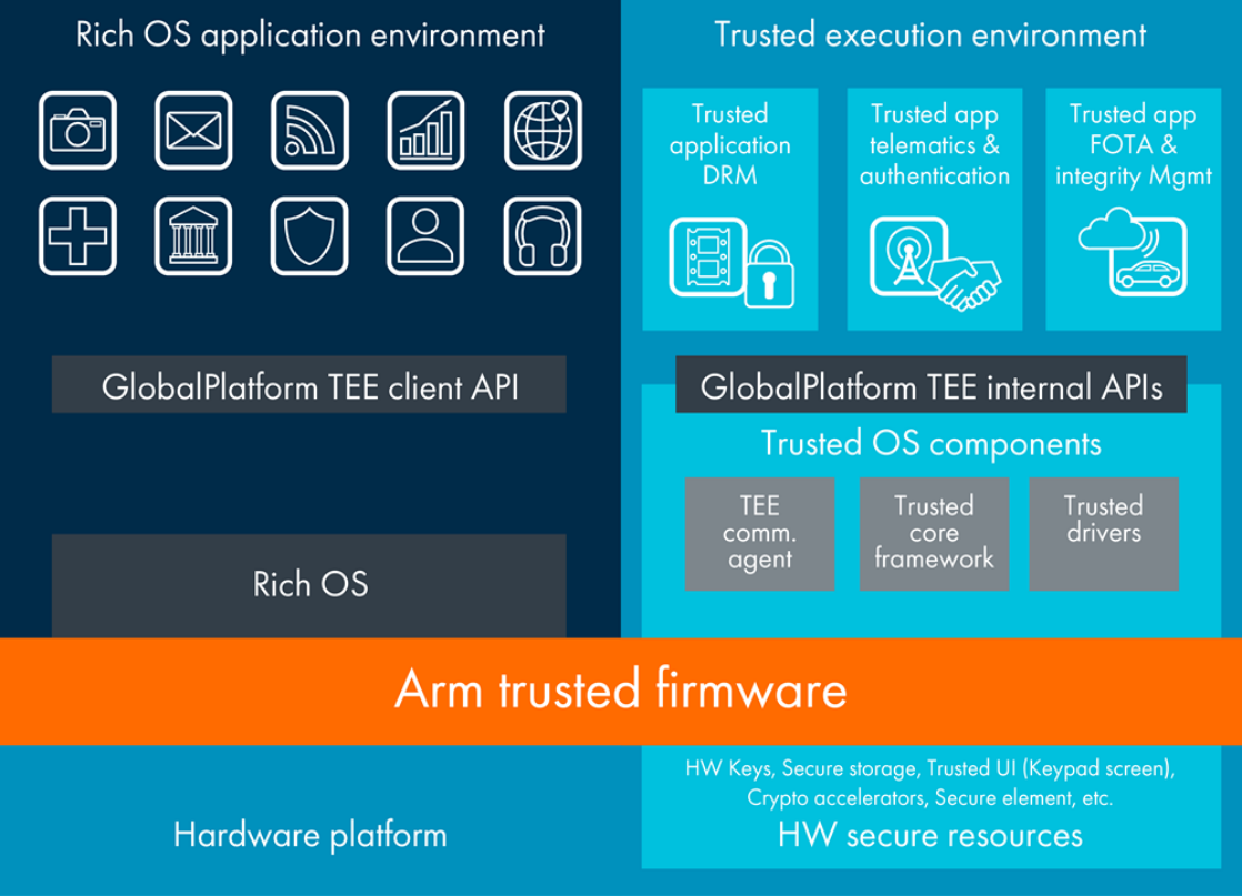
English-source TrustZone architecture diagram
1.2 CPU privilege levels
The next diagram shows CPU privilege modes with TrustZone. A 64-bit CPU has EL0, EL1, EL2 and EL3; depending on its world, EL0/EL1 are secure or non-secure. A 32-bit CPU has Mon, Hyp, SVC, ABT, IRQ, FIQ, UND, SYS and USER modes; SVC, ABT, IRQ, FIQ, UND, SYS and USER likewise have secure/non-secure variants. Rockchip Trust can be understood as EL3 plus secure EL1.
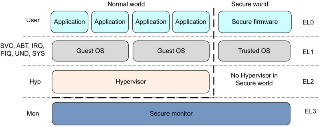
English-source TrustZone architecture diagram
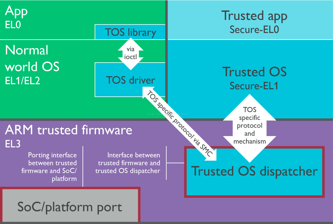
English-source TrustZone architecture diagram
2. Trust on Rockchip platforms
2.1 Implementation
The described Rockchip 64-bit SoCs use ARM Trusted Firmware together with OP-TEE OS; 32-bit SoCs use OP-TEE OS.
2.2 Boot flow
ARM Trusted Firmware describes EL0, EL1, EL2 and EL3 and boot stages BL1, BL2, BL31, BL32 and BL33. Its own source provides BL1, BL2 and BL31. Rockchip uses only its BL31 implementation and supplies its own BL1/BL2. Thus ARM Trusted Firmware commonly means BL31 on Rockchip, while BL32 is OP-TEE OS. Mapping to Rockchip firmware: Maskrom (BL1), Loader (BL2), Trust (BL31: ARM Trusted Firmware + BL32: OP-TEE OS), U-Boot (BL33). Android firmware boot order:
Maskrom -> Loader -> Trust -> U-Boot -> kernel -> Android
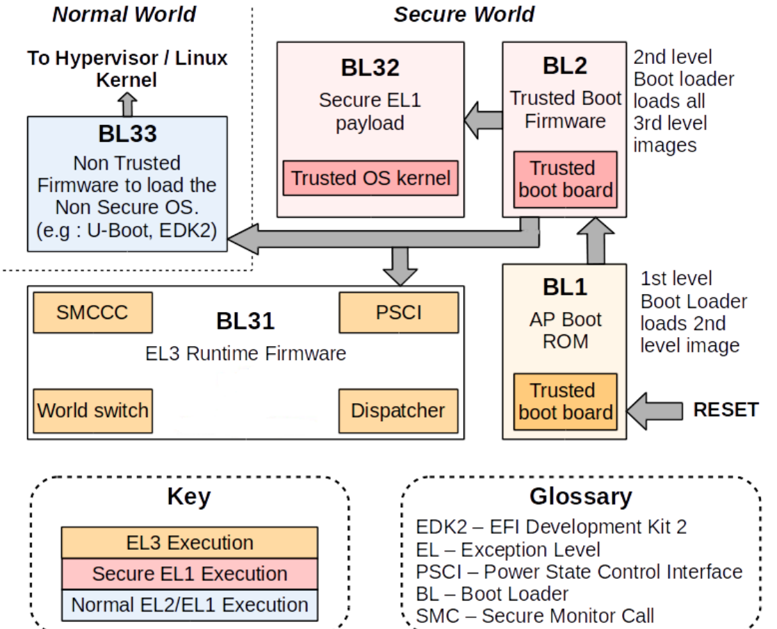
English-source TrustZone architecture diagram
2.3 Obtaining firmware
The source describes distribution as binaries without full source code. Trust binaries are located in the U-Boot project:
./tools/rk_tools/bin/rk30/
./tools/rk_tools/bin/rk31/
./tools/rk_tools/bin/rk32/
./tools/rk_tools/bin/rk33/
When uboot.img is built for a platform, its trust.img is packaged into the U-Boot root directory at the same time. An ini file indexes the binaries for packaging trust.img. These ini files are in the U-Boot project:
tools/rk_tools/RKTRUST/
Developers may also download the separate rkbin repository, containing platform bin files.
2.4 Enabling through DTS
2.4.1 Kernel 3.10
2.4.1.1 32-bit platforms
(1) Add a psci node:
psci {
    compatible      = "arm,psci";
    method          = "smc";
    cpu_suspend     = <0x84000001>;
    cpu_off         = <0x84000002>;
    cpu_on          = <0x84000003>;
    affinity_info   = <0x84000004>;
};
(2) Add psci=enable to chosen or parameter.
chosen {
    bootargs = "psci=enable vmalloc=496M cma=4M rockchip_jtag";
};
2.4.1.2 64-bit platforms
(1) Add a psci node:
psci {
        compatible = "arm,psci-0.2";
        method = "smc";
};
(2) Add enable-method = “psci”; under the cpu node.
cpus {
        #address-cells = <2>;
        #size-cells = <0>;

        cpu@0 {
                device_type = "cpu";
                compatible = "arm,cortex-a53", "arm,armv8";
                reg = <0x0 0x0>;
                enable-method = "psci";
                cpu-idle-states = <&CPU_SLEEP>;
        };
        cpu@1 {
                device_type = "cpu";
                compatible = "arm,cortex-a53", "arm,armv8";
                reg = <0x0 0x1>;
                enable-method = "psci";
                cpu-idle-states = <&CPU_SLEEP>;
        };
        cpu@2 {
                device_type = "cpu";
                compatible = "arm,cortex-a53", "arm,armv8";
                reg = <0x0 0x2>;
                enable-method = "psci";
                cpu-idle-states = <&CPU_SLEEP>;
        };
        cpu@3 {
                device_type = "cpu";
                compatible = "arm,cortex-a53", "arm,armv8";
                reg = <0x0 0x3>;
                enable-method = "psci";
                cpu-idle-states = <&CPU_SLEEP>;
        };

        .....
};
2.4.2 Kernel 4.4+
2.4.2.1 32-bit platforms
Add the psci node:
psci {
        compatible = "arm,psci-1.0";
        method = "smc";
};
2.4.2.2 64-bit platforms
(1) Add a psci node:
psci {
        compatible = "arm,psci-1.0";
        method = "smc";
};
(2) Add enable-method = “psci”; under the cpu node.
cpus {
        #address-cells = <2>;
        #size-cells = <0>;

        cpu@0 {
                device_type = "cpu";
                compatible = "arm,cortex-a53", "arm,armv8";
                reg = <0x0 0x0>;
                enable-method = "psci";
                cpu-idle-states = <&CPU_SLEEP>;
        };
        cpu@1 {
                device_type = "cpu";
                compatible = "arm,cortex-a53", "arm,armv8";
                reg = <0x0 0x1>;
                enable-method = "psci";
                cpu-idle-states = <&CPU_SLEEP>;
        };
        cpu@2 {
                device_type = "cpu";
                compatible = "arm,cortex-a53", "arm,armv8";
                reg = <0x0 0x2>;
                enable-method = "psci";
                cpu-idle-states = <&CPU_SLEEP>;
        };
        cpu@3 {
                device_type = "cpu";
                compatible = "arm,cortex-a53", "arm,armv8";
                reg = <0x0 0x3>;
                enable-method = "psci";
                cpu-idle-states = <&CPU_SLEEP>;
        };

        .....
};
2.4.3 Kernel documentation
Kernel documentation provides PSCI explanations at:
./Documentation/devicetree/bindings/arm/psci.txt
2.5 Runtime memory and lifetime
2.5.1 Runtime memory
ARM Trusted Firmware runs at DRAM offsets 0M–2M, with entry address 0x10000 (64KB). OP-TEE OS runs at DRAM offsets 132M–148M, with its end address varying by platform requirements, and entry address 0x08400000 (132M).
2.5.2 Lifetime
After power-on initialization, Trust remains resident in memory throughout operation.
2.6 Security
With TrustZone, firmware is divided between secure and non-secure worlds. On Rockchip, Loader and Trust run in the secure world; U-Boot, kernel and Android run in the non-secure world, except secure drivers and applications.
2.7 Functions
2.7.1 PSCI(Power State Coordination Interface)
SoC IC designs differ substantially, particularly CPU power management. Vendor-specific software sequences fragment kernel code and are difficult to unify. Ordinary developers also rarely need these implementation details, which depend closely on CPU architecture and IC design and are hard to understand or implement fully. The kernel therefore prefers moving CPU power management into vendor firmware while retaining control policy, making kernel code more uniform. PSCI (Power State Coordination Interface) [3] was introduced for this purpose. It provides CPU-core power-management interfaces that use ARM SMC instructions to enter Trust for CPU on/off, deep system suspend, reset, shutdown and other operations. Main interfaces:
PSCI_VERSION
PSCI_FEATURES
CPU_ON
CPU_OFF
CPU_SUSPEND
SYSTEM_SUSPEND
AFFINITY_INFO
SYSTEM_OFF
SYSTEM_RESET
......
Kernel 4.4+ code paths
./arch/arm/kvm/psci.c
./arch/arm/kernel/smccc-call.S
./arch/arm64/kernel/psci.c
./arch/arm64/kernel/smccc-call.S
./drivers/firmware/psci.c
./drivers/firmware/rockchip_sip.c
Kernel 3.10 code paths
./arch/arm/kernel/psci.c
./arch/arm64/kernel/psci.c
./arch/arm/mach-rockchip/psci.c
2.7.2 Secure Monitor
Secure Monitor bridges CPU state changes between the secure and non-secure worlds. It is implemented in Trust; without it, the CPU could not switch security states and TrustZone would lose its purpose. Entry uses the SMC instruction. The ARM manual explains that the Secure Monitor Call exception is part of the Security Extensions only; SMC requests a Secure Monitor function and causes entry to Monitor mode.
2.7.3 Security configuration
Beyond Cortex-A integration, TrustZone extends through AMBA AXI and dedicated system IP. Security settings for these related IP modules must therefore be configured, generally in Trust.
2.7.4 Protection of secure data
Secure-data protection includes storage protection for secure-payment, DRM, enterprise-service and web-service security information.
3. Troubleshooting Rockchip Trust
The source describes publicly supplied Trust firmware as binary-only. Debugging options are limited and often require dedicated JTAG tools. Ordinary users generally cannot debug and resolve Trust failures themselves, so preserve the failure state and collect sufficient information for the Trust maintainer. Users should recognize Trust messages, firmware versions and PANIC information.
3.1 Boot-log example
NOTICE:  BL31: v1.3(debug):4c793da
NOTICE:  BL31: Built : 18:13:44, Dec 25 2017
NOTICE:  BL31:Rockchip release version: v1.3
INFO:    ARM GICv2 driver initialized
INFO:    Using opteed sec cpu_context!
INFO:    boot cpu mask: 1
INFO:    plat_rockchip_pmu_init: pd status 0xe
INFO:    BL31: Initializing runtime services
INFO:    BL31: Initializing BL32
INF [0x0] TEE-CORE:init_primary_helper:337: Initializing (1.1.0-127-g27532f4 #54
Mon Dec 18 02:01:14 UTC 2017 aarch64)
INF [0x0] TEE-CORE:init_primary_helper:338: Release version: 1.4
INF [0x0] TEE-CORE:init_teecore:83: teecore inits done
INFO:    BL31: Preparing for EL3 exit to normal world
INFO:    Entry point address = 0x200000
INFO:    SPSR = 0x3c9
3.2 Identifying log messages
Apart from boot messages, ARM Trusted Firmware generally uses this runtime format without timestamps:
INFO: *********
OP-TEE OS format, without timestamps:
INF [0x0] TEE-CORE: *********
3.3 Identifying firmware versions
ARM Trusted Firmware version: 4c793da.
NOTICE: BL31: v1.3(debug):4c793da
OP-TEE OS version: 27532f4 (ignore the leading g).
INF [0x0] TEE-CORE:init_primary_helper:337: Initializing (1.1.0-127-g27532f4 #54
Mon Dec 18 02:01:14 UTC 2017 aarch64)
3.4 Identifying PANIC messages
3.4.1 ARM Trusted Firmware panic
Unhandled Exception in EL3.
x30 =           0x00000000ff00fff0
x0 =            0x00000000000101c0
x1 =            0x0000000000000000
x2 =            0x0000000000000000
x3 =            0x0000000000000000
x4 =            0x0000000000cd383b
x5 =            0x0000000000080001
x6 =            0x0000000080803520
x7 =            0x00000000000342a0
x8 =            0x00000000000101c0
x9 =            0x0000000000000000
x10 =           0x0000000000000000
x11 =           0x0000000000000000
x12 =           0x0000000000000001
x13 =           0x00000000000101b8
x14 =           0x000000000001a950
x15 =           0x0000000000000000
x16 =           0x00000000000101c0
x17 =           0x0000000000000000
x18 =           0x0000000000000000
x19 =           0x0000000000000000
x20 =           0x0000000040000000
x21 =           0x0000000000000040
x22 =           0x00000000000305b0
x23 =           0x000000000001016c
x24 =           0x00000000000101c0
x25 =           0x0000000000000000
x26 =           0x0000000000000000
x27 =           0x0000000000000000
x28 =           0x0000000000035bf8
x29 =           0x0000000000000000
scr_el3 =       0x00000000000101c0
sctlr_el3 =     0x0000000000000000
cptr_el3 =      0x0000000000000000
tcr_el3 =       0x0000000000000000
daif =          0x0000000000000238
mair_el3 =      0x0000000000cd383b
spsr_el3 =      0x0000000000000000
elr_el3 =       0x0000000080803520
ttbr0_el3 =     0x00000000000101c0
esr_el3 =       0x0000000000000000
far_el3 =       0x0000000000000000
spsr_el1 =      0x00000000000101c0
elr_el1 =       0x0000000000000000
spsr_abt =      0x0000000000000000
......
3.4.2 OP-TEE OS panic
core data-abort at address 0xc121b16c

 fsr 0x00000805  ttbr0 0x6847446a  ttbr1 0x6847006a  cidr 0x2
 cpu #0          cpsr 0x200001d1
 r0 0x20068000      r4 0x68407195    r8 0x00000000   r12 0x00000000
 r1 0x00000049      r5 0x6848068b    r9 0x6840a3bd    sp 0xc121b1a4
 r2 0x6848068c      r6 0x6848068c   r10 0x684808cc    lr 0x684296a6
 r3 0x0000001f      r7 0x00000001   r11 0x68404f9d    pc 0x6840041c

ERR [0x0] TEE-CORE:tee_pager_handle_fault:125: Unexpected page fault! Trap CPU
PANIC: tee_pager_handle_fault core/arch/arm/include/mm/tee_pager.h:126
4. Appendix: references
[0] Open-source downloads:
ARM Trusted Firmware:https://github.com/ARM-software/arm-trusted-firmware
OP-TEE OS:https://github.com/OP-TEE/optee_os
[1] ARM TrustZone:
https://www.arm.com/products/security-on-arm/trustzone
https://developer.arm.com/technologies/trustzone
[2] OP-TEE website: https://www.op-tee.org/
[3] PSCI:http://infocenter.arm.com/help/topic/com.arm.doc.den0022c/DEN0022C_Power_State_Coordination_Interface.pdf “Power State Coordination Interface PDD (ARM DEN 0022C)”