
This guide covers PIN-CTRL and DTS, using Chinese V1.0.0 as the approved common baseline and translating its additional material. Chinese ID RK-KF-YF-200; English ID RK-KF-YF-136. Scope: Linux-4.19 on RK3568/RK3399/RK3368/RK3288/PX30/RK3128/RK3126/RV1126; Linux-5.10 on RK3588/RV1106. Platform reference only: verify the actual ArmSoM board pins, VCCIO, SDK/BSP, kernel and TRM. No hardware validation. This version uses the English PDF original figure.
Conflicts retained: Chinese per-port pin index is 0–7; English says 0–31. Chinese says mA before RK3399 and Level after RK1808; English says mA before RK1808 and Level from RK3399. The body retains Chinese wording, not verified chip behavior: consult the specific TRM and driver. Chinese-only driver details, SMT, init transitions, PWM and FAQ 4.2/4.3 are translated. Source rockchip,pin (singular), 2cm0 and the init/default parenthesis remain unresolved, not silently corrected.
ArmSoM Docs · Rockchip Linux kernel
1 Pin naming rules
A Rockchip pin ID consists of controller (bank), port and pin index.
1.1 GPIO
The number of banks equals the number of GPIO controllers. Ports are A, B, C and D; the per-port pin index is 0, 1, 2, 3, 4, 5, 6 or 7. For example, Chapter 20 GPIO of RK3588-TRM.pdf states: There are five GPIOs (GPIO0 in PD_PMU, GPIO1/GPIO2/GPIO3/GPIO4 in PD_BUS). Each of the five controllers controls 32 IOs. In GPIO mode, GPIO controller registers configure port behavior.
1.2 IOMUX
A Rockchip pin can serve multiple functions. Alternative pin routes for one controller are usually called m0, m1, m2, etc. For example, an I2C controller with two routes has 2cm0 and i2cm1 (source spelling retained). Pinmux registers reside in GRF/PMUGRF, called IOC on RK3588. RK3588 example:
BUS_IOC_GPIO1B_IOMUX_SEL_H
Address: Operational Base + offset (0x002C)
gpio1b7_sel
4'h0: GPIO
4'h2: MIPI_CAMERA2_CLK_M0
4'h3: SPDIF1_TX_M0
4'h4: PCIE30X2_PERSTN_M3
4'h5: HDMI_RX_CEC_M2
4'h6: SATA2_ACT_LED_M1
4'h9: I2C5_SDA_M3
4'ha: UART1_RX_M1
4'hb: PWM13_M2
RK3588 I2C5 IOMUX is shown below.
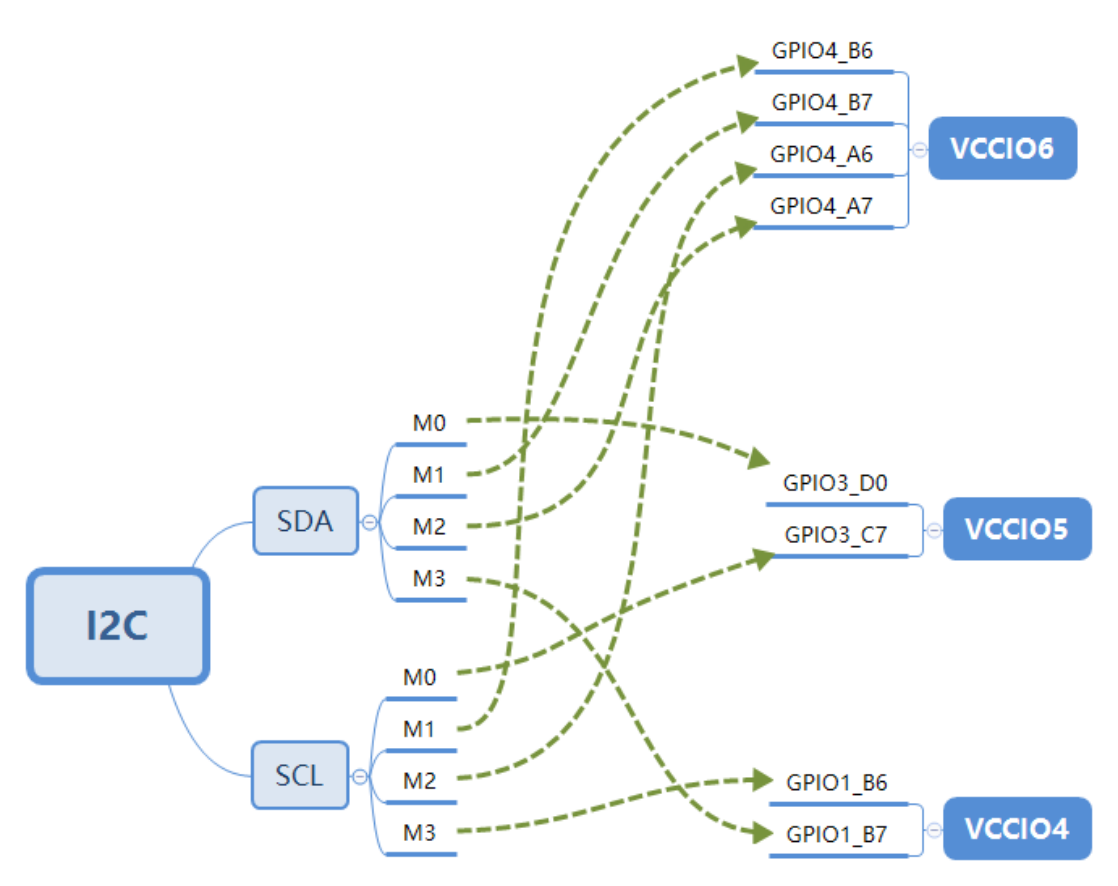
RK3588 I2C5 routing, English source figure
Multiple routes allow more flexible hardware design: for peripherals operating at 1.8V or 3.3V, pins in different VCCIO voltage domains can be selected. Note: the route-selection register setting affects RX-type pins, not TX-type pins.
1.3 PULL
Rockchip IO PAD bias normally supports three modes: bias-disable, bias-pull-up, bias-pull-down. Pull configuration acts on the IO PAD and therefore applies in both GPIO and IOMUX modes.
1.4 DRIVE-STRENGTH
Supported IO PAD drive strengths depend on the process technology. The Chinese source says chips before RK3399 configure strength in mA, while chips after RK1808 generally use Level, whose numeric value is the register setting. RK3588 TRM gives the following GPIO0_C7 example (gpio0c7_ds, GPIO0C7 DS control Driver Strength Selection):
3'b000: 100ohm
3'b100: 66ohm
The remaining strengths and their driver-level mappings are:
3'b010: 50ohm
3'b110: 40ohm
3'b001: 33ohm
3'b101: 25ohm

3'b000: Level0
3'b100: Level4
3'b010: Level2
3'b110: Level6
3'b001: Level1
3'b101: Level5
In DTS, drive-strength=<5>; selects Level5, writing 3'b101 to the register.
1.5 SMT (Schmitt trigger)
Most Rockchip chips support IO PAD SMT, disabled by default. Enabling it suppresses edge jitter, widens the VIH/VIL voltage interval and improves signal stability. I2C SCL/SDA normally enable SMT by default.
2 Driver introduction
Rockchip pinctrl consists of the Pinctrl driver (drivers/pinctrl/pinctrl-rockchip.c) and GPIO driver (drivers/gpio/gpio-rockchip.c). Pinctrl is the primary driver and exposes IO operations for PINMUX, PINCONF and GPIO. The GPIO driver implements gpiochip functionality, including GPIO and IRQ.
2.1 pinctrl-rockchip
//TO-DO — the source provides no implementation detail here.
2.2 gpio-rockchip
//TO-DO — the source provides no implementation detail here.
3 DTS introduction
Rockchip DTS normally places the pinctrl node in soc.dtsi, for example rk3588s.dtsi, usually as the last node.
The pinctrl node has no reg and is not a standard platform device. Its register base is supplied through rockchip,grf=<&grf>;. The driver adds offsets to this base to configure IOMUX and PINCONF. GPIO uses the gpio node reg address. Example: arch/arm64/boot/dts/rockchip/rk3588s.dtsi.
{
    pinctrl: pinctrl {
        compatible = "rockchip,rk3588-pinctrl";
        rockchip,grf = <&ioc>;
        #address-cells = <2>;
        #size-cells = <2>;
        ranges;

        gpio0: gpio@fd8a0000 {
            compatible = "rockchip,gpio-bank";
            reg = <0x0 0xfd8a0000 0x0 0x100>;
            interrupts = <GIC_SPI 277 IRQ_TYPE_LEVEL_HIGH>;
            clocks = <&cru PCLK_GPIO0>, <&cru DBCLK_GPIO0>;

            gpio-controller;
            #gpio-cells = <2>;
            interrupt-controller;
            #interrupt-cells = <2>;
        };

        gpio1: gpio@fec20000 {
            compatible = "rockchip,gpio-bank";
            reg = <0x0 0xfec20000 0x0 0x100>;
            interrupts = <GIC_SPI 278 IRQ_TYPE_LEVEL_HIGH>;
            clocks = <&cru PCLK_GPIO1>, <&cru DBCLK_GPIO1>;

            gpio-controller;
            #gpio-cells = <2>;
            interrupt-controller;
            #interrupt-cells = <2>;
        };

        gpio2: gpio@fec30000 {
            compatible = "rockchip,gpio-bank";
            reg = <0x0 0xfec30000 0x0 0x100>;
            interrupts = <GIC_SPI 279 IRQ_TYPE_LEVEL_HIGH>;
            clocks = <&cru PCLK_GPIO2>, <&cru DBCLK_GPIO2>;

            gpio-controller;
            #gpio-cells = <2>;
            interrupt-controller;
            #interrupt-cells = <2>;
        };

        gpio3: gpio@fec40000 {
            compatible = "rockchip,gpio-bank";
            reg = <0x0 0xfec40000 0x0 0x100>;
            interrupts = <GIC_SPI 280 IRQ_TYPE_LEVEL_HIGH>;
            clocks = <&cru PCLK_GPIO3>, <&cru DBCLK_GPIO3>;
            gpio-controller;
            #gpio-cells = <2>;
            interrupt-controller;
            #interrupt-cells = <2>;
        };

        gpio4: gpio@fec50000 {
            compatible = "rockchip,gpio-bank";
            reg = <0x0 0xfec50000 0x0 0x100>;
            interrupts = <GIC_SPI 281 IRQ_TYPE_LEVEL_HIGH>;
            clocks = <&cru PCLK_GPIO4>, <&cru DBCLK_GPIO4>;

            gpio-controller;
            #gpio-cells = <2>;
            interrupt-controller;
            #interrupt-cells = <2>;
        };
    };
};
The file arch/arm64/boot/dts/rockchip/rk3588s-pinctrl.dtsi is also included in rk3588s.dtsi.
3.1 Create pinctrl instances
rk3588s-pinctrl.dtsi already enumerates all RK3588s IOMUX instances; modules normally do not need to create new ones. New instances must follow these rules:
-
Place it under the pinctrl node.
-
Add it in function + group form.
-
The function + group format is:
function {
    group {
        rockchip,pin = <bank gpio func &ref>;
    };
};
- Follow the other basic DTS rules.
3.2 Reference pinctrl
A module references pinctrl through pinctrl-names and pinctrl-0, linking the module to the pinctrl driver. RK3588 uart2 example:
{
    uart2: serial@feb50000 {
        compatible = "rockchip,rk3588-uart", "snps,dw-apb-uart";
        reg = <0x0 0xfeb50000 0x0 0x100>;
        interrupts = <GIC_SPI 333 IRQ_TYPE_LEVEL_HIGH>;
        clocks = <&cru SCLK_UART2>, <&cru PCLK_UART2>;
        clock-names = "baudclk", "apb_pclk";
        reg-shift = <2>;
        reg-io-width = <4>;
        dmas = <&dmac0 10>, <&dmac0 11>;
        pinctrl-names = "default";
        pinctrl-0 = <&uart2m1_xfer>;
        status = "disabled";
    };
};
uart2m1_xfer is a pinctrl group. A module can reference several groups simultaneously. RK3588 pdm1 example:
{
    pdm1: pdm@fe4c0000 {
        compatible = "rockchip,rk3588-pdm";
        reg = <0x0 0xfe4c0000 0x0 0x1000>;
        clocks = <&cru MCLK_PDM1>, <&cru HCLK_PDM1>;
        clock-names = "pdm_clk", "pdm_hclk";
        assigned-clocks = <&cru MCLK_PDM1>;
        assigned-clock-parents = <&cru PLL_AUPLL>;
        dmas = <&dmac1 4>;
        dma-names = "rx";
        power-domains = <&power RK3588_PD_AUDIO>;
        pinctrl-names = "default";
        pinctrl-0 = <&pdm1m0_clk
                 &pdm1m0_clk1
                 &pdm1m0_sdi0
                 &pdm1m0_sdi1
                 &pdm1m0_sdi2
                 &pdm1m0_sdi3>;
/* 等同于如下写法 */
/*
 *      pinctrl-0 = <&pdm1m0_clk>,
 *                  <&pdm1m0_clk1>,
 *                  <&pdm1m0_sdi0>,
 *                  <&pdm1m0_sdi1>,
 *                  <&pdm1m0_sdi2>,
 *                  <&pdm1m0_sdi3>;
 */
        #sound-dai-cells = <0>;
        status = "disabled";
    };
};
pinctrl-names supports multiple states. Pinctrl defines four standard states:
#define PINCTRL_STATE_DEFAULT "default"
#define PINCTRL_STATE_INIT "init"
#define PINCTRL_STATE_IDLE "idle"
#define PINCTRL_STATE_SLEEP "sleep"
“init” applies during driver probe; after probe it may switch back to “default”. The source parenthesis says that if probe selects another state, it will not switch back to “init”; this wording is retained for verification. pinctrl-names can be customized and must be matched and parsed by the driver. RK3588 pwm4 example:
{
    pwm4: pwm@febd0000 {
        compatible = "rockchip,rk3588-pwm", "rockchip,rk3328-pwm";
        reg = <0x0 0xfebd0000 0x0 0x10>;
        #pwm-cells = <3>;
        pinctrl-names = "active";
        pinctrl-0 = <&pwm4m0_pins>;
        clocks = <&cru CLK_PWM1>, <&cru PCLK_PWM1>;
        clock-names = "pwm", "pclk";
        status = "disabled";
    };
};
4 FAQ
4.1 Configure IOMUX from userspace
iomux is a gcc-built binary that uses ioctl on the rockchip-pinctrl device to set or read the current IOMUX value. Build:
gcc tools/testing/selftests/rkpinctrl/iomux.c -o iomux
Usage example: set GPIO0_B7 to func1.
[root@RK3588:/]# iomux 0 15 1
Example: read the current GPIO0_B7 IOMUX value.
[root@RK3588:/]# iomux 0 15
mux get (GPIO0-15) = 1
4.2 Set a GPIO level
A GPIO may not belong to a particular module but instead act as a power switch, requiring a high or low level as early as possible during boot. Use “regulator-fixed”, normally used for a fixed-voltage regulator or one switched by a GPIO. Example: configure GPIO2_A1 high.
/ {
    foo_name: foo-name {
        compatible = "regulator-fixed";
        pinctrl-names = "default";
        pinctrl-0 = <&gpio_foo>;
        regulator-name = "vcc-foo";
        regulator-always-on;
    };
};

&pinctrl {
    gpio-foo {
        gpio_foo: gpio-foo {
            rockchip,pins = <2 RK_PA1 RK_FUNC_GPIO &pcfg_output_high>;
        };
    };
};
4.3 Module pinctrl-0 has no effect
Modules normally use pinctrl-names and pinctrl-0 to configure default IOMUX or IOCONFIG, but these properties cannot be added indiscriminately to all nodes. A module invoked by driver_probe_device can use them. For debugging, add logging to pinctrl_bind_pins in drivers/base/dd.c to inspect the calls.