
Complete technical translation of Chinese RK-KF-YF-175 V1.1.0, pages 4–8. The source applies to RK3399 and kernels 4.4/4.19. This is a platform reference; no matching ArmSoM board is confirmed and support is not extended to all ArmSoM boards or other SoCs. Verify the actual SDK/BSP, PCIe pins, power, device tree and peripheral drivers for the board. Only the Chinese PDF is available; all four languages use its figures. Table results are vendor RK3399 EVB3 examples, not ArmSoM measurements. No hardware validation was performed.
Retained source issues: the DTS notation
status = <okay>;and the supply referencevpcie0v9-supply = <&vdd_pcie1v8>;must be checked against the actual BSP/schematic, not copied blindly. Lane interchange, power and bandwidth statements are source claims; the vendor explicitly did not test lane interchange. The fio write test below overwrites the target block device; do not run it on a device containing data. Later voltage-increase suggestions are not safe operating instructions; never exceed board/component specifications.
ArmSoM Docs · Rockchip Linux kernel
1. DTS configuration
-
ep-gpios = <&gpio3 13 GPIO_ACTIVE_HIGH>;configures the PCIe PERST# reset signal. Whether the device is plugged into a slot or soldered down, locate this pin in the schematic and configure it correctly; otherwise link establishment will fail. -
num-lanes = <4>;sets the number of lanes used by the PCIe device. Normally no adjustment is needed: the software detects and disables unused lanes to save power. -
status = <okay>;is the exact notation in the source. Enable bothpcie0andpcie_phy. They are disabled by default because PCIe detection adds a substantial boot delay when no peripheral is attached. Projects needing PCIe must enable them. See the editorial note about the source syntax before using it. -
vpcie3v3-supply = <&vdd_pcie3v3>;is optional and configures the peripheral’s 3V3 supply. If the board must control that supply’s enable signal, define the corresponding regulator as in the example. Refer toDocumentation/devicetree/bindings/regulator/for regulator configuration. -
vpcie1v8-supply = <&vdd_pcie1v8>;— see item 4. -
vpcie0v9-supply = <&vdd_pcie1v8>;— see item 4. This source value is retained, not confirmed as the correct board supply.
2. menuconfig configuration
- Enable the following options for PCIe functionality:
CONFIG_PCI=y
CONFIG_PCI_DOMAINS=y
CONFIG_PCI_DOMAINS_GENERIC=y
CONFIG_PCI_SYSCALL=y
CONFIG_PCI_BUS_ADDR_T_64BIT=y
CONFIG_PCI_MSI=y
CONFIG_PCI_MSI_IRQ_DOMAIN=y
CONFIG_PHY_ROCKCHIP_PCIE=y
CONFIG_PCIE_ROCKCHIP=y
CONFIG_PCIEPORTBUS=y
CONFIG_PCIEASPM=y
CONFIG_PCIEASPM_POWERSAVE=y
CONFIG_PCIE_PME=y
CONFIG_GENERIC_MSI_IRQ=y
CONFIG_GENERIC_MSI_IRQ_DOMAIN=y
CONFIG_IRQ_DOMAIN=y
CONFIG_IRQ_DOMAIN_HIERARCHY=y
- Enable NVMe devices (PCIe-connected SSDs):
CONFIG_BLK_DEV_NVME=y
- Enable AHCI devices (SATA SSDs behind a PCIe-to-SATA adapter):
CONFIG_SATA_PMP=y
CONFIG_SATA_AHCI=y
CONFIG_SATA_AHCI_PLATFORM=y
CONFIG_ATA_SFF=y
CONFIG_ATA=y
Note: the default open-source 4.4 kernel supports only the devices listed in drivers/ata/ahci.c. For other devices, contact the device manufacturer or distributor.
- For PCIe Wi-Fi configuration, consult the respective Wi-Fi vendor documentation.
3. Kernel command-line configuration
Refer to Documentation/kernel-parameters.txt in the kernel for details. Only a few important parameters are described here.
-
nomsi: addpci=nomsito parameter to use Legacy interrupts. -
pcie_bus_safe: the source says that settingpci=pcie_bus_safeadjusts the maximum payload size (MPS) across the PCIe hierarchy to its maximum and can improve bandwidth. This description is retained as a source claim; check the actual kernel implementation and device limits. -
pcie_aspm: setpcie_aspm=offto disable dynamic link power management for testing. Otherwise the default configuration follows hardware negotiation.
4. Frequently asked application questions
Q1: Can lanes be interchanged to simplify PCB routing?
A1: The source says this is theoretically possible: RC lanes [1–4] can correspond arbitrarily to EP/switch lanes [1–4], without software changes. The vendor explicitly states this was not actually verified; evaluate cautiously.
Q2: Can the differential polarity within one lane be interchanged?
For example, RC lane1 RX+ to EP/switch RX-, TX+ to TX-, or other RX/TX polarity combinations?
A2: The source permits these combinations without additional software handling; the PCIe detection state machine accounts for them.
Q3: Can RK3399’s four lanes be split into 1-1-1-1, 2-2 or another combination?
A3: RK3399 has one RC and does not support this bifurcation. Use a PCIe switch for multiple devices. The vendor reported testing a Pericom switch and described it as probably the cheapest option at that time; this is a historical source statement, not a current price recommendation.
Q4: Does RK3399 support SSDs?
A4: The source distinguishes NVMe SSDs, using PCIe at the physical interface, from mSATA SSDs, using SATA. For the latter, use a PCIe-to-SATA or USB-to-SATA adapter.
Q5: What is the maximum NVMe capacity, and can it be a boot drive?
A5: The source attributes the capacity limit to the filesystem rather than the driver. RK3399 can start NVMe boot support from U-Boot, requiring an additional SPI-NOR to hold miniloader because MaskROM has no NVMe or PCIe driver.
Q6: What bandwidth is achieved with an NVMe device, and how is it tested?
A6: The vendor used fio. Build your own fio with libaio statically linked. The original command and vendor results follow; these are not ArmSoM measurements.
./fio -filename=/dev/block/nvme0n1 -direct=1 -iodepth 4 -thread=1 -rw=write -ioengine=libaio -bs=1M -size=200G -numjobs=30 -runtime=60 -group_reporting -name=my
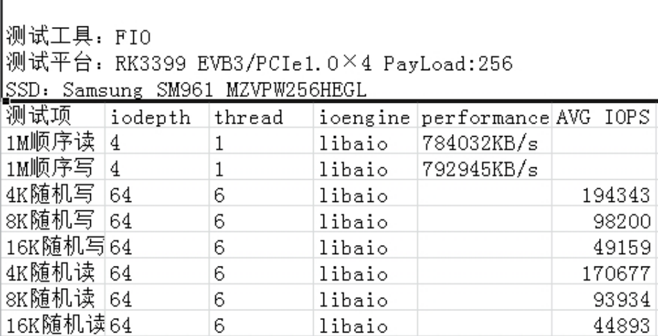
FIO · RK3399 EVB3 · PCIe1.0×4 · Payload:256 · SSD: Samsung SM961 MZVPW256HEGL
| Test | iodepth | thread | ioengine | performance | AVG IOPS |
|---|---|---|---|---|---|
| 1M sequential read | 4 | 1 | libaio | 784032KB/s | |
| 1M sequential write | 4 | 1 | libaio | 792945KB/s | |
| 4K random write | 64 | 6 | libaio | 194343 | |
| 8K random write | 64 | 6 | libaio | 98200 | |
| 16K random write | 64 | 6 | libaio | 49159 | |
| 4K random read | 64 | 6 | libaio | 170677 | |
| 8K random read | 64 | 6 | libaio | 93934 | |
| 16K random read | 64 | 6 | libaio | 44893 |
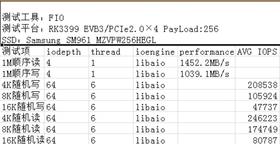
FIO · RK3399 EVB3 · PCIe2.0×4 · Payload:256 · SSD: Samsung SM961 MZVPW256HEGL
| Test | iodepth | thread | ioengine | performance | AVG IOPS |
|---|---|---|---|---|---|
| 1M sequential read | 4 | 1 | libaio | 1452.2MB/s | |
| 1M sequential write | 4 | 1 | libaio | 1039.1MB/s | |
| 4K random write | 64 | 6 | libaio | 208538 | |
| 8K random write | 64 | 6 | libaio | 105924 | |
| 16K random write | 64 | 6 | libaio | 47737 | |
| 4K random read | 64 | 6 | libaio | 246223 | |
| 8K random read | 64 | 6 | libaio | 174749 | |
| 16K random read | 64 | 6 | libaio | 80787 |
Q7: Does RK3399 support a discrete GPU?
A7: Theoretically yes if an ARM driver is available, but the source says it is not practical: only 32M of physical PCIe bus address space is available for BARs, less than discrete GPUs normally require. A switch does not solve this; it needs address space itself and increases the RC’s address-space requirement.
Q8: Which power supplies do PCIe devices use?
A8: The source lists 0.9V, 3V3, 3V3_AUX and 12V. It associates 0.9V mainly with PCIe Wi-Fi, and 3V3 with most devices. The auxiliary 3V3_AUX must remain powered during suspend when a device must keep working, for example Wi-Fi waking the host. 12V is used by higher-power devices such as switches and GPUs. Follow the actual EP/switch manufacturer’s requirements.
Q9: How can ASPM be controlled on RK3399?
A9: Five methods are given:
- Add
pcie_aspm=offto the kernel command line. - Configure
link_stateat the console; this requiresCONFIG_PCIEASPM_DEBUG=y:
# cat /sys/bus/pci/devices/0000:00:00.0/power/link_state
7
# echo 0 > /sys/bus/pci/devices/0000:00:00.0/power/link_state
- Disable
CONFIG_PCIEASPM. - Use
setpci, for examplesetpci -s 0:0 0xd0.w=0xC00. Know the target device’s BDF first. - Run
echo performance > /sys/module/pcie_aspm/parameters/policyat the console.
Q10: How can PCIe device information be inspected on RK3399?
A10: The original question spells the chip RK399. Copy lspci to the device and grant execute permission. Common commands are lspci -vvv for properties and operating state and lspci -t for the PCIe topology tree. See lspci --help for other parameters.
Q11: How can PCIe registers be modified from user space?
A11: Use setpci only after obtaining the target BDF with lspci and understanding the relevant register offsets in the protocol. Consult setpci --help. The source calls this an advanced tool and advises against its use without adequate PCIe protocol knowledge.
5. Troubleshooting
5.1 Link training failure
rockchip-pcie f8000000.pcie: PCIe link training gen1 timeout!
rockchip-pcie: probe of f8000000.pcie failed with error -1
The source attributes a training failure to the peripheral not being operational. First check ep-gpios, then whether peripheral power is present and sufficient. It states that 3.3V should theoretically suffice but claims some devices needed 3.8V or even 4V. This is an unverified historical source claim, not an instruction to overvolt a device: do not exceed the board or component limits. Even at sufficient voltage, check available power; the source mentions testing with an external supply. Such testing requires a verified power design and safe voltage limits.
5.2 Hang during configuration
[ 0.459371] pci 0000:00:00.0: bridge configuration invalid ([bus 00-00]), reconfiguring
[ 0.459585] pci 0000:01:00.0: reg 0x10: initial BAR value 0x00000000 invalid
[ 0.460043] pci 0000:01:00.1: reg 0x10: initial BAR value 0x00000000 invalid
[ 0.460503] pci 0000:01:00.2: reg 0x10: initial BAR value 0x00000000 invalid
[ 0.460535] pci 0000:01:00.2: reg 0x14: initial BAR value 0x00000000 invalid
[ 0.460904] Bad mode in Error handler detected, code 0xbf000002 -- SError
[ 0.460919] Internal error: Oops - bad mode: 0 [#1] PREEMPT SMP
[ 0.466658] Modules linked in:
[ 0.466938] CPU: 5 PID: 1 Comm: swapper/0 Not tainted 4.4.55 #41
[ 0.467464] Hardware name: Rockchip RK3399 Excavator Board edp (Android) (DT)
[ 0.468089] task: ffffffc0f2160000 ti: ffffffc0f2168000 task.ti: ffffffc0f2168000
[ 0.468752] PC is at rockchip_pcie_rd_conf+0xb8/0x138
[ 0.469200] LR is at pci_bus_read_config_dword+0x78/0xbc
In this example the device operated and completed enumeration, but communication then hung. The source attributes most such cases to insufficient supply voltage or power.
5.3 RK3399 PCIe PHY PLL does not lock
[ 0.440803] rockchip-pcie f8000000.pcie: no vpcie3v3 regulator found
[ 0.440831] rockchip-pcie f8000000.pcie: no vpcie1v8 regulator found
[ 0.440854] rockchip-pcie f8000000.pcie: no vpcie0v9 regulator found
[ 1.443759] pll lock timeout!
[ 1.443826] phy phy-phy@e220.5: phy poweron failed --> -22
[ 1.443847] rockchip-pcie f8000000.pcie: fail to power on phy, err -22
[ 1.443968] rockchip-pcie: probe of f8000000.pcie failed with error -22
Check whether PCIE_AVDD_0V9 and PCIE_AVDD_1V8 have normal voltage and adequate supply capability. The source specifies an LDO supply for this rail; confirm against the actual board design.
5.4 Errors when PCIe and USB 3.0 operate simultaneously
The following source log records a system error when a USB device was inserted during NVMe operation:
[ 2.801962] Unhandled fault: synchronous external abort (0x96000210) at 0xffffff800936401c
[ 2.801997] Internal error: : 96000210 [#1] PREEMPT SMP
[ 2.803157] Modules linked in:
[ 2.803437] CPU: 2 PID: 146 Comm: nvme Not tainted 4.4.16 #146
[ 2.803949] Hardware name: rockchip,rk3399-firefly-mini (DT)
[ 2.804445] task: ffffffc07187d400 ti: ffffffc071910000 task.ti: ffffffc071910000
[ 2.805108] PC is at nvme_kthread+0x84/0x1f8
[ 2.805484] LR is at nvme_kthread+0x60/0x1f8
The source concludes that PCIE_AVDD_0V9 is insufficient or unstable, and suggests adding capacitance or increasing voltage. This is retained for traceability, not as an approved modification. Verify power integrity and component/board ratings before any hardware change; do not raise voltage beyond specified limits.