
Complete technical translation of Chinese RK-KF-YF-C51 V3.2.0. Source scope: RK3588 Linux 6.1/5.10; RK3568 Linux 6.1/5.10/4.19; RT-Thread is implemented only on the RK PCIe EP side. No English PDF is available; all four languages use Chinese original figures. This is a platform reference. Verify the actual ArmSoM board PCIe routing, power, PERST#/WAKE#, SDK/BSP, Loader and kernel settings. No ArmSoM hardware validation has been performed.
Source issues retained for checking: “1MB(2^0) to 8EB(2^20)” is arithmetically inconsistent; SPL_PCIE_EP_SUPPOR differs from SUPPORT in code; reset-gpios and wake-gpios both use gpio3 13; §1.4 ends incompletely, §7.2.2 has ambiguous diagnostic wording, and §7.2.3 says Host Reset. Do not deploy these examples unchanged. Flashing, OTP, partitions and reset can lose data; no commands were executed.
1 Boot schemes
1.1 Boot scheme comparison
| Scheme | Advantages | Disadvantages |
|---|---|---|
| PCIe Boot | Fast PCIe initialization; no storage; host firmware downloads | Few adjustable PCIe parameters; limited compatibility |
| Flash Boot with PCIe Bin and EP Boot | General RC support; fully adjustable PCIe parameters; small storage; host firmware downloads | Relatively complex software flow |
| Flash Boot with PCIe Bin | General RC support; fully adjustable PCIe parameters; local storage | Large storage |
| Common Boot | Simplest software flow; local storage | Large storage; only specific RCs |
1.2 PCIe Boot
PCIe Boot is the PCIe firmware-loading logic integrated into ROM code. It performs PCIe enumeration and firmware loading: fast PCIe initialization, no storage, and firmware download from the host. Check chip support in “RK SOC PCIe interconnection features”. Because the initialization code is fixed in the mask ROM, most parameters cannot be adjusted; only specific PCIe settings can be changed through OTP. A fixed RC environment is recommended. The flowchart follows.
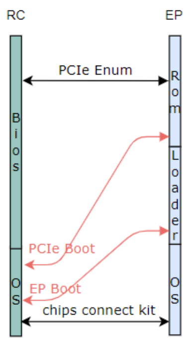
Chinese source flowchart, page 6
Notes: red arrows represent firmware downloads from the host. Main flow: BootROM completes PCIe enumeration and implements PCIe Boot; the host downloads Pre-Loader and BootROM executes it. Loader runs several early firmware components, normally ddr.bin to initialize DDR and loader.bin implementing EP Boot. The host downloads firmware containing later-stage firmware, algorithms and other data, then the later-stage firmware runs. On Linux, loader.bin is spl.bin. OS is the later-stage firmware, running the chip-interconnection chips connectr package in kernel/userspace.
1.3 Flash Boot with PCIe Bin and EP Boot
Flash Boot is the RK SOC SPI Flash boot scheme. On top of SPI Flash Boot, the Loader stage integrates PCIe Bin for fast PCIe initialization and EP Boot logic so that the host can deliver later-stage firmware. The flowchart follows.
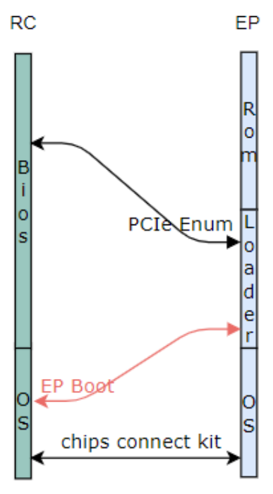
Chinese source flowchart, page 7
Use SPI Flash as boot storage and integrate PCIe Bin for fast PCIe initialization; the host supplies later-stage firmware. Connection to a general-purpose PC is supported.
Red arrows indicate firmware downloads initiated by the host. BootROM loads and runs PCIe Bin/Pre-Loader. PCIe Bin completes PCIe enumeration. Loader executes early firmware, normally pcie.bin for PCIe enumeration, ddr.bin for DDR initialization, and loader.bin with EP Boot. The host downloads fw packet containing later-stage firmware, algorithms and other data, then executes the later-stage firmware. On Linux loader.bin is spl.bin. OS runs the chips connect package in kernel/userspace.
1.4 Flash Boot with PCIe Bin
Flash Boot is the RK SOC SPI Flash boot scheme. In its Loader stage, PCIe Bin provides fast PCIe initialization and supports general-purpose PCs. Local storage is supported: a single-storage scheme loads later-stage firmware from SPI Flash; a dual-storage scheme uses SPI Flash as boot storage together with large-capacity NVMe/eMMC storage, from which
later-stage firmware is loaded. See Rockchip_Developer_Guide_Dual_Storage_CN.pdf for details. The flowchart follows.
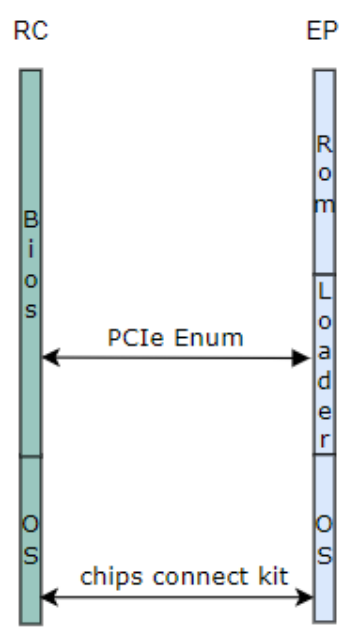
Chinese source flowchart, page 8
Red arrows indicate host firmware downloads. BootROM loads PCIe Bin/Pre-Loader; PCIe Bin completes enumeration. Loader runs pcie.bin for enumeration, ddr.bin for DDR initialization and loader.bin to load subsequent firmware. OS runs chips connect in kernel/userspace. Dual storage is supported with SPI Flash for boot and NVMe/eMMC as main storage; see Rockchip_Developer_Guide_Dual_Storage_CN.pdf. The source ends by stating that this can extend to SPI Nand Flash Boot, optimizing the RC firmware-download operation to EP, without completing that explanation.
1.5 Common Boot
Common Boot is the general RK SOC boot scheme: PCIe initialization and enumeration finish in the kernel stage. It does not implement fast PCIe initialization, so it cannot connect to general-purpose PCs. It suits RK chip interconnection, nonstandard independently powered EP boards and customizable RC motherboards. The flowchart follows.
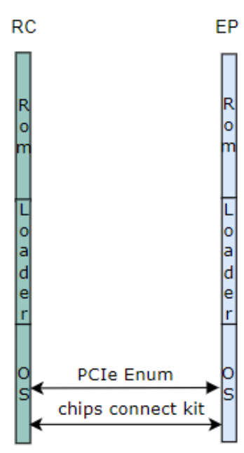
Chinese source flowchart, page 9
2 Hardware configuration
For detailed hardware design, request a reference schematic from RK, for example RK_PCIeEP_DEMO_RK3588_LP4XD200P232SD8_V10_20230323RZF.pdf for RK3588. Adapt the PCIe EP hardware design further to the actual product form factor.
3 DTS configuration
/{
    reserved-memory {
        #address-cells = <2>;
        #size-cells = <2>;
        ranges;
        bar0_region: bar0-region@3c000000 {
            reg = <0x0 0x3c000000 0x0 0x00400000>;
        };
        bar2_region: bar2-region@40000000 {
            reg = <0x0 0x40000000 0x0 0x04000000>; # Bar⼤⼩配置:0x04000000Bytes
        };
    };
}

&pcie3x4 {
        compatible = "rockchip,rk3588-pcie-std-ep";
        memory-region = <&bar0_region>, <&bar2_region>;
        memory-region-names = "bar0", "bar2";
        reset-gpios = <&gpio4 RK_PB6 GPIO_ACTIVE_LOW>; # PERST# GPIO配置
        rockchip,ep-power-independent; # PERST# GPIO配置
        status = "okay";
};
Special settings for independently powered RK chip interconnection (not required for standard cards).
-
reset-gpios = <&gpio3 13 GPIO_ACTIVE_HIGH>; Required: defines the PERST# reset input of the PCIe interface. For both slotted and soldered devices, locate this pin in the schematic and configure it correctly; otherwise stable link establishment may be impossible.
-
wake-gpios = <&gpio3 13 GPIO_ACTIVE_HIGH>; Required: defines the WAKE# output of the PCIe interface. For slotted and soldered devices, locate and configure the pin correctly; otherwise the host cannot be signaled during suspend/resume.
4 Menuconfig configuration
CONFIG_PCIE_DW_ROCKCHIP_EP=y
# CONFIG_STRICT_DEVMEM is not set   #建议开发阶段关闭STRICT_DEVMEM限制,⽅便使⽤io命令调试
5 Device-driver configuration
The PCIe EP (Endpoint) device driver runs on the Root Complex (RC). It controls transfers on the bus and provides the kernel interfaces required by applications. RK RC Kconfig settings follow.
CONFIG_PCIE_FUNC_RKEP=y
General RC-FUNC driver: the RK Chips Connect package supports building a KO module; see chips_connect/patch-kernelx.xx/通用RC-FUNC驱动/.
6 Other software settings
6.1 Software development notes
Some EP-card settings are linked: when changing one, update every related location. For BAR size this includes the PCIe Bin stage (dual-storage scheme) and the SPL stage.
6.2 PCIe Bin-stage configuration
PCIe bin only initializes the PCIe controller in EP mode, before dram.bin initialization. A compiled pcie.bin and source code are provided for customization. The binary is under SDK/rkbin/bin/rkxx/; sources are under patch-*/bootloader. Directly changing pcie.bin settings is recommended; rebuild from source only for special changes.
6.2.1 Dynamic pcie.bin configuration
pcie.bin allows changes to reserved configuration space in the binary for common PCIe settings: PCIe Generation, PCIe lanes, serial baud rate, PCIe vendor id and PCIe device id. Use rkbin/tools/pcie_idb_config.sh; command usage follows.
./tools/pcie_idb_config.sh <soc> <gen> <lanes> <uart_baundary> <vid_l> <vid_h> <did_l> <did_h> <input>
like following:
./tools/pcie_idb_config.sh RK3588 3 4 1500000 87 1d 6a 35 bin/rk35/rk3588_pcie_v*.bin
#vid=0x1d87 did=0x356a
./tools/pcie_idb_config.sh RK3588 3 2 1500000 87 1d 6a 35 bin/rk35/rk3588_pcie_v*.bin
./tools/pcie_idb_config.sh RK3588 3 1 1500000 87 1d 6a 35 bin/rk35/rk3588_pcie_v*.bin
./tools/pcie_idb_config.sh RK3588 3 4 115200  87 1d 6a 35 bin/rk35/rk3568_pcie_v*.bin
./tools/pcie_idb_config.sh RK3568 3 2 1500000 87 1d 6a 35 bin/rk35/rk3588_pcie_v*.bin
If these exposed settings are insufficient, customize the source code.
6.2.2 Building pcie.bin from source
The source depends on tools in rkbin. Extract it beside rkbin/, or change the boot_merger and programmer_image_tool paths in tools/mk_pcie_idb.sh. Determine the compiler toolchain from src/platform/common/GCC/Cortex-A.mk:
#############################################################################
# Cross compiler
#############################################################################
ifneq ($(wildcard ${ROOT_PATH}/../prebuilts/gcc/linux-x86/aarch64/gcc-arm-10.2-2020.11-x86_64-aarch64-none-linux-gnu/bin),)
CROSS_COMPILE   ?= ${ROOT_PATH}/../prebuilts/gcc/linux-x86/aarch64/gcc-arm-10.2-2020.11-x86_64-aarch64-none-linux-bin/aarch64-none-linux-gnu-else ifeq ($(wildcard /opt/prebuilts/gcc/linux-x86/aarch64/arm-gnu-toolchain-11.3.rel1-x86_64-aarch64-none-linux-gnu/bin),)
CROSS_COMPILE   ?= /opt/prebuilts/gcc/linux-x86/aarch64/arm-gnu-toolchain-11.3.rel1-x86_64-aarch64-none-linux-gnu/bin/aarch64-none-linux-gnu-else
CROSS_COMPILE   ?= aarch64-none-linux-gnu-endif
RK3588 build command:
./tools/mk_pcie_idb.sh RK3588
RK3568:
./tools/mk_pcie_idb.sh RK3588
Output file: pcie_idb.img
6.2.2.1 BSP configuration
RK3588 example source: src/platform/RK3588/bsp/platform.h
#define BOOT_USING_UART_BAUD 1500000 // 修改波特率,⽀持1500000或115200
6.2.2.2 Default BAR configuration
Source: src/driver/pcie/pcie_ep.c. The demo defaults below may be customized except BAR4: BAR0: 32bits 4MB, command stream; BAR2: 64bits 64MB, data stream; BAR4: 32bits 1MB, EP PCIe registers, immutable. BAR4 offsets allow direct RC register access: 0: DMA; 0x2000: iATU;
0x20000: MSI-X table
6.2.2.3 BAR size configuration
PCIe_EP_Init() configures BAR sizes using the controller resize BAR feature. For BAR SIZE, (bar_id * 0x8) selects the target BAR ID and bit[13:8] configures the size as 2^n. The source states a range of 1MB (2^0) to 8EB (2^20). BAR0–5 settings follow:
writel(0x2c0, resbar_base + 0x8 + 0 * 0x8);
writel(0x2c0, resbar_base + 0x8 + 1 * 0x8);
writel(0x6c0, resbar_base + 0x8 + 2 * 0x8);
writel(0x6c0, resbar_base + 0x8 + 3 * 0x8);
writel(0x0c0, resbar_base + 0x8 + 4 * 0x8); /* wired register */
writel(0x6c0, resbar_base + 0x8 + 5 * 0x8);
Configure BAR attributes using predefined macros: 32bit or 64bit, with or without PREFETCH.
    rockchip_pcie_ep_set_bar_flag(dbi_base, 0, PCI_BASE_ADDRESS_MEM_TYPE_32);
    rockchip_pcie_ep_set_bar_flag(dbi_base, 2, PCI_BASE_ADDRESS_MEM_PREFETCH |
PCI_BASE_ADDRESS_MEM_TYPE_64);
    rockchip_pcie_ep_set_bar_flag(dbi_base, 4, PCI_BASE_ADDRESS_MEM_TYPE_32);
Disable unused BARs:
//writel(0x0, dbi_base + 0x100000 + 0x10 + 0 * 4);
writel(0x0, dbi_base + 0x100000 + 0x10 + 1 * 4); /* BAR1 disabled */
//writel(0x0, dbi_base + 0x100000 + 0x10 + 2 * 4);
//writel(0x0, dbi_base + 0x100000 + 0x10 + 3 * 4);
//writel(0x0, dbi_base + 0x100000 + 0x10 + 4 * 4);
writel(0x0, dbi_base + 0x100000 + 0x10 + 5 * 4);  /* BAR5 disabled */
PCIe Bin BAR size is a linked setting. Update PCIe Bin (dual storage), SPL and Kernel BAR-size settings together.
6.2.2.4 BAR mapping configuration
RK3588 example source: src/platform/RK3588/bsp/platform.h
#define BOOT_USING_PCIE_EP_BAR0_CPU_ADDRESS 0x3C000000 // 调整Bar0映射地址
Code implementation:
HAL_PCIE_InboundConfig(pcie, 0, 0, BOOT_USING_PCIE_EP_BAR0_CPU_ADDRESS);
PCIe.bin-stage BAR mapping is independent of Kernel-stage mapping; different regions may be mapped as needed.
6.2.2.5 PHY mode configuration
RK3588 combines phy0/1 by default for Gen3x4. It supports splitting into Gen3x2, Gen3x2, Gen3x1 as stated in the source. RK3588 PCIe PHY 3x2 example:
diff --git a/src/hal/lib/bsp/RK3588/hal_bsp.c b/src/hal/lib/bsp/RK3588/hal_bsp.c
index 4a6c2e6..f03995b 100644
--- a/src/hal/lib/bsp/RK3588/hal_bsp.c
+++ b/src/hal/lib/bsp/RK3588/hal_bsp.c
@@ -123,7 +123,7 @@ const struct HAL_UART_DEV g_uart9Dev =
 #ifdef HAL_PCIE_MODULE_ENABLED
 const struct HAL_PHY_SNPS_PCIE3_DEV g_phy_pcie3Dev =
 {
-    .phyMode = PHY_MODE_PCIE_AGGREGATION,
+    .phyMode = PHY_MODE_PCIE_NANBNB,
 };

 struct HAL_PCIE_DEV g_pcieDev =
RK3588 PCIe PHY 3x1 example:
diff --git a/src/hal/lib/bsp/RK3588/hal_bsp.c b/src/hal/lib/bsp/RK3588/hal_bsp.c
index 4a6c2e6..f03995b 100644
--- a/src/hal/lib/bsp/RK3588/hal_bsp.c
+++ b/src/hal/lib/bsp/RK3588/hal_bsp.c
@@ -123,7 +123,7 @@ const struct HAL_UART_DEV g_uart9Dev =
 #ifdef HAL_PCIE_MODULE_ENABLED
 const struct HAL_PHY_SNPS_PCIE3_DEV g_phy_pcie3Dev =
 {
-    .phyMode = PHY_MODE_PCIE_AGGREGATION,
+    .phyMode = PHY_MODE_PCIE_NABIBI,
 };

 struct HAL_PCIE_DEV g_pcieDev =
6.2.3 PCIe Bin packaging and programming
6.2.3.1 Programming with software tools
- Convert pcie.bin to pcie_idb.img.
#⽣成 loader
./tools/boot_merger RKBOOT/RK3588MINIALL_PCIE_EP.ini
$git:(master) $ ls rk3588_pcie_loader_v1.00.bin
rk3588_pcie_loader_v1.00.bin

#spinand 制作 idb,要求使⽤ spinand type 做对⻬
./tools/programmer_image_tool -i rk3588_pcie_loader_v1.00.bin -b 128 -p 2 -t spinand -o ./
#emmc
./tools/programmer_image_tool -i rk3588_pcie_loader_v1.00.bin -t emmc -o ./

#制作双备份的 pcie_idb.img
cat idblock.img > pcie_idb.img
cat idblock.img >> pcie_idb.img
rm idblock.img
-
For separate-image programming, add a pcie_idb partition: eMMC flash start address 0x40; SPI flash start address 0x100. Enable CLOSE_CHECK_IDB=TRUE in the programming tool config.ini. Enter Maskrom mode and click the programming button.
-
For a complete package, add pcie_idb to the partition table. The example is eMMC; SPI NAND uses a different address.
CMDLINE:
mtdparts=rk29xxnand:0x00000400@0x00000040(pcie_idb),0x00000800@0x00002000(security),0x00002000@0x00004000(uboot),0x00010000@0x00006000(boot),0x00064000@0x00016000(rootfs),-@0x0007a000(userdata:grow)
Modify package-file: tools/linux/Linux_Pack_Firmware/rockdev/rk3588-package-file-nvr-emmc / spi-nand.
package-file    package-file
bootloader      Image/MiniLoaderAll.bin
pcie_idb        Image/pcie_idb.img    #添加pcie_idb⽂件
parameter       Image/parameter.txt
uboot           Image/uboot.img
boot            Image/boot.img
rootfs          Image/rootfs.img
userdata        Image/userdata.img
Run build_emmc.sh to build update.img and program it.
6.2.3.2 Programming with a programmer
Refer to EP-card firmware programming.
6.3 SPL-stage configuration
6.3.1 Kconfig configuration
This SPL feature has the three Kconfig entries below. Products requiring EP Boot must select all three; products without EP Boot only need SPL_PCIE_EP_SUPPOR, as spelled in the source.
CONFIG_SPL_PCIE_EP_SUPPORT=y
CONFIG_SPL_RAM_SUPPORT=y
CONFIG_SPL_RAM_DEVICE=y
6.3.2 Default BAR configuration
Demo defaults, customizable except BAR4: BAR0: 32bits 4MB, command stream; BAR2: 64bits 64MB, data stream; BAR4: 32bits 1MB, EP PCIe registers, immutable. BAR4 offsets accessible directly from RC: 0: DMA; 0x2000: iATU; 0x20000: MSI-X table.
6.3.3 BAR size configuration
pcie_bar_init() sets BAR size using resize BAR. The offset+0x8 register bit[13:8] sets size as 2^n; the source specifies 1MB (2^0) to 8EB (2^20):
/* Resize BAR0 to support 4M 32bits */
resbar_base = dbi_base + 0x2e8;
writel(0xfffff0, resbar_base + 0x4);
writel(0x2c0, resbar_base + 0x8);
/* BAR2: 64M 64bits */
writel(0xfffff0, resbar_base + 0x14);
writel(0x6c0, resbar_base + 0x18);
/* BAR4: Fixed for EP wired register, 2M 32bits */
writel(0xfffff0, resbar_base + 0x24);
writel(0xc0, resbar_base + 0x28);
Configure BAR attributes with predefined macros: 32bit/64bit and PREFETCH.
        rockchip_pcie_ep_set_bar_flag(dbi_base, 0, PCI_BASE_ADDRESS_MEM_TYPE_32);
        rockchip_pcie_ep_set_bar_flag(dbi_base, 2, PCI_BASE_ADDRESS_MEM_PREFETCH |
PCI_BASE_ADDRESS_MEM_TYPE_64);
        rockchip_pcie_ep_set_bar_flag(dbi_base, 4, PCI_BASE_ADDRESS_MEM_TYPE_32);
Disable unused BARs:
/* Close bar1 bar3 bar5 */
writel(0x0, dbi_base + 0x100000 + 0x14);
//writel(0x0, dbi_base + 0x100000 + 0x18);
writel(0x0, dbi_base + 0x100000 + 0x1c);
//writel(0x0, dbi_base + 0x100000 + 0x20);
writel(0x0, dbi_base + 0x100000 + 0x24);
/* Close ROM BAR */
writel(0x0, dbi_base + 0x100000 + 0x30);
SPL BAR size is linked to PCIe Bin (dual storage), SPL and Kernel BAR-size settings; update all together.
6.3.4 BAR mapping configuration
pcie_inbound_config() maps each BAR to an internal memory region. Change RKEP_BAR0_ADDR and RKEP_BAR2_ADDR to change the target addresses.
/* BAR0: RKEP_BAR0_ADDR */
writel(RKEP_BAR0_ADDR, base + PCIE_ATU_CPU_ADDR_LOW);
writel(0, base + PCIE_ATU_CPU_ADDR_HIGH);
writel(0, base + PCIE_ATU_UNR_REGION_CTRL1);
/* PCIE_ATU_UNR_REGION_CTRL2 */
writel(PCIE_ATU_ENABLE | PCIE_ATU_BAR_MODE_ENABLE | (0 << 8),
       base + PCIE_ATU_UNR_REGION_CTRL2);
SPL BAR mapping is independent of Kernel mapping; different regions may be mapped.
6.3.5 PHY mode configuration
The demo uses controller 0xfe150000 in PCIe3x4 mode, so the PHY also has four lanes. Because the PHY can be split, change pcie_cru_init() for another mode. For 2lane+2lane, change PHY_MODE_PCIE_AGGREGATION to PHY_MODE_PCIE_NANBNB or another appropriate value:
RK3588 PCIe PHY 3x2 example:
diff --git a/arch/arm/mach-rockchip/spl_pcie_ep_boot.c b/arch/arm/mach-rockchip/spl_pcie_ep_boot.c
index 8b054d91558..54f9d22cde2 100644
--- a/arch/arm/mach-rockchip/spl_pcie_ep_boot.c
+++ b/arch/arm/mach-rockchip/spl_pcie_ep_boot.c
@@ -384,7 +384,7 @@ static void pcie_board_init(void)
 #define PHY_MODE_PCIE_NABINB   2       /* P1:PCIe3x1*2 + P0:PCIe3x2 */
 #define PHY_MODE_PCIE_NABIBI   3       /* P1:PCIe3x1*2 + P0:PCIe3x1*2 */

-#define PHY_MODE_PCIE                  PHY_MODE_PCIE_AGGREGATION
+#define PHY_MODE_PCIE                  PHY_MODE_PCIE_NANBNB

 #define CRU_BASE_ADDR                  0xfd7c0000
 #define CRU_SOFTRST_CON32              (CRU_BASE_ADDR + 0x0a80)
RK3588 PCIe PHY 3x1 example:
diff --git a/arch/arm/mach-rockchip/spl_pcie_ep_boot.c b/arch/arm/mach-rockchip/spl_pcie_ep_boot.c
index 8b054d91558..54f9d22cde2 100644
--- a/arch/arm/mach-rockchip/spl_pcie_ep_boot.c
+++ b/arch/arm/mach-rockchip/spl_pcie_ep_boot.c
@@ -384,7 +384,7 @@ static void pcie_board_init(void)
 #define PHY_MODE_PCIE_NABINB   2       /* P1:PCIe3x1*2 + P0:PCIe3x2 */
 #define PHY_MODE_PCIE_NABIBI   3       /* P1:PCIe3x1*2 + P0:PCIe3x1*2 */

-#define PHY_MODE_PCIE                  PHY_MODE_PCIE_AGGREGATION
+#define PHY_MODE_PCIE                  PHY_MODE_PCIE_NABIBI

 #define CRU_BASE_ADDR                  0xfd7c0000
 #define CRU_SOFTRST_CON32              (CRU_BASE_ADDR + 0x0a80)
6.3.6 EP Boot configuration
EP waits for firmware and executes it, requiring agreement with RC on the download protocol and between BootLoader stages on firmware locations. Downloads use pcie_wait_for_fw(); later-stage locations use pcie_update_atags(). Modify the addresses below only when RC/EP commands and addresses and inter-stage firmware locations remain consistent. Do not modify them without understanding the whole flow. RC first downloads firmware to the specified locations, then sends the execute command.
- Agreed download locations for two firmware images:
| Firmware | Format | Contents | Download address |
|---|---|---|---|
| uboot.img | FIT | ATF and U-Boot | BAR2+0 |
| boot.img | FIT | Kernel, DTB, ramdisk | BAR2+0x400000 |
- Firmware execution command:
| Command | Location | Value | Action |
|---|---|---|---|
| CMD_LOADER_RUN | BAR0 + 0x400 | 0x524b4501 | Run downloaded firmware |
Of the two RC-downloaded images, SPL (the EP Boot environment) directly parses and runs uboot.img. An RK-specific RAM_PARTITION passes the boot.img location to U-Boot. pcie_update_atags() defines the boot partition RAM start and SIZE. Default BAR2 is 64M: the first 4M is for uboot.img, the remaining 60M for boot.img, allowing the RC CPU to write through BAR2 directly. If this is insufficient, RC can invoke EP DMA to download without the BAR2 size limit; update RAM_PARTITION size consistently.
6.3.7 SRNS configuration
For designs supporting SRNS reference clocks, enable the following macro. EP then uses its internal 100MHz reference clock without relying on an external clock.
/* SRNS: Use Seperate refclk(internal clock) instead of from RC */
// #define PCIE_ENABLE_SRNS_PLL_REFCLK
SPL SRNS settings are linked: update PCIe Bin SRNS (dual storage), SPL SRNS-size settings (source wording) and Kernel SRNS together.
6.4 Kernel-stage configuration
6.4.1 BAR size configuration
rockchip_pcie_resize_bar sets BAR sizes through resize BAR. In register offset+0x8, bit[13:8] selects size as 2^n; the source states 1MB (2^0) to 8EB (2^20). Use predefined macros for 32bit/64bit and PREFETCH attributes:
/* Resize BAR0 4M 32bits, BAR2 64M 64bits-pref, BAR4 1MB 32bits */
bar = BAR_0;
dw_pcie_writel_dbi(pci, resbar_base + 0x4 + bar * 0x8, 0xfffff0);
dw_pcie_writel_dbi(pci, resbar_base + 0x8 + bar * 0x8, 0x2c0);
rockchip_pcie_ep_set_bar_flag(rockchip, bar, PCI_BASE_ADDRESS_MEM_TYPE_32);

bar = BAR_2;
dw_pcie_writel_dbi(pci, resbar_base + 0x4 + bar * 0x8, 0xfffff0);
dw_pcie_writel_dbi(pci, resbar_base + 0x8 + bar * 0x8, 0x6c0);
rockchip_pcie_ep_set_bar_flag(rockchip, bar,PCI_BASE_ADDRESS_MEM_PREFETCH |
PCI_BASE_ADDRESS_MEM_TYPE_64);

bar = BAR_4;
dw_pcie_writel_dbi(pci, resbar_base + 0x4 + bar * 0x8, 0xfffff0);
dw_pcie_writel_dbi(pci, resbar_base + 0x8 + bar * 0x8, 0xc0);
rockchip_pcie_ep_set_bar_flag(rockchip, bar, PCI_BASE_ADDRESS_MEM_TYPE_32);
Disable unused BARs:
/* Disable BAR1 BAR5*/
bar = BAR_1;
dw_pcie_writel_dbi(pci, PCIE_TYPE0_HDR_DBI2_OFFSET + 0x10 + bar * 4, 0);
bar = BAR_5;
dw_pcie_writel_dbi(pci, PCIE_TYPE0_HDR_DBI2_OFFSET + 0x10 + bar * 4, 0);
Kernel BAR size is linked: update PCIe Bin (dual storage), SPL and Kernel BAR sizes together. Kernel BAR mapping is independent of SPL and may map different regions.
6.4.2 BAR mapping configuration
Each BAR is mapped to an internal memory region; change the DTS to change target addresses.
reserved-memory {
       #address-cells = <2>;
       #size-cells = <2>;
       ranges;
       bar0_region: bar0-region@3c000000 {
                reg = <0x0 0x3c000000 0x0 0x00400000>;
       };
       bar2_region: bar2-region@40000000 {
                reg = <0x0 0x40000000 0x0 0x04000000>;
       };
};
Additional bar1/bar5 memory mappings are supported and automatically enable bar1/5. If PCIe Bin/SPL initializes PCIe, comment out the bar1/5 disabling code as described under BAR size configuration.
6.4.3 SRNS configuration
SRNS support is supplied as a patch: obtain 0001-TEST-kernel5.10-rk3588-SRNS.patch from the development package. Kernel SRNS settings are linked to PCIe Bin SRNS (dual storage) and SPL SRNS-size settings (source wording); update them together.
6.5 Building EP-card firmware
Apply the appropriate patches according to the patch directory, then choose the scenario. Flash Boot with PCIe Bin, single storage: add pcie_idb and update pcie_idb.img; add normal_idb and update normal_idb.img automatically through MiniLoaderAll.bin; build the other partition images and update.img normally. Dual storage: follow the RK PCIe EP dual-storage chapter of Rockchip_Developer_Guide_Dual_Storage_CN.pdf. The SDK does not package dual-storage firmware into update.img by default. Use tools/dual_storage, copy partition images as described in tools/dual_storage/README.txt, and run build.sh. Flash Boot with PCIe Bin and EP Boot, general PC: add pcie_idb/pcie_idb.img and normal_idb/normal_idb.img (the latter automatically through MiniLoaderAll.bin); the host supplies remaining firmware. For RK RC, PCIe Bin integration may be omitted; SPL alone implements EP Boot, EP storage holds only Miniloader, and the host supplies the rest. Common Boot: build partition images and update.img normally without special settings.
6.6 Programming EP-card firmware
Single storage: firmware programming is identical to normal firmware; follow the flashing chapter of the chip release documentation. Dual storage: see “RK PCIe EP dual-storage firmware packaging” in Rockchip_Developer_Guide_Dual_Storage_CN.pdf.
6.7 EP-card OTA
Partition updates use the partition table to create kernel device nodes; userspace writes nodes under /dev/ to update partitions. Use RK recovery-mode OTA or a custom solution that writes these device nodes.
-
Flash Boot with PCIe Bin OTA. Single storage: normal OTA, following docs\Linux\Recovery\Rockchip_Developer_Guide_Linux_Recovery_CN.pdf. Dual storage: see “RK PCIe EP dual-storage OTA upgrade” in Rockchip_Developer_Guide_Dual_Storage_CN.pdf.
-
OTA for Flash Boot integrating PCIe Bin and EP Boot. EP Boot has only a loader partition, which must be added to the partition table. NOR: refer to EP-card OTA > dual storage > NOR Uboot partition configuration. EMMC: refer to the EMMC dual-storage section and add loader directly to the partition table. RK OTA cannot update loader alone; implement it separately. Updating loader is not recommended because of the high risk. MiniLoaderAll.bin and parameter.txt cannot be written directly to /dev/ nodes; convert them to binary files first.
7 Troubleshooting
7.1 EP-card boot troubleshooting
EP-card SPL-stage output:
U-Boot SPL board init
RKEP: Init PCIe EP
RKEP: 175301 - PHY Mode 0x4
RKEP: 176542 - RefClock in common clock_mode
RKEP: 187578 - BAR0: 0x3c000000
RKEP: 187848 - BAR2: 0x010000000
RKEP: 188227 - init PCIe fast Link up
RKEP: 208576 - Link up 230011
RKEP: 243683 - Done
If execution stops at “RKEP: Init PCIe EP”, enumeration usually failed. Check the EP reference clock, 12V power and release of PERST#. EP-card Kernel-stage output follows.
[root@RK3588:/]# dmesg | grep pci
[    3.371073] rk-pcie-ep fe150000.pcie: bar0: assigned [0x3c000000-3c3fffff]
[    3.371890] rk-pcie-ep fe150000.pcie: bar2: assigned [0x40000000-43ffffff]
[    3.371901] rk-pcie-ep fe150000.pcie: no vpcie3v3 regulator found
[    3.371918] rk-pcie-ep fe150000.pcie: already linkup
[    3.372001] rk-pcie-ep fe150000.pcie: register misc device pcie_ep
[    3.725930] ehci-pci: EHCI PCI platform driver
[    3.869983] pcie30_avdd1v8: supplied by avcc_1v8_s0
[    3.870541] pcie30_avdd0v75: supplied by avdd_0v75_s0
EP device-driver kernel-module output:
rk3588_s:/ # dmesg | grep rkep
[    2.278964] pcie-rkep 0000:01:00.0: success to request msi irq
    # 成功申请MSI 中断 log
[    2.280601] pcie-rkep 0000:01:00.0: successfully allocate continuouse buffer for
userspace   # 成功预留⽤⼾内存,默认不开
[    2.280619] pcie-rkep 0000:01:00.0: vid=1d87
    # 正常访问EP卡config空间
[    2.280625] pcie-rkep 0000:01:00.0: did=356a
[    2.280629] pcie-rkep 0000:01:00.0: obj_info magic=524b4550, ver=100
    # 正常访问EP卡bar空间
7.2 Fault handling
System instability and external interference can cause faults in products. PCIe includes interference protection, CRC at protocol layers and retransmission on errors; the source describes these as ensuring correct controller output. Faults that the PCIe controller cannot recover from require additional measures to maintain device operation.
7.2.1 EP health status
Run a small EP program representing device health, updated simply by ticks. RC reads it to determine whether EP is operating normally. The demo reserves BAR0 space for health-state updates and queries.
7.2.2 Watchdog
RK3588 has a watchdog for automatic reset on system faults. Feeding it from the health-status program allows reset when that program stops. The source wording says the EP PCIe module is abnormal and other module faults hang the system; this diagnostic wording needs checking. RC software does not know about an EP-initiated reset. The PCIe physical layer reconnects afterward, but EP must restore RC-programmed registers such as BAR addresses before communication can resume.
7.2.3 Hot Reset
The source calls this signal Host Reset in the text under Hot Reset. It is defined by PCIe and travels over normal data lanes. The EP controller detects it and interrupts. Hardware automatically responds to HotReset by resetting BAR-related registers, so the interrupt handler must initialize EP again to restore correct BAR and ATU settings.
7.2.4 Warm Reset (PERST)
PERST independently resets the PCIe module. Observations show x86 restart asserts PERST without cycling PCIe-slot power. EP must therefore reset completely on PERST. The RK recommendation is direct connection to RK3588 and PMIC NPOR to achieve a power-on-reset equivalent. Where RC is controllable and this requirement is weaker, PERST can be an interrupt GPIO whose handler triggers RK3588 global reset in software.
7.2.5 Cold Reset (Power On Reset)
Power-on reset corresponds to the device startup sequence.
7.2.6 Reset and suspend/resume with independently powered RK chip interconnection
Hardware/software requirements: RC needs a WAKE# GPIO in the PMU IO domain with GPIO wakeup implemented independently of PCIe. Increase rockchip,wait-for-link-ms to cover the EP power-up timing, based on actual EP boot time; see Rockchip_Developer_Guide_PCIe_CN.pdf. EP must implement WAKE# and PERST# GPIOs as described in the independently powered RK-interconnection special settings under Kernel-stage configuration.
Provide an EP reset-control signal for exceptional hardware recovery and enable Watchdog for software recovery. This reference design needs dedicated stress testing because of its customized hardware/software flows; adapt it to project experience and requirements. Reset flows: when RC resets while EP stays powered, RC userspace notifies EP, deinitializes services (see software-message notification), resets RC and reinitializes services. When EP resets while RC remains powered, RC userspace notifies EP, deinitializes services, resets EP and reinitializes, including RC PCIe rescan. Suspend/resume: with EP powered, RC notifies EP, deinitializes services, suspends/resumes and reinitializes including rescan. With RC powered, EP notifies RC, deinitializes services, suspends/resumes and reinitializes including RC rescan. For both, use an ordered sequence such as RC suspend → EP suspend → EP resume → RC resume. EP notifies RC to suspend and uses WAKE# to wake RC.