
Rockchip platform reference, source V6.29.0. Verify the actual ArmSoM board SoC, PCIe wiring/PHY, SDK/BSP, kernel, peripheral and power design; this does not certify universal board support. Examples, registers and patches are source material, not ArmSoM hardware validation. Chinese uses Chinese figures; other languages use English figures.
Source chip and kernel coverage
| Chip | Kernel version |
|---|---|
| RK1808 | 4.4, 4.19 |
| RK3528 | 4.19, 5.10, 6.1 |
| RK3562 | 5.10, 6.1 |
| RK3566/RK3568 | 4.19, 5.10, 6.1 |
| RK3576 | 6.1 |
| RK3588 | 5.4, 5.10, 6.1 |
RK3399 uses a different PCIe controller IP and is outside this guide; refer to Rockchip_RK3399_Developer_Guide_PCIe_CN.
1. Chip Resource Introduction
For the address ranges of BAR (Base Address Register) spaces that can be allocated by each controller within the chip, please refer to the Internal Address Mapping section under the PCIe chapter in the respective chip’s TRM (Technical Reference Manual). The keyword to look for is PCIe Outbound Memory . Each controller’s corresponding table includes the starting address (Base Address) and total size (Address Length) for both 32- bit BARs and 64-bit BARs. Note: The peripheral configuration space, I/O space, and memory (MEM) space share this address segment, and the MEM space does not support prefetching.
1.1 RK1808
| Resource | Mode | Lane Splitting | DMA | IOMMU | ASPM | Remarks | MSI |
|---|---|---|---|---|---|---|---|
| PCIe Gen2 x 2 lane | RC/EP | No | 2 read Channels + 2 write Channels | No | L0s/L1 | Internal Clock | 65535 |
1.2 RK3528
| Resource | Mode | Lane Splitting | DMA | IOMMU | ASPM | Remarks | MSI |
|---|---|---|---|---|---|---|---|
| PCIe Gen2 x 1 lane | RC only | No | No | No | ALL | Internal Clock | 32 |
1.3 RK3562
| Resource | Mode | Lane Splitting | DMA | IOMMU | ASPM | Remarks | MSI |
|---|---|---|---|---|---|---|---|
| PCIe Gen2 x 1 lane | RC only | No | No | No | ALL | Internal Clock | 32 |
1.4 RK3566
| Resource | Mode | Lane Splitting | DMA | IOMMU | ASPM | Remarks | MSI |
|---|---|---|---|---|---|---|---|
| PCIe Gen2 x 1 lane | RC only | No | No | No | L0s/L1 | Internal Clock | 65535 |
1.5 RK3568
1.5.1 Controller
| Resource | Mode | Lane Splitting | DMA | IOMMU | ASPM | Remarks | MSI |
|---|---|---|---|---|---|---|---|
| PCIe Gen2 x 1 lane | RC only | No | No | No | L0s/L1 | Internal Clock | 65535 |
| PCIe Gen3 x 2 lane | RC/EP | 1 lane RC + 1 lane RC | 2 Read Channels + 2 Write Channels | No | ALL | External Oscillator, Only Supports pcie30phy | 65535 |
| PCIe Gen3 x 1 lane | RC | 1 lane RC | No | No | ALL | External Oscillator, Only Supports pcie30phy | 65535 |
1.5.2 PHY
| Resource | DTS Node | Reference Clock | Splitting | Combo Capability |
|---|---|---|---|---|
| pcie30phy | phy@fe8c0000 | External | 2Lane: Default 1Lane + 1Lane: rockchip, bifurcation | PCIe Exclusive |
| combphy2_psq | phy@fe840000 | Internal/External | - | Combo with SATA/RGMII |
Explanation: pcie30phy 2Lane default configuration is PCIe Gen3 x 2 lane, after splitting, “PCIe Gen3 x 2 lane” and “PCIe Gen3 x 1 lane” controllers each have 1Lane. pcie30phy supports the separate refclk architecture of SRNS No SSC, configuration reference to the
appendix “RK3568 pcie30phy SRNS Patch” section, it is recommended to ensure signal consistency through standard signal measurement kits and peripheral stress testing.
1.6 RK3576
| Resource | Mode | Lane Splitting Supported | DMA Supported | IOMMU Supported | ASPM Supported | Remarks | MSI |
|---|---|---|---|---|---|---|---|
| PCIe Gen2 x 1 lane | RC only | No | No | Yes | ALL | Internal Clock | 32 |
| PCIe Gen2 x 1 lane | RC only | No | No | Yes | ALL | Internal Clock | 32 |
1.7 RK3588
The RK3588 features five PCIe controllers, which share the same hardware IP but have different configurations. One of the 4-lane DM mode controllers can be used as an Endpoint (EP), while the other 2-lane and three 1-lane controllers can only function as Root Complexes (RC). The RK3588 is equipped with two types of PCIe PHYs. One type is the PCIe 3.0 PHY, which includes two Ports with a total of four Lanes. The other type is the PCIe 2.0 PHY, which consists of three units, each with a single Lane, and they are used in conjunction with SATA and USB. The 4-lane PCIe 3.0 PHY can be split according to actual requirements. After splitting, the corresponding controllers need to be properly configured, and all configurations are completed in the Device Tree Source (DTS) without the need to modify the driver. Usage limitations:
- After splitting the PCIe 3.0 PHY, the PCIe 3.0 x4 controller can only be fixedly paired with the port0 of the PCIe 3.0 PHY when operating in 2-lane mode, and can only be fixedly paired with port0 lane0 when operating in 1-lane mode;
- After splitting the PCIe 3.0 PHY, the PCIe 3.0 x2 controller can only be fixedly paired with the port1 of the PCIe 3.0 PHY when operating in 2-lane mode, and can only be fixedly paired with port1 lane0 when operating in 1-lane mode;
- When the PCIe 3.0 PHY is split into four 1-lane units, the port0 lane1 of the PCIe 3 PHY can only be fixedly paired with the PCIe 2 x1 l0 controller, and the port1 lane1 can only be fixedly paired with the PCIe 2 x1 l1 controller;
- The PCIe 3.0 x4 controller operating in EP mode can use the 4-lane mode or the 2-lane mode with the port0 of the PCIe 3.0 PHY, and the two lanes of port1 of the PCIe 3.0 PHY can be used as RC to cooperate with other controllers. By default, when using a common clock as the reference clock, it is not possible for the lane0 of the PCIe 3.0 PHY port0 to operate in EP mode while lane1 operates in RC mode to cooperate with other controllers, because the two lanes of Port0 share a common input reference clock, and the simultaneous use of the clock by RC and EP may cause conflicts.
- If only one port of the RK3588 PCIe 3.0 PHY is used, the other port still needs to be powered, and other signals such as refclk can be grounded.
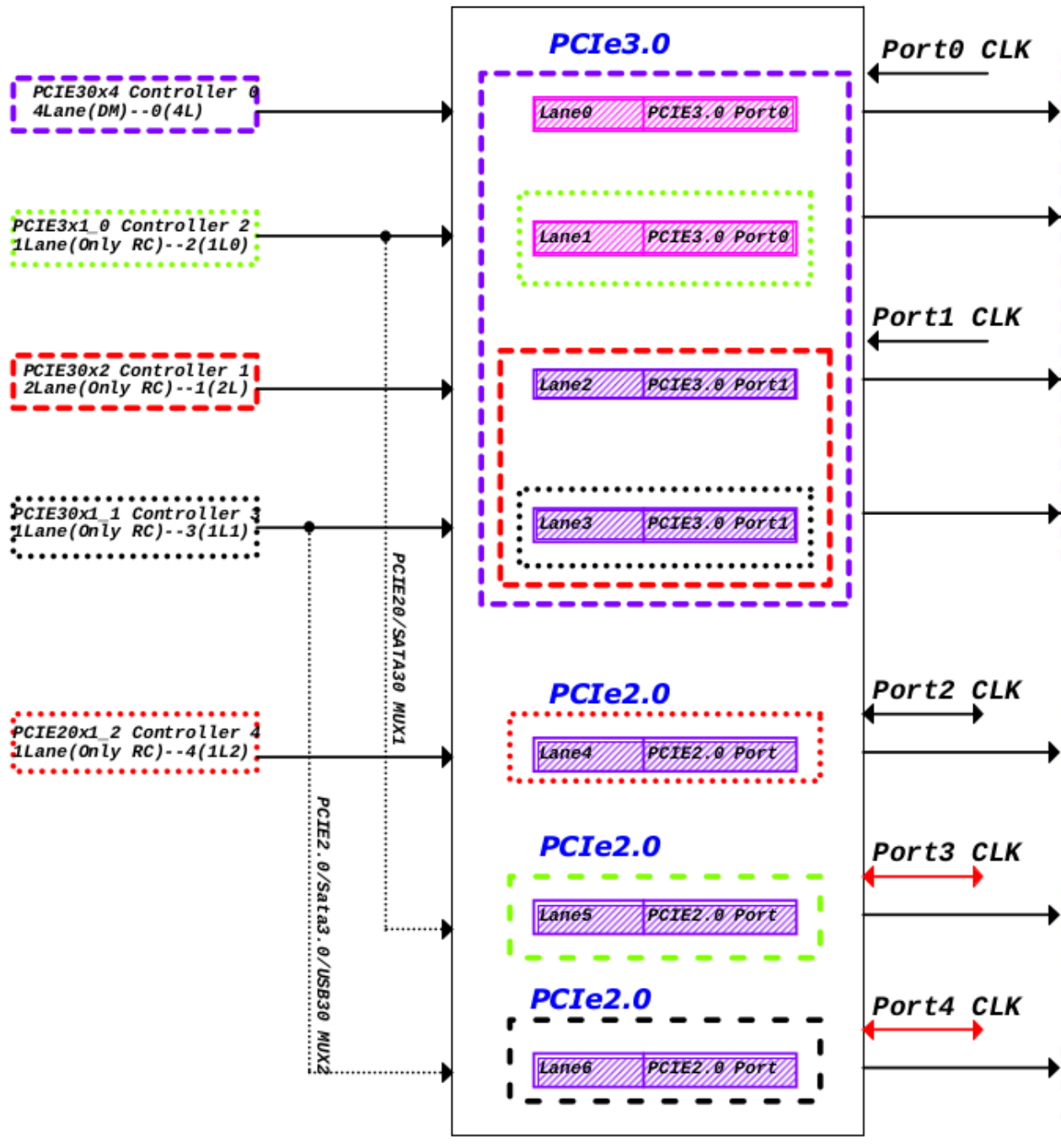
Original English figure — 14
1.7.1 Controller
| Resource | Mode | DTS Node | Available PHY | Internal DMA | Supported ASPM | Supported IOMMU | MSI |
|---|---|---|---|---|---|---|---|
| PCIe Gen3 x 4 lane | RC/EP | pcie3x4: pcie@fe150000 | pcie30phy | 2 read Channels + 2 write Channels | ALL | Yes | 63353 |
| PCIe Gen3 x 2 lane | RC only | pcie3x2: pcie@fe160000 | pcie30phy | No | ALL | Yes | 63353 |
| PCIe Gen3 x 1 lane | RC only | pcie2x1l0: pcie@fe170000 | pcie30phy, combphy1_ps | No | ALL | Yes | 63353 |
| PCIe Gen3 x 1 lane | RC only | pcie2x1l1: pcie@fe180000 | pcie30phy, combphy2_psu | No | ALL | Yes | 63353 |
| PCIe Gen3 x 1 lane | RC only | pcie2x1l2: pcie@fe190000 | combphy0_ps | No | ALL | Yes | 63353 |
1.7.2 PHY
| Resource | DTS Node | Reference Clock | Splitting | Combo Support |
|---|---|---|---|---|
| pcie30phy | phy@fee80000 | External | 4Lane1: PHY_MODE_PCIE_AGGREGATION 2Lane+2Lane: PHY_MODE_PCIE_NANBNB 2Lane+1Lane+1Lane: PHY_MODE_PCIE_NANBBI 1Lane4: PHY_MODE_PCIE_NABIBI | PCIe Specific |
| combphy0_ps | phy@fee00000 | Internal/External | - | Combined with SATA |
| combphy1_ps | phy@fee10000 | Internal/External | - | Combined with SATA |
| combphy2_psu | phy@fee20000 | Internal/External | - | Combined with SATA/USB3 |
Explanation: pcie30phy does not support separate refclk architecture.
1.8 RK3588S
The PCIe interface of RK3588S is relatively straightforward, featuring 2 single-lane controllers and 2 single- lane comboPHYs that can be utilized for PCIe 2.0, with a one-to-one correspondence relationship.
1.8.1 Controller
| Resource | Mode | DTS Node | Available PHY | Internal DMA | ASPM | IOMMU | MSI |
|---|---|---|---|---|---|---|---|
| PCIe Gen3 x 1 lane | RC only | pcie2x1l1: pcie@fe180000 | combphy2_psu | No | ALL | Yes | 65535 |
| PCIe Gen3 x 1 lane | RC only | pcie2x1l2: pcie@fe190000 | combphy0_ps | No | ALL | Yes | 65535 |
1.8.2 PHY
| Resource | DTS Node | Reference Clock | Split | Combo with SATA/USB3 |
|---|---|---|---|---|
| combphy0_ps | phy@fee00000 | Internal/External | - | Combined with SATA |
| combphy2_psu | phy@fee20000 | Internal/External | - | Combined with SATA/USB3 |
2. DTS Configuration
2.1 Configuration Key Points
The configuration of PCIe is mostly fixed, and there are not many variables that need to be configured at the board level DTS. Refer to the following key points for configuration:
- Controller/PHY Enable: After determining the scheme, enable the correct controller and PHY according to the schematic diagram. Note that the index of the controller and PHY may not be sequentially matched, such as RK3588’s PCIe2x1l0 does not correspond to combphy0_ps;
- Controller: Some controllers (such as RK3588’s PCIe2x1l0 and PCIe2x1l1) have more than one PHY option, configure the “phys” correctly according to the scheme design;
- Controller: As RC, it is usually necessary to configure “reset-gpios”, which corresponds to the “PERSTn” signal of PCIE in the schematic diagram;
- Controller: As RC, it may be necessary to configure “vpcie3v3-supply”, which corresponds to the fixed regulator controlled by the “PWREN” gpio signal of PCIE;
- Controller: When used as EP, it is necessary to modify “compatible” to the corresponding string for EP mode;
- PHY: The PCIe30phy has a total of 4 lanes, which can be used separately, and it is necessary to correctly configure the “rockchip,pcie30-phymode” mode according to the scheme.
2.2 RK1808 DTS Configuration
The DTS configuration for RK1808, all implementation modes have examples in the SDK’s evb code that can be referenced. You can copy the matching content according to the patterns in the table below to the product board-level dts for use.
| Resource | Mode | Reference Configuration | Controller Node | PHY Node | Remarks |
|---|---|---|---|---|---|
| PCIe Gen2 x 2 lane | RC | rk1808-evb.dtsi | pcie0@fc400000 | combphy | Need to disable usbdrd_dwc3 and usbdrd3 |
| PCIe Gen2 x 2 lane | EP | Add compatible = “rockchip,rk1808-pcie-ep”, “snps,dw-pcie” to the pcie0 node in rk1808-evb.dtsi; | pcie0@fc400000 | combphy | Need to disable usbdrd_dwc3 and usbdrd3 |
2.3 RK3528 DTS Configuration
The DTS configuration for RK3528, all implementation modes have examples in the SDK’s evb code for reference, and you can copy the matching content according to the modes listed in the table below to use in the product board-level dts.
| Resource | Mode | Reference Configuration | Controller Node | PHY Node | Note |
|---|---|---|---|---|---|
| PCIe Gen2 x 1 lane | RC | rk3528-evb2-ddr3-v10.dtsi | pcie2x1@fe4f0000 | combphy_pu | - |
2.4 RK356X DTS Configuration
The DTS configuration for RK356x, all implementation modes have examples in the SDK’s evb code for reference, you can select the matching content according to the pattern in the table below and copy it to the product board-level DTS for use.
2.4.1 RK3562 dts
| Resource | Mode | Reference Configuration | Controller Node | PHY Node |
|---|---|---|---|---|
| PCIe Gen2 x 1 lane | RC | rk3562-evb1-lp4x-v10.dtsi | pcie2x1@ff500000 | combphy_pu |
2.4.2 RK3566 dts
| Resource | Mode | Reference Configuration | Controller Node | PHY Node |
|---|---|---|---|---|
| PCIe Gen2 x 1 lane | RC | rk3566-evb1-ddr4-v10.dtsi | pcie2x1@fe260000 | combphy2_psq |
2.4.3 RK3568 dts
| Resource | Mode | Reference Configuration | Controller Node | PHY Node |
|---|---|---|---|---|
| PCIe Gen2 x 1 lane | RC | rk3568-evb2-lp4x-v10.dtsi | pcie2x1@fe260000 | combphy2_psq |
| PCIe Gen3 x 2 lane | RC | rk3568-evb1-ddr4-v10.dtsi | pcie3x2@fe280000 | pcie30phy |
| PCIe Gen3 Split 1 lane + 1 lane | RC | rk3568-evb6-ddr3-v10.dtsi | pcie3x2@fe280000 pcie3x1@fe270000 | pcie30phy |
| PCIe Gen3 x 2 lane | EP | rk3568-iotest-ddr3-v10.dts | pcie3x2@fe280000 | pcie30phy |
2.4.4 RK3576 dts
| Resource | Mode | Reference Configuration | Controller Node | PHY Node |
|---|---|---|---|---|
| PCIe Gen2 x 1 lane | RC | rk3576-test1.dtsi | pcie0@2a200000 | combphy0_ps |
| PCIe Gen2 x 1 lane | RC | rk3576-test1.dtsi | pcie1@2a210000 | combphy1_psu |
2.5 RK3588 DTS Configuration
The RK3588 controller and PHY have numerous combinations, which cannot be exhaustively listed in the SDK’s evb code. Configuration can be done based on key points, and several typical examples are provided here for reference. Note: If splitting a PCIe 3.0 PHY, the enable pin of the reference clock chip for the 3.0 PHY must be controlled collectively by all split-out controllers via the power supply node. This can be achieved by:
- Having all controllers share a common vpcie3v3-supply reference, or
- Configuring the vpcie3v3-supply node with the properties regulator-always-on and regulator-boot-on. Otherwise, the enable signal should be hardwired to an “always enabled” state in the hardware design.
2.5.1 Example 1 PCIe 3.0 4-Lane Root Complex (RC) + 2 PCIe 2.0 (comboPHY) (RK3588 EVB1)
/ {
    vcc3v3_pcie30: vcc3v3-pcie30 {
        compatible = "regulator-fixed";
        regulator-name = "vcc3v3_pcie30";
        regulator-min-microvolt = <3300000>;
        regulator-max-microvolt = <3300000>;
        enable-active-high;
        gpios = <&gpio3 RK_PC3 GPIO_ACTIVE_HIGH>;
        startup-delay-us = <5000>;
        vin-supply = <&vcc12v_dcin>;
    };
};

&combphy1_ps {
    status = "okay";
};

&combphy2_psu {
    status = "okay";
};

&pcie2x1l0 {
    phys = <&combphy1_ps PHY_TYPE_PCIE>;
    reset-gpios = <&gpio4 RK_PA5 GPIO_ACTIVE_HIGH>;
    status = "okay";
};

&pcie2x1l1 {
    phys = <&combphy2_psu PHY_TYPE_PCIE>;
    reset-gpios = <&gpio4 RK_PA2 GPIO_ACTIVE_HIGH>;
    pinctrl-names = "default";
    pinctrl-0 = <&rtl8111_isolate>;
    status = "okay";
};

&pcie30phy {
    rockchip,pcie30-phymode = <PHY_MODE_PCIE_AGGREGATION>;
    status = "okay";
};

&pcie3x4 {
    reset-gpios = <&gpio4 RK_PB6 GPIO_ACTIVE_HIGH>;
    vpcie3v3-supply = <&vcc3v3_pcie30>;
    status = "okay";
};
2.5.2 Example 2 PCIe 3.0 PHY Split into 2 2-Lane RC, 3 PCIe 2.0 1-Lane (comboPHY)
/ {
    vcc3v3_pcie30: vcc3v3-pcie30 {
        compatible = "regulator-fixed";
        regulator-name = "vcc3v3_pcie30";
        regulator-min-microvolt = <3300000>;
        regulator-max-microvolt = <3300000>;
        enable-active-high;
        gpios = <&gpio3 RK_PC3 GPIO_ACTIVE_HIGH>;
        startup-delay-us = <5000>;
        vin-supply = <&vcc12v_dcin>;
    };
};

&combphy0_ps {
    status = "okay";
};

&combphy1_ps {
    status = "okay";
};

&combphy2_psu {
    status = "okay";
};

&pcie2x1l0 {
    phys = <&combphy1_ps PHY_TYPE_PCIE>;
    reset-gpios = <&gpio4 RK_PA5 GPIO_ACTIVE_HIGH>;
    vpcie3v3-supply = <&vcc3v3_pcie30>;
    status = "okay";
};

&pcie2x1l1 {
    phys = <&combphy2_psu PHY_TYPE_PCIE>;
    reset-gpios = <&gpio4 RK_PA2 GPIO_ACTIVE_HIGH>;
    vpcie3v3-supply = <&vcc3v3_pcie30>;
    status = "okay";
};

&pcie2x1l2 {
    reset-gpios = <&gpio4 RK_PC1 GPIO_ACTIVE_HIGH>;
    vpcie3v3-supply = <&vcc3v3_pcie30>;
    status = "okay";
};

&pcie30phy {
    rockchip,pcie30-phymode = <PHY_MODE_PCIE_NANBNB>;
    status = "okay";
};
&pcie3x2 {
    reset-gpios = <&gpio4 RK_PB0 GPIO_ACTIVE_HIGH>;
    vpcie3v3-supply = <&vcc3v3_pcie30>;
    status = "okay";
};

&pcie3x4 {
    num-lanes = <2>;
    reset-gpios = <&gpio4 RK_PB6 GPIO_ACTIVE_HIGH>;
    vpcie3v3-supply = <&vcc3v3_pcie30>;
    status = "okay";
};
2.5.3 Example 3: PCIe 3.0 PHY Split into 4 Single Lanes, One Using PCIe 2.0 Single Lane (Combo PHY)
NOTE: Hardware-wise, pcie2x1l0/pcie2x1l1 interfaces with PCIe 3.0 PHY corresponding TX/RX signals, and the dts disables combphy1_ps/combphy2_psu nodes. Reference Code:
/ {
    vcc3v3_pcie30: vcc3v3-pcie30 {
        compatible = "regulator-fixed";
        regulator-name = "vcc3v3_pcie30";
        regulator-min-microvolt = <3300000>;
        regulator-max-microvolt = <3300000>;
        enable-active-high;
        gpios = <&gpio3 RK_PC3 GPIO_ACTIVE_HIGH>;
        startup-delay-us = <5000>;
        vin-supply = <&vcc12v_dcin>;
    };
};

&combphy0_ps {
    status = "okay";
};

&pcie2x1l0 {
    phys = <&pcie30phy>;
    reset-gpios = <&gpio4 RK_PA5 GPIO_ACTIVE_HIGH>;
    vpcie3v3-supply = <&vcc3v3_pcie30>;
    status = "okay";
};

&pcie2x1l1 {
    phys = <&pcie30phy>;
    reset-gpios = <&gpio4 RK_PA2 GPIO_ACTIVE_HIGH>;
    vpcie3v3-supply = <&vcc3v3_pcie30>;
    status = "okay";
};

&pcie2x1l2 {
    reset-gpios = <&gpio4 RK_PC1 GPIO_ACTIVE_HIGH>;
    vpcie3v3-supply = <&vcc3v3_pcie30>;
    status = "okay";
};

&pcie30phy {
    rockchip,pcie30-phymode = <PHY_MODE_PCIE_NABIBI>;
    status = "okay";
};

&pcie3x2 {
    num-lanes = <1>;
    reset-gpios = <&gpio4 RK_PB0 GPIO_ACTIVE_HIGH>;
    vpcie3v3-supply = <&vcc3v3_pcie30>;
    status = "okay";
};

&pcie3x4 {
    num-lanes = <1>;
    reset-gpios = <&gpio4 RK_PB6 GPIO_ACTIVE_HIGH>;
    vpcie3v3-supply = <&vcc3v3_pcie30>;
    status = "okay";
};
2.5.4 Enable IOMMU Support
Add PCIe IOMMU Configuration
# Enable PCIe IOMMU
--- a/arch/arm64/boot/dts/rockchip/rk3588s.dtsi
+++ b/arch/arm64/boot/dts/rockchip/rk3588s.dtsi
@@ -3370,7 +3370,7 @@
mmu600_pcie: iommu@fc900000 {
    compatible = "arm,smmu-v3";
    reg = <0x0 0xfc900000 0x0 0x200000>;
    interrupts = <GIC_SPI 369 IRQ_TYPE_LEVEL_HIGH>,
                <GIC_SPI 371 IRQ_TYPE_LEVEL_HIGH>,
                <GIC_SPI 374 IRQ_TYPE_LEVEL_HIGH>,
                <GIC_SPI 367 IRQ_TYPE_LEVEL_HIGH>;
                interrupt-names = "eventq", "gerror", "priq", "cmdq-sync";
                #iommu-cells = <1>;
-               status = "disabled";
+               status = "okay";
};

# Controllers requiring IOMMU should reference iommu-map as needed, ensuring numerical matching with msi-map
--- a/arch/arm64/boot/dts/rockchip/rk3588.dtsi
+++ b/arch/arm64/boot/dts/rockchip/rk3588.dtsi
@@ -548,6 +548,7 @@
                num-viewport = <8>;
                max-link-speed = <3>;
                msi-map = <0x0000 &its1 0x0000 0x1000>;
+               iommu-map = <0x0000 &mmu600_pcie 0x0000 0x1000>;
                num-lanes = <4>;
                phys = <&pcie30phy>;
                phy-names = "pcie-phy";
@@ -603,6 +604,7 @@
                num-viewport = <8>;
                max-link-speed = <3>;
                msi-map = <0x1000 &its1 0x1000 0x1000>;
+               iommu-map = <0x1000 &mmu600_pcie 0x1000 0x1000>;
                num-lanes = <2>;
                phys = <&pcie30phy>;
                phy-names = "pcie-phy";
@@ -658,6 +660,7 @@
                num-viewport = <4>;
                max-link-speed = <2>;
                msi-map = <0x2000 &its0 0x2000 0x1000>;
+               iommu-map = <0x2000 &mmu600_pcie 0x2000 0x1000>;
                num-lanes = <1>;
                phys = <&combphy1_ps PHY_TYPE_PCIE>;
                phy-names = "pcie-phy";
diff --git a/arch/arm64/boot/dts/rockchip/rk3588s.dtsi b/arch/arm64/boot/dts/rockchip/rk3588s.dtsi
index 9e19b61..b77a073 100644
--- a/arch/arm64/boot/dts/rockchip/rk3588s.dtsi
+++ b/arch/arm64/boot/dts/rockchip/rk3588s.dtsi
@@ -6319,6 +6319,7 @@
                num-viewport = <4>;
                max-link-speed = <2>;
                msi-map = <0x3000 &its0 0x3000 0x1000>;
+               iommu-map = <0x3000 &mmu600_pcie 0x3000 0x1000>;
                num-lanes = <1>;
                phys = <&combphy2_psu PHY_TYPE_PCIE>;
                phy-names = "pcie-phy";
@@ -6373,6 +6374,7 @@
                num-viewport = <4>;
                max-link-speed = <2>;
                msi-map = <0x4000 &its0 0x4000 0x1000>;
+               iommu-map = <0x4000 &mmu600_pcie 0x4000 0x1000>;
                num-lanes = <1>;
                phys = <&combphy0_ps PHY_TYPE_PCIE>;
                phy-names = "pcie-phy";
Obtain the Kernel5.10_PCIe_MMU_support.zip or Kernel6.1_PCIe_MMU_support.zip from the “Development Resource Acquisition Address” mentioned in this document’s appendix, and apply the patches included in the compressed package. Note: Due to the early Linux kernel’s inability to support
multiple versions of the IOMMU system simultaneously, this patch has been customized for modification. If display graphics and multimedia-related IPs are not required, the patches can be omitted, and the CONFIG_ROCKCHIP_IOMMU config item can be disabled.
2.6 DTS Property Description
2.6.1 Common Controller DTS Configurations
- compatible = <?>; Optional Configuration Item: This item sets whether the PCIe interface is using RC mode or EP mode. For RK3568 functioning as an RC, it needs to be configured as compatible = “rockchip,rk3568-pcie”, “snps,dw- pcie”; and if it needs to be changed to EP mode, it should be modified to compatible = “rockchip,rk3568-pcie- ep”, “snps,dw-pcie”; similarly for RK1808, RK3588, just replace the rk3568 field with rk1808 and rk3588 respectively.
- reset-gpios = <&gpio3 13 GPIO_ACTIVE_HIGH>; Mandatory Configuration Item: This item sets the PERSTN reset signal for the PCIe interface; whether it is a slot or a soldered device, please find the pin on the schematic and configure it correctly. Otherwise, it is very likely that the link establishment will not be stable. Also, a special reminder, if multiple lanes of the PCIe interface are split, each split node must be configured with a different PERSTN signal line.
- num-lanes = <4>; Optional Configuration Item: This configuration sets the number of lanes used by the PCIe device, which has been configured in the chip-level dtsi by default, and does not need to be adjusted. When used in combination with a splittable phy, it is recommended to configure according to the actual hardware.
- max-link-speed = <2>; Optional Configuration Item: This configuration sets the bandwidth version of PCIe, 1 indicates Gen1, 2 indicates Gen2, and 3 indicates Gen3. It should be noted that this configuration is related to the chip, and in principle, it does not need to be configured for each board, so we have already configured it in the chip-level dtsi, just as a test means, or a downgrade means after the customer’s board design is abnormal.
- status =
; Mandatory Configuration Item: This configuration needs to be enabled at the same time in the pcie controller node and the corresponding phy node.
- vpcie3v3-supply = <&vdd_pcie3v3>; Optional Configuration Item: Used to configure the 3V3 power supply for the PCIe peripheral (in principle, our company’s hardware reference schematic combines the 12V power supply and the 3V3 power supply of the PCIe slot for control, so after configuring the 3v3 power supply, the 12V power supply is controlled together). If the board level needs to control the 3V3 of the PCIe peripheral, define a corresponding regulator as shown in the example, and the configuration of the regulator please refer to Documentation/devicetree/bindings/regulator/.
It also needs special attention, if it is a PCIe3.0 controller, generally an external 100M crystal chip is needed, and the power supply of this crystal chip is shared with the 3V3 of the PCIe peripheral in the hardware design. So after configuring this item, in addition to confirming the 3V3 power supply of the peripheral, it is also necessary to confirm whether the clock output of the external crystal chip is normal. Generally, an external crystal chip needs a stable period to output the clock. Therefore, please strictly refer to the minimum value specified in the manual of the clock chip, and on the basis of having a test margin, specify the value of the startup-delay-us attribute in the power supply node. In addition, for hardware designs that discharge slowly after power off, specify the value of the off-on-delay-us attribute in the power supply node to ensure that the power on and off operations are sufficient. Taking rk3568 as an example, a detailed example can be referred to the vcc3v3_pcie node in the rk3568-evb1-ddr4-v10.dtsi file.
- phys Optional Configuration Item: Used to configure the phandle reference of the phy used by the controller, some controllers can route to multiple phys (such as RK3588’s pcie2x1l0 and pcie2x1l1), it should be noted that different phy reference methods may vary, comboPHY needs to specify the working mode of the phy at the same time, as follows:
phys = <&pcie30phy>;
phys = <&combphy1_ps PHY_TYPE_PCIE>;
- rockchip,bifurcation; Optional Configuration Item: This is a unique configuration for the RK3568 chip. It can split the 2 lanes of pcie3x2 into two 1-lane controllers for use. The specific configuration method is to enable the pcie3x1 and pcie3x2 controller nodes and pcie30phy in the dts, and add the rockchip,bifurcation property to both the pcie3x2 and pcie3x1 nodes. For reference, see rk3568-evb6-ddr3-v10.dtsi. Otherwise, by default, the pcie3x1 controller cannot be used. At this time, lane0 is used by the pcie3x2 controller, and lane1 is used by the pcie3x1 controller, and the hardware layout should strictly follow our company’s schematic. Also note that under this mode, the two 1- lane controllers must work simultaneously in RC mode. It also needs special attention, after PCIe 3.0 is split into two single lanes and connected to two different peripherals, since the crystal and its power supply are controlled by the same route. At this time, do not configure vpcie3v3-supply to one of the controllers, otherwise, it will cause the controller that has obtained the 3v3 voltage operation rights to interfere with the normal initialization of the peripheral connected to the other controller. At this time, the regulator corresponding to vpcie3v3-supply should be configured as regulator-boot-on and regulator-always-on.
- prsnt-gpios = <&gpio4 15 GPIO_ACTIVE_LOW>; Optional Configuration Item: Used to drive the recognition of whether there is a peripheral and related peripheral circuit, if an effective level is detected, the device detection process is skipped. According to the PCIe Electrical Characteristics Protocol Document, this gpio indicates that a device is connected when it is low. If the board design is the opposite, it can be modified to GPIO_ACTIVE_HIGH to indicate that a high level indicates a device is connected. This signal is used to support the same board type with PCIe3 and without PCIe3 with the same set of software, to avoid the system exception of rcu stall during the initialization of the pcie controller;
- rockchip,perst-inactive-ms = <500>;
Optional Configuration Item: Used to configure the reset time of the device #PERST reset signal, in milliseconds. According to the PCIe Express Card Electromechanical Spec, the minimum requirement for the downstream device power to stabilize and release #PERST is 100ms, if this item is not configured, the RK driver defaults to a configuration of 200ms. If it still does not meet the working requirements of the peripheral, it can be adjusted as appropriate, based on actual measurement.
- rockchip,s2r-perst-inactive-ms = <1>; Optional: reset time of #PERST during sleep wake-up, in milliseconds. If omitted, it equals rockchip,perst-inactive-ms. If the peripheral remains powered during sleep, for example Wi-Fi, #PERST is already held in reset; its wake-up reset time can be shortened, even to 0.
- rockchip,wait-for-link-ms = <1>; Optional Configuration Item: Used to configure the waiting time after the release of the device #PERST reset signal, in milliseconds. This configuration is used for some peripherals that require a longer time for internal initialization to prevent the system from timing out due to the long internal initialization of the peripherals. Currently, the common ones that require this configuration are FPGA and some AI computing cards.
- supports-clkreq; Optional Configuration Item: Only valid in RC mode, please confirm that the CLKREQN pinctrl iomux has been configured as function io, if this attribute exists, it specifies the existence of a signal route from the root port to the downstream device CLKREQN, and the host bridge driver program can be programmed according to the existence of the CLKREQN signal, for example, if there is no CLKREQN signal, the root port is set as not supporting PM L1 Substates.
- rockchip,lpbk-master Special Debug Configuration: This configuration is for loopback signal testing, using the PCIe controller to construct a simulated loopback master environment, allowing the device under test to enter the slave model, do not configure if it is not a simulated verification laboratory RX loop requirement. Also note that Gen3 controllers may need to configure compliance mode to loopback slave mode. If the reader does not understand what loopback testing is, it means this is not the configuration you are looking for, do not ask questions about this configuration.
- rockchip,compliance-mode. Special compliance signal-test configuration: force compliance mode or enter testing using an SMA fixture without power cycling. The two-element array specifies test mode and preset. For SMA use rockchip,compliance-mode=<0 0>;. For soldered devices fix both values: rockchip,compliance-mode=
;. Modes 1, 2, 3 mean 2.5GT, 5.0GT, 8GT. Only in 5GT and 8GT, presets 0–10 represent P0–P10 protocol emphasis settings; see the PCIe TX Emphasis Preset appendix.
- rockchip,keep-power-in-suspend
Optional Configuration Item: Only valid in RC mode, used to achieve not turning off the power of the peripheral and resetting it during sleep. Allows the peripheral to work offline after the system sleeps. This mode also requires the pcie node to reference vpcie3v3-supply .
2.6.2 comboPHY dts Configuration
Note: The following configurations are not applicable to the combphy node of RK1808. The combphy node number indicates the Mux relationship, and the suffix indicates the multiplexing relationship, with p, s, u, q representing PCIe, SATA, USB, and QSGMII respectively.
- rockchip,ext-refclk Special Debug Configuration: Please note that this configuration is specifically for combophy. By default, combphy uses the SoC internal clock scheme. For example, in RK356X, you can refer to the rk3568.dtsi node, which uses a 24MHz clock source by default. In addition to the 24MHz clock source, it also supports 25M and 100M, and you only need to adjust the assigned-clock-rates = <24000000> value to the desired frequency. The internal clock source scheme is the most cost-effective, so it is used as the SDK default scheme. However, combphy still reserves the option for an external crystal chip clock source input. If you really need to use an external clock crystal chip to provide a clock scheme, please add rockchip,ext-refclk in the combphy node used by the PCIe controller in the board-level dts, and pay attention to adding assigned-clock-rates = in the node to specify the frequency of the external clock chip input, still only supporting 24M, 25M, 100M three gears.
- rockchip,enable-ssc Special Debug Configuration: Please note that this configuration is specifically for the combphy node used by PCIe. By default, the combophy output clock does not enable spread spectrum clocking. If users need to avoid some EMI issues, they can try adding this configuration item to the corresponding combphy node to enable SSC.
2.6.3 PCIe30 PHY DTS Configuration
- rockchip,pcie30-phymode Optional Configuration Item: This configuration is for the combined usage mode of PCIe30 PHY, which needs to be properly set up, with the default being 4Lane shared. For detailed optional content, refer to include/dt-bindings/phy/phy-snps-pcie3.h :
/*
 * pcie30_phy_mode[2:0]
 * bit2: aggregation
 * bit1: bifurcation for port 1
 * bit0: bifurcation for port 0
 */
#define PHY_MODE_PCIE_AGGREGATION 4 /* PCIe3x4 */
#define PHY_MODE_PCIE_NANBNB    0   /* P1:PCIe3x2  +  P0:PCIe3x2 */
#define PHY_MODE_PCIE_NANBBI    1   /* P1:PCIe3x2  +  P0:PCIe3x1*2 */
#define PHY_MODE_PCIE_NABINB    2   /* P1:PCIe3x1*2 + P0:PCIe3x2 */
#define PHY_MODE_PCIE_NABIBI    3   /* P1:PCIe3x1*2 + P0:PCIe3x1*2 */
2.7 Fill DTS Based on Schematic Diagram
2.7.1 Low-Speed IO Description
The chip signal connections of the PCIe module, in addition to the data lines and reference clock differential pairs, may also include the following low-speed IOs:
| Low-Speed IO Name | Function | Description |
|---|---|---|
| PERSTN | GPIO Output | Mandatory, configure dts “reset-gpios” item |
| WAKEN | GPIO (PMU Domain) Input | Optional, function driver registers corresponding GPIO interrupt and wake-up source, not handled by the PCIe controller driver |
| PWREN | GPIO Output | Optional, configure dts “vpcie3v3-supply” item |
| CLKREQN | FUNCTION | Optional, used when supporting L1SS, configure dts “supports-clkreq” item |
| PRSNTN | GPIO Input | Optional, configure dts “prsnt-gpios” item |
Explanation: CLKREQN uses the function feature of PCIe, this signal is only required for L1SS functionality, otherwise it can be left unconnected, and the corresponding dts attribute must be added when used; For GPIO pins, do not configure them as PCIe functions in pinctrl, refer to the corresponding dts configuration for specific usage; The PERSTN signal is a mandatory signal required by the protocol, other signals are configured according to the actual project requirements; For pin explanations in PCIe EP mode, refer to the relevant sections of the document “Rockchip_Developer_Guide_PCIE_EP_Standard_Card_CN”.
2.7.2 DTS Configuration Method
Schematic diagrams describe hardware from the perspective of IO signals, which are strongly related to the PHY index. It was mentioned earlier that the controller and PHY index of RK3588 may not be consistent, so special attention is needed when looking at the schematic diagrams. Here are some suggestions for filling in and examples to illustrate how to correspond the PHY and controller from the schematic diagram to the DTS node. Recommended steps for filling in DTS based on hardware schematic diagrams:
- Confirm with hardware engineers how many PCIe devices are used and how the chip’s multiple PCIe interfaces are allocated;
- Identify in the schematic diagram which PHY output corresponds to the PCIe data lines used by a certain device;
- Determine which controller and PHY the current device uses, and enable them in DTS;
- Ensure the “phy” attribute and mode of the controller used by the current PCIe interface in DTS are correctly selected, such as the pcie2x1ln controller needing to choose comboPHY and specify PHY_TYPE_PCIE;
- ComboPHY may be shared by multiple controllers such as SATA, USB, RGMII, etc., please confirm that the corresponding other controllers are disabled in DTS;
- Determine if the current PHY has multiple working modes and if the configuration is correct, such as the different split combinations of pcie30phy requiring correct mode configuration;
- Determine which GPIO the “PERSTn” signal used by the current PCIe interface is, and correctly configure it to the controller DTS node;
- Determine which GPIO controls the “PWREN” signal used by the current PCIe interface, and correctly configure it to the controller DTS node (this configuration can also be placed in the DTS of on-board peripherals);
- Configure other hardware required for peripheral operation; The following figure is the RK3588 pcie30phy and its possible controllers, with the red box representing the controller, the pink box representing the PHY signal, and the green box representing the peripheral signal; the actual controller used can be confirmed by the connection of peripheral signals, or checked with hardware engineers to understand if it is correct. The figure is from RK3588 evb1, with a PCIe3.0 x4 slot connected, so the controller used is PCIe30X4 (DTS named pcie3x4), and the other controllers are not used with this PHY.
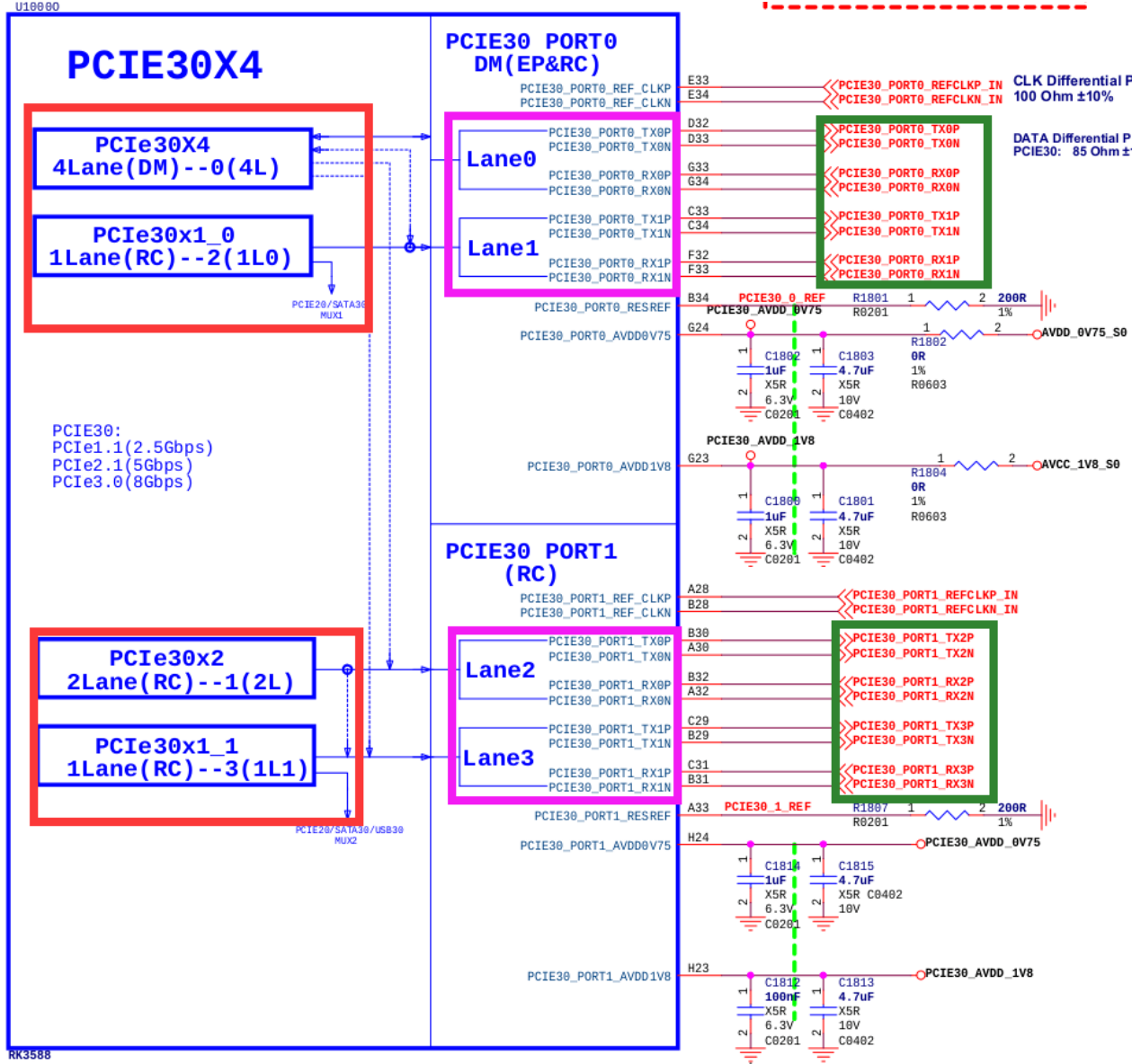
Original English figure — 30
The following figure is the RK3588 comboPHY and its possible controllers, with the red box representing the controller, the pink box representing the PHY signal, and the green box representing the peripheral signal; the actual controller used can be confirmed by the connection of peripheral signals, or checked with hardware engineers to understand if it is correct. In this figure, Mux0’s PHY (combphy0_ps) operates in SATA mode, not PCIe; Mux1’s PHY (combphy1_ps) works with PCIe30x1_0 (DTS named pcie2x1l0) and may operate in PCIe mode, which needs to be determined by the actual device connected; Mux2’s PHY (combphy2_psu) works with PCIe30x1_1 (DTS named pcie2x1l1) in PCIe mode for connecting a PCIe network card.
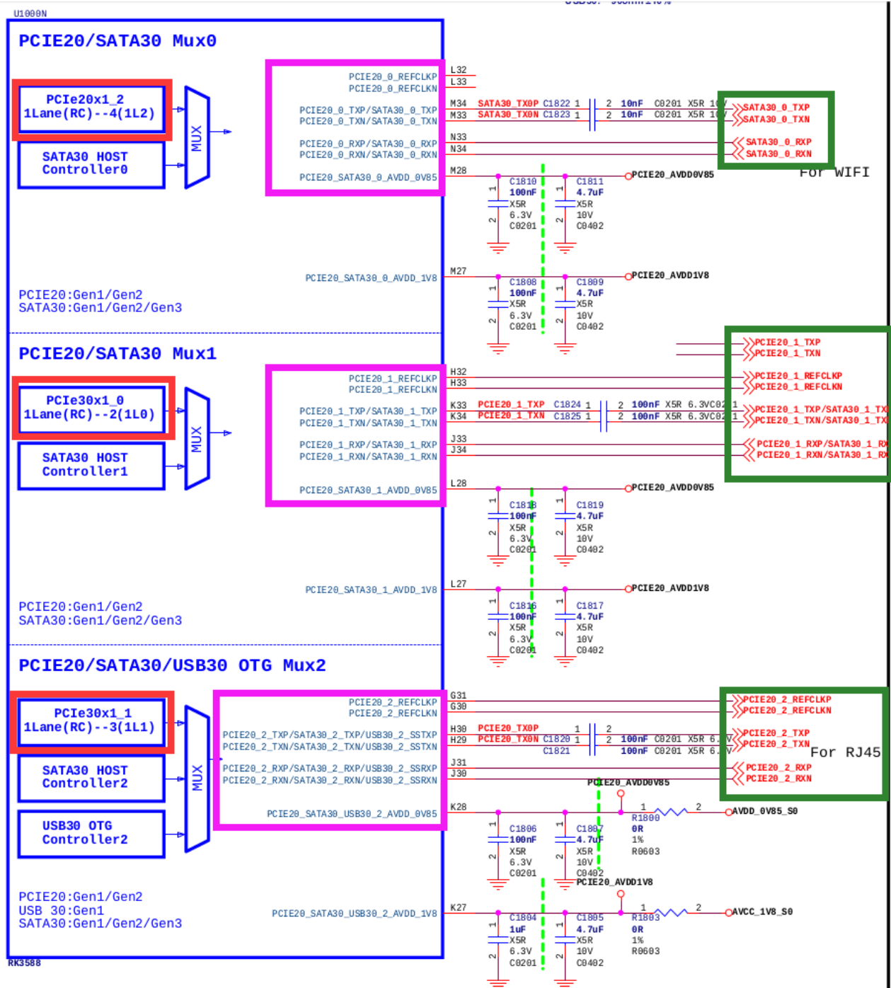
Original English figure — 31
The following figure shows the PCIe3.0 interface power supply of RK3588 evb1, which can be located by the signal PCIE30X4_PWREN_H corresponding to the RK3588 GPIO, and then filled into the pcie3x4 controller DTS.
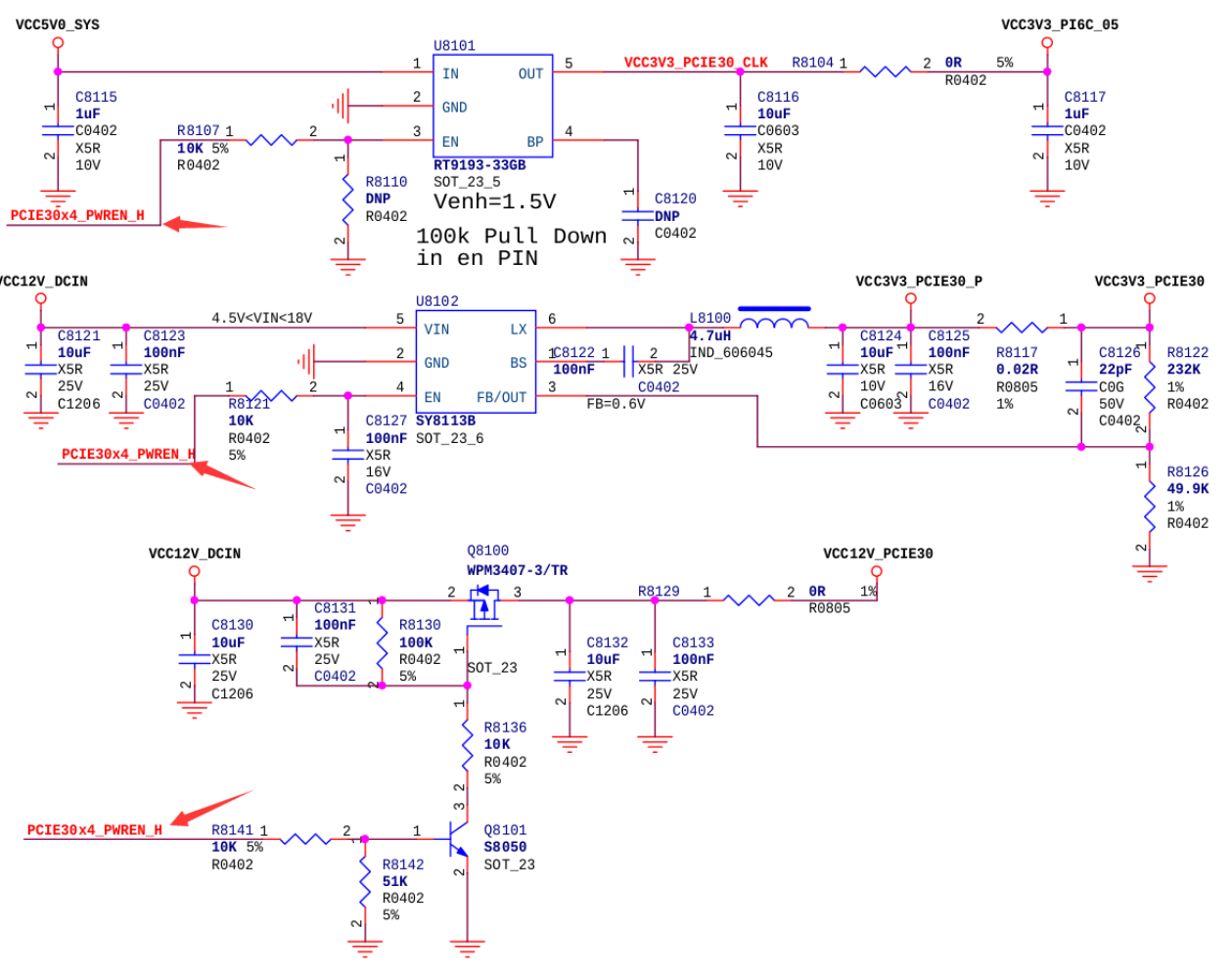
Original English figure — 32
2.8 Wi-Fi Module Device Tree Writing Example
Due to the Wi-Fi module generally connecting to the PCIe2.0 interface, its combphy multiplexing relationships are complex, and its power usage, sleep modes, and reset requirements are distinctly different from other devices. Here is a device tree writing example for reference.
- Review the schematic to understand the combphy used by the Wi-Fi module. The combphy node number indicates the Mux relationship, and the suffix indicates the multiplexing relationship, with p, s, u, q representing PCIe, SATA, USB, and QSGMII, respectively. Taking this diagram as an example, Wi-Fi is connected to the PCIe and SATA multiplexed PCIE20/SATA30 Mux0, so the configured should be the combphy0_ps node.
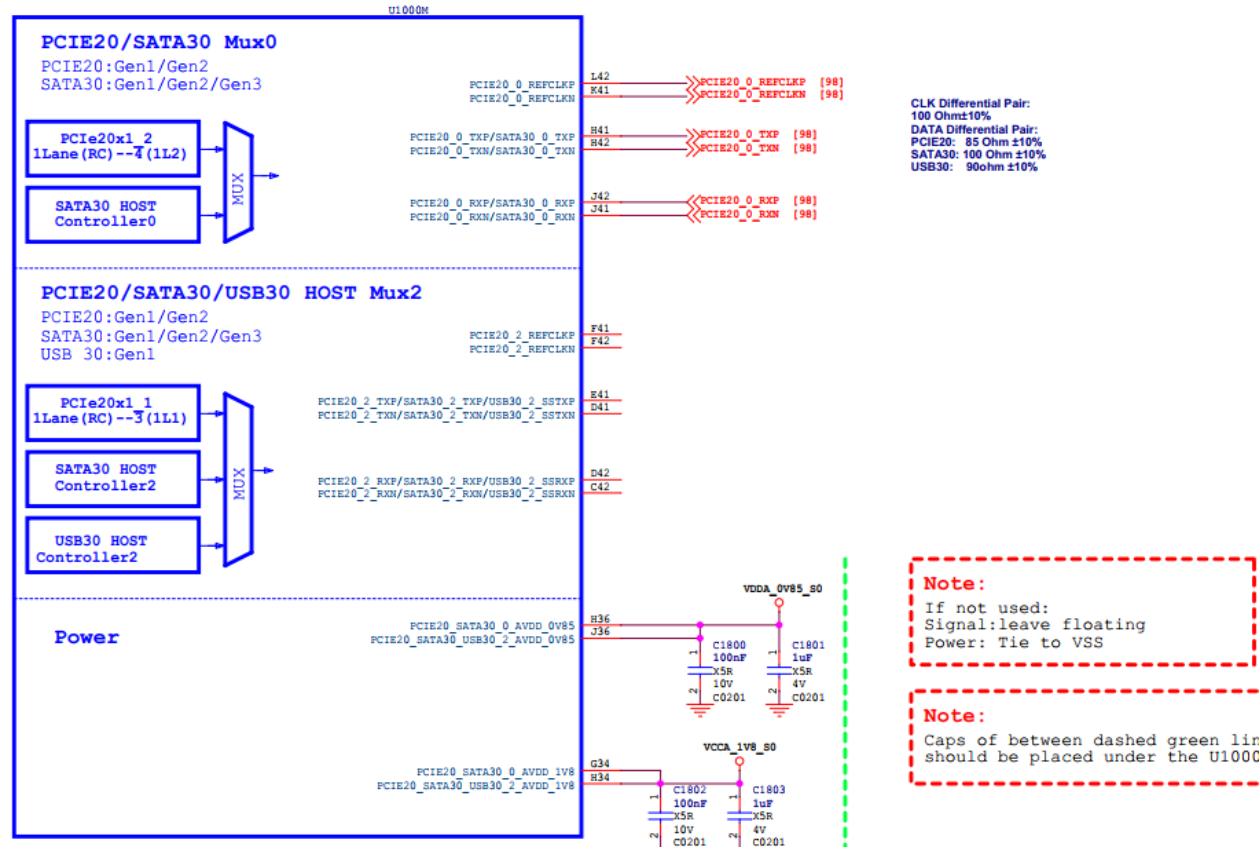
Original English figure — 33
- Search the dts file to ensure that other controller nodes using this combphy function are disabled to prevent signal interference.
- Move the wifi_reg_on signal from the wireless_wlan node to the PCIe 3.3v power control node.
- If Wi-Fi needs to achieve L1.x power consumption mode, please refer to the “RC mode PM L1 Substates Support” section.
- If Wi-Fi needs to implement wireless wake-up functionality, ensure that the wifi_reg_on pin remains high during sleep, and the wifi_host_wake pin is connected to the non-power-off PMU IO for generating interrupt wake-up to the main controller. For detailed hardware connections and software modifications, please refer to the relevant sections in our company’s SDK release documents, “Rockchip_Developer_Guide_Linux_WIFI_BT_CN.pdf”.
+ vcc3v3_pcie20_wifi: vcc3v3-pcie20-wifi {
+     compatible = "regulator-fixed";
+     regulator-name = "vcc3v3_pcie20_wifi";
+     regulator-min-microvolt = <3300000>;
+     regulator-max-microvolt = <3300000>;
+     enable-active-high;
+    /*
+     * wifi_reg_on is enabled after vbat and vddio are stable, pulled high before reset-gpios, so
+     * it is placed in the PCIe power node to meet the module timing, referring to wifi_poweren_gpio.
+     */
+     pinctrl-0 = <&wifi_poweren_gpio>;
+     startup-delay-us = <5000>;
+     vin-supply = <&vcc12v_dcin>;
+   };

    wireless_wlan: wireless-wlan {
        compatible = "wlan-platdata";
        wifi_chip_type = "ap6275p";
        pinctrl-names = "default";
        pinctrl-0 = <&wifi_host_wake_irq>;
        WIFI,host_wake_irq = <&gpio0 RK_PA0 GPIO_ACTIVE_HIGH>;
+       /* Note: The wifi_reg_on pin also needs to be configured here for the WiFi driver to control */
+       WIFI,poweren_gpio = <&gpio0 RK_PC7 GPIO_ACTIVE_HIGH>;
        status = "okay";
    };
+
+&sata0 {
+    status = "disabled" /* sata0 and pcie2x1l2 share combphy0_ps, ensure it is disabled */
+}
+
+&combphy0_ps {
+    status = "okay"; /* Ensure phy is enabled */
+};
+
+&pcie2x1l2 {
+    reset-gpios = <&gpio3 RK_PD1 GPIO_ACTIVE_HIGH>;
+    rockchip,skip-scan-in-resume;
+    rockchip,perst-inactive-ms = <500>; /* Refer to the Wi-Fi module manual for the required #PERST reset time */
+    vpcie3v3-supply = <&vcc3v3_pcie20_wifi>;
+    status = "okay";
+};

&pinctrl {
     wireless-wlan {
         wifi_poweren_gpio: wifi-poweren-gpio {
+            //PCIE REG ON: Be sure to configure it as pull-up
+            rockchip,pins = <0 RK_PC7 RK_FUNC_GPIO &pcfg_pull_up>;
         };
     };
};
3. menuconfig Configuration
- Ensure the following configurations are enabled to correctly use PCIe-related functions:
CONFIG_PCI=y
CONFIG_PCI_DOMAINS=y
CONFIG_PCI_DOMAINS_GENERIC=y
CONFIG_PCI_SYSCALL=y
CONFIG_PCI_BUS_ADDR_T_64BIT=y
CONFIG_PCI_MSI=y
CONFIG_PCI_MSI_IRQ_DOMAIN=y
CONFIG_PHY_ROCKCHIP_SNPS_PCIE3=y
CONFIG_PHY_ROCKCHIP_NANENG_COMBO_PHY=y
CONFIG_PCIE_DW=y
CONFIG_PCIE_DW_HOST=y
CONFIG_PCIE_DW_ROCKCHIP=y
CONFIG_PCIEPORTBUS=y
CONFIG_PCIE_PME=y
CONFIG_GENERIC_MSI_IRQ=y
CONFIG_GENERIC_MSI_IRQ_DOMAIN=y
CONFIG_IRQ_DOMAIN=y
CONFIG_IRQ_DOMAIN_HIERARCHY=y
- Enable NVMe devices (SSDs based on the PCIe interface), PCIe-to-AHCI devices (SATA), and PCIe-to-USB devices (XHCI) are all enabled in the default config, please confirm. For other devices such as Ethernet cards, WiFi, etc., please confirm the relevant config settings yourself.
CONFIG_BLK_DEV_NVME=y
CONFIG_SATA_PMP=y
CONFIG_SATA_AHCI=y
CONFIG_SATA_AHCI_PLATFORM=y
CONFIG_ATA_SFF=y
CONFIG_ATA=y
CONFIG_USB_XHCI_PCI=y
CONFIG_USB_XHCI_HCD=y
Special Note: The default kernel only supports PCIe-to-SATA devices listed in drivers/ata/ahci.c. For devices beyond this list, please seek support from the original manufacturer or distributor.
4. Standard EP Function Development
The PCIe controller of RK series chips supports EP mode, allowing the chips to be developed into standard PCIe EP products. For the implementation of EP functionality, please refer to the document “Rockchip_Developer_Guide_PCIE_EP_Standard_Card”.
5. RC mode PM L1 Substates Support
When it is confirmed that the RK main controller and the connected peripherals support PCIe PM L1 Substates, further optimization of power consumption can be achieved by enabling the PM L1 Substates feature. Further emphasis is placed on the fact that if there are devices among the target peripherals that do not support PM L1 Substates, especially if the motherboard design involves slot-connected non-fixed devices, do not enable the PM L1 Substates feature, as some devices may not function properly.
Notice The RK PCIe L1SS feature has a Tpower_on timing of less than 10us, which is not adjustable and is theoretically compatible with most peripherals. However, some peripherals have strict requirements for this specification, so it is recommended to further confirm the specification constraints with the original equipment manufacturers of the relevant peripherals. Hardware Circuit Design Supporting PM L1 Substates: Internal reference clock scheme: The CLKREQN signal of the Root Complex (RC) and the CLKREQN signal of the Endpoint (EP) are interconnected at both ends. External reference clock scheme: The CLKREQN signal of the Root Complex (RC) is connected to the enable pin (OE) of the CLOCK_GEN. If the enable pin (OE) of the CLOCK_GEN is active high, an inverter should be added.
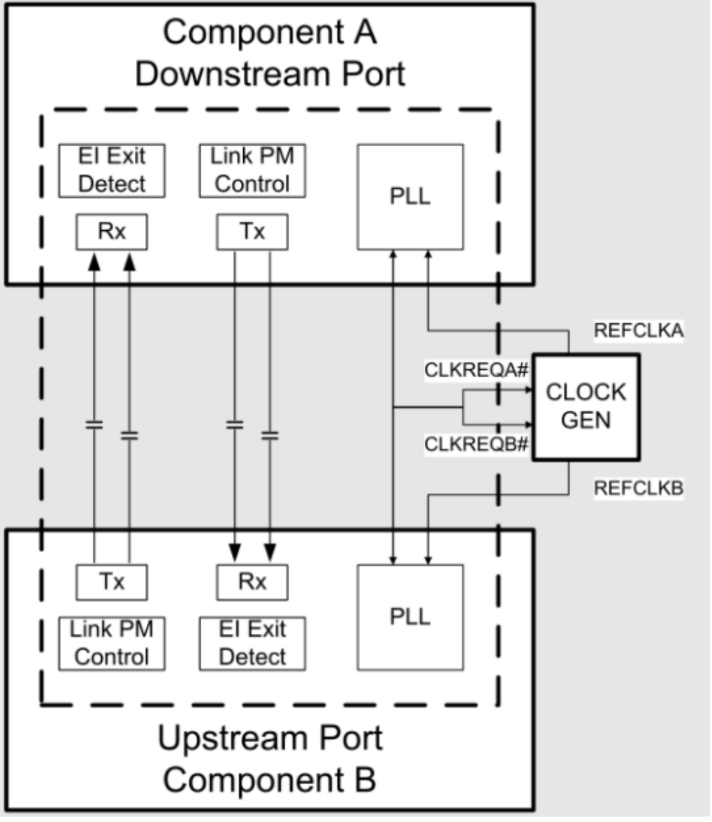
Original English figure — 36
The system does not enable PM L1 Substates support by default.: The “supports-clkreq;” property is not added in the dts. The kernel macro configuration CONFIG_PCIEASPM_POWER_SUPERSAVE=n.
System Enable PM L1 Substates Support Confirm that both RC/EP support PM L1 Substates, with the RC support status available in the “Chip Resource Introduction” section under the ASPM column. Hardware configuration of CLKREQN signal: Ensure compliance with “Hardware Circuit Design Supporting PM L1 Substates.” Software configuration of CLKREQN signal: Set CLKREQN iomux to function io. Software configuration of the controller node adds the “supports-clkreq;” property, for details refer to “DTS Configurable Item 11” explanation. Enable PM L1 Substates support: Method 1: Kernel macro configuration CONFIG_PCIEASPM_POWER_SUPERSAVE=y Method 2: Some peripherals, such as WIFI, support enabling PM L1 Substates in the driver. Explanation: If the above conditions are not strictly met and an attempt is made to enable the kernel macro configuration, the PCIe link may enter an abnormal state and fail to wake up. Please confirm that the kernel source code is up-to-date and includes the support patch for L1SS: commit e18dfa93 PCI: rockchip: dw: Support PM L1 clock removing.
6. GPIO-Based Detection Mechanism for Plug and Unplug Events
6.1 Hardware Requirements
- The PRSNTN_1 of the PCIe slot must be connected to any GPIO of the main controller to serve as a detection pin.
- The power supply of the PCIe device must be controllable by software for power on and off.
6.2 Software Requirements
- Submissions must include at least the following, if not, please contact the business for patches:
commit 4de1a0c19e0f9804ba22e7f5e544fea317913957
Author: Shawn Lin <shawn.lin@rockchip.com>
Date:   Tue Mar 12 16:38:46 2024 +0800

    PCI: rockchip: dw: Add gpio based hotplug
    Change-Id: I49c57755d11cc43bbf7cf9eb23542f5e1e11aaa3

commit 86f3010d7f523c9f5a2e88d9f8f1871ed89da098
Author: Vidya Sagar <vidyas@nvidia.com>
Date:   Sat Oct 1 00:57:45 2022 +0530

    FROMLIST: PCI/hotplug: Add GPIO PCIe hotplug driver
    Change-Id: Iafa798ee4d98f195f5d33d80120da0c569132548
- The kernel must confirm that the following configurations are enabled:
CONFIG_HOTPLUG_PCI=y
CONFIG_HOTPLUG_PCI_GPIO=y
- DTS configuration reference as follows
&pcie0 {
  reset-gpios = <&gpio4 RK_PC7 GPIO_ACTIVE_HIGH>;
  vpcie3v3-supply = <&vcc3v3_pcie0>;
  hotplug-gpios = <&gpio4 RK_PC4 IRQ_TYPE_EDGE_BOTH>;
  pinctrl-names = "default";
  pinctrl-0 = <&hot_plug0>;
  status = "okay";
};

&pinctrl {
  pcie {
      hot_plug0: hot-plug0 {
          rockchip,pins = <4 RK_PC4 RK_FUNC_GPIO &pcfg_pull_up>;
      };
  };
};
6.3 Usage Restrictions
- Hot-plugging of PCIe devices while powered can easily damage the device and the controller. The unloading and power-off procedures after device removal require some time, so rapid hot-plugging is prohibited. Wait until the following removal log appears before reinserting:
[   35.680289][  T134] pcieport 0000:00:00.0: Hot-UnPlug Event
[   35.680361][  T134] pcieport 0000:00:00.0: Power Status = 1
[   35.827183][  T134] rk-pcie 2a200000.pcie: rk_pcie_slot_disable
[   35.827303][  T134] pcieport 0000:00:00.0: Hot-UnPlug Event
[   35.827323][  T134] pcieport 0000:00:00.0: Power Status = 0
[   35.827334][  T134] pcieport 0000:00:00.0: Device is already removed
- To ensure data integrity and system stability, it is necessary to ensure that the system stops accessing the device to be removed.
- It is not possible to support the individual hot-plugging of downstream devices of the switch. If there is such a need, first confirm that the switch supports individual hot-plugging of downstream devices, then refer to the “How to rescan or replace a single downstream device online?” section in the common application issues for rescan processing, which can achieve the same effect.
- It is not supported to detect the insertion or removal of devices in a sleep or standby state.
7. Kernel DMATEST
Before development, please confirm whether the target PCIe controller supports DMA transfer, refer to the “Chip Resource Introduction” section for details. RK PCIe DMA provides a test mechanism based on the kernel module_para mechanism, similar to the Linux dmatest framework, which can be further developed for kernel-level PCIe DMA applications. Kernel Version Requirements Include at least the following commit, if not, please contact the business for patches:
commit a7c40cb119703e566d9d5befb8c1a7b0533dd7b7
Author: Jon Lin <jon.lin@rock-chips.com>
Date:   Tue Jan 17 17:46:48 2023 +0800

    PCI: rockchip: dw-dmatest: Suppport rc dma

    1.Set rc dma as default
    2.Changet to ep dma by sending command:
            echo 0 > ./sys/module/pcie_dw_dmatest/parameters/is_rc

    Change-Id: I9b16c328c08f220772e487c7c796b8898d74ae10
    Signed-off-by: Jon Lin <jon.lin@rock-chips.com>
Test Macro Configuration
CONFIG_PCIE_DW_DMATEST=y
CONFIG_ROCKCHIP_PCIE_DMA_OBJ=n
Setting Up the Environment PCIe Interconnection Model:
Customers set up RK RC - FPGA EP environment on their own RK local testing setup is RK RC (RK dmatest configuration) - RK EP (RK chip interconnection configuration) Notes: MPS configuration is 256B Both RC and EP require reserved memory, it is recommended to reserve 64MB of test memory at 0x3c000000 (the default configuration address for testing) It is recommended to disable other unrelated PCIe controllers Testing Refer to the pcie-dw-misc-dmatest.c source code for details.
static int size = 0x20;
module_param(size, int, 0644);
MODULE_PARM_DESC(size, "each packet size in bytes");

static unsigned int cycles_count = 1;
module_param(cycles_count, uint, 0644);
MODULE_PARM_DESC(cycles_count, "how many erase cycles to do (default 1)");

static bool irq;
module_param(irq, bool, 0644);
MODULE_PARM_DESC(irq, "Using irq? (default: false)");

static unsigned int chn_en = 1;
module_param(chn_en, uint, 0644);
MODULE_PARM_DESC(chn_en, "Each bits for one dma channel, up to 2 channels, (default enable chanel 0)");

static unsigned int rw_test = 3;
module_param(rw_test, uint, 0644);
MODULE_PARM_DESC(rw_test, "Read/Write test, 1-read 2-write 3-both(default 3)");

static unsigned int bus_addr = 0x3c000000;
module_param(bus_addr, uint, 0644);
MODULE_PARM_DESC(bus_addr, "Dmatest chn0 bus_addr(remote), chn1 add offset 0x100000, (default 0x3c000000)");

static unsigned int local_addr = 0x3c000000;
module_param(local_addr, uint, 0644);
MODULE_PARM_DESC(local_addr, "Dmatest chn0 local_addr(local), chn1 add offset 0x100000, (default 0x3c000000)");

static unsigned int test_dev;
module_param(test_dev, uint, 0644);
MODULE_PARM_DESC(test_dev, "Choose dma_obj device,(default 0)");

static bool is_rc = true;
module_param_named(is_rc, is_rc, bool, 0644);
MODULE_PARM_DESC(is_rc, "Test port is rc(default true)");
Example Reference 1: RC device, channel 0, write data, data granularity 1MB, loop count 1000, local address 0x3c000000, remote address 0x3c000000:
echo 0 > ./sys/module/pcie_dw_dmatest/parameters/test_dev
echo 1 > ./sys/module/pcie_dw_dmatest/parameters/is_rc
echo 1 > ./sys/module/pcie_dw_dmatest/parameters/chn_en
echo 1 > ./sys/module/pcie_dw_dmatest/parameters/rw_test
echo 0x100000 > ./sys/module/pcie_dw_dmatest/parameters/size
echo 1000 > ./sys/module/pcie_dw_dmatest/parameters/cycles_count
echo 0x3c000000 > ./sys/module/pcie_dw_dmatest/parameters/local_addr
echo 0x3c000000 > ./sys/module/pcie_dw_dmatest/parameters/bus_addr
echo run > ./sys/module/pcie_dw_dmatest/parameters/dmatest
Example Reference 2: EP device, channel 0/1 (dual-threaded operation), read/write data, data granularity 8KB, loop count 10000, local address 0x3c000000, remote address 0x3c000000:
echo 0 > ./sys/module/pcie_dw_dmatest/parameters/test_dev
echo 0 > ./sys/module/pcie_dw_dmatest/parameters/is_rc
echo 3 > ./sys/module/pcie_dw_dmatest/parameters/chn_en
echo 3 > ./sys/module/pcie_dw_dmatest/parameters/rw_test
echo 0x2000 > ./sys/module/pcie_dw_dmatest/parameters/size
echo 10000 > ./sys/module/pcie_dw_dmatest/parameters/cycles_count
echo 0x3c000000 > ./sys/module/pcie_dw_dmatest/parameters/local_addr
echo 0x3c000000 > ./sys/module/pcie_dw_dmatest/parameters/bus_addr
echo run > ./sys/module/pcie_dw_dmatest/parameters/dmatest
8. Kernel Stability Statistics
PCIe devices may deviate from expected behavior during long operation. Retrieve debugfs information for analysis. Ensure commit pcie: rockchip: dw: Add debugfs support is included; otherwise obtain 0001-pcie-rockchip-dw-Add-debugfs-support.patch from Redmine as described in the appendix. Usage:
- Identify the controller address node of the problematic device, which can be found in the boot enumeration log or directly from the dtsi.
- Taking fe16000.pcie as an example, navigate to the /sys/kernel/debug/fe160000.pcie directory.
- echo disable > err_event to disable all event statistics functions.
- echo clear > err_event to clear all event statistics counters.
- echo enable > err_event to enable all event statistics functions.
- Begin device aging to reproduce your exceptional case. After reproduction, execute cat dumpfifo and cat err_event .
- Compare the exported information with the Debugfs Export Information Parsing Table in the appendix of this document to roughly identify the issue.
9. Kernel AER support and Injection Test Support
The AER (Advanced Error Reporting) function is a standard component provided by the Linux framework. It reports underlying communication errors to various user-space daemons and establishes fault-tolerant handling mechanisms. In complex business environments, AER injection testing can simulate various AER events in advance to improve exception handling procedures.
- Enable kernel AER and injection support to create the /dev/aer_inject node in the system:
CONFIG_PCIEAER=y
CONFIG_PCIEAER_INJECT=y
- Configure kernel’s cmdline
#Use RK3588-EVB Linux for example,  add pcie_pme=nomsi
--- a/arch/arm64/boot/dts/rockchip/rk3588-linux.dtsi
+++ b/arch/arm64/boot/dts/rockchip/rk3588-linux.dtsi
@@ -12,7 +12,7 @@ aliases {
        };

        chosen: chosen {
-               bootargs = "earlycon=uart8250,mmio32,0xfeb50000 console=ttyFIQ0 irqchip.gicv3_pseudo_nmi=0 root=PARTUUID=614e0000-0000 rw rootwait rcupdate.rcu_expedited=1 rcu_nocbs=all";
+               bootargs = "earlycon=uart8250,mmio32,0xfeb50000 console=ttyFIQ0 irqchip.gicv3_pseudo_nmi=0 root=PARTUUID=614e0000-0000 rw rootwait rcupdate.rcu_expedited=1 rcu_nocbs=all pcie_pme=nomsi";
        };
- Make sure we get it right and register aer irq service
# check the cmdline for sure we set pcie_pme=nomsi
cat /proc/cmdline
# check the irq
root@debian:/userdata# cat /proc/interrupts | grep aerdrv
 60:      0      0      0      0      0      0     0     0     INTx   0 Edge      PCIe PME, aerdrv, PCIe bwctrl
 63:      0      0      0      1      0      0     0     0     INTx   0 Edge      PCIe PME, aerdrv
110:      0      0      0      0      0      0     0     0     INTx   0 Edge      PCIe PME, aerdrv
- Obtain the AER injection tool aer-inject from the “Development Resource Acquisition Address” mentioned in the appendix of this document.
- Query the address of the target PCIe device for testing:
# Use lspci to obtain the PCIe device address. Example with network card 01:00.0:
00:00.0 PCI bridge: Rockchip Electronics Co., Ltd Device 3576 (rev 01)
01:00.0 Network controller: Broadcom Inc. and subsidiaries Device 449d (rev 02)
- Create a test script (example):
# Example script name: aer.txt, content:

AER
BUS 1 DEV 0 FN 0        // BUS, DEV, FN correspond to the BDF of the DUT (Device Under Test)
COR_STATUS BAD_TLP      // Test correctable error: bad TLP
HEADER_LOG 0 1 2 3

AER
BUS 1 DEV 0 FN 0        // BUS, DEV, FN correspond to the BDF of the DUT
UNCOR_STATUS COMP_ABORT // Test uncorrectable error: completion abort
HEADER_LOG 4 5 6 7
For correctable errors, besides BAD_TLP , valid types include: RCVR , BAD_DLLP , REP_ROLL , REP_TIMER . For uncorrectable errors, besides COMP_ABORT , valid types include: TRAIN , DLP , POISON_TLP , FCP , COMP_TIME , UNX_COM , RX_OVE , MALF_TLP , ECRC , UNSUP . A single script can execute various injection configurations. Customize as needed.
- Execute the test script:
root@rk3576-buildroot:/data# ./aer-inject aer.txt
[  459.689869] pcieport 0000:00:00.0: aer_inject: Injecting errors 00000040/00000000 into device 0000:01:00.0
[  459.690302] pcieport 0000:00:00.0: AER: Corrected error message received from 0000:01:00.0
[  459.690376] pci 0000:01:00.0: PCIe Bus Error: severity=Corrected, type=Data Link Layer, (Receiver ID)
[  459.690404] pci 0000:01:00.0:   device [14e4:449d] error status/mask=00000040/00002000
[  459.690434] pci 0000:01:00.0:    [ 6] BadTLP
10. Kernel Error Injection Test Support
If the PCIe link requires testing the RC endpoint function driver, business model/EP endpoint firmware/duplex hardware IP error tolerance, error injection testing can be enabled to simulate the types of errors that may occur during the interaction between the two parties, and assess the stability of the dual-end software and IP. Usage method:
(1) The following commit needs to be included
commit fe835d5fd3329ba629f8c4290c818ef4b8f9895d
Author: Shawn Lin <shawn.lin@rock-chips.com>
Date:   Wed Sep 4 17:04:37 2024 +0800

    PCI: rockchip: dw: Add fault injection support
    Change-Id: Ib214cc1be565bf16bafb6a847215572f35c43753

(2) The functionality described in the "Kernel Stability Statistical Information" section of this document needs to be enabled, and the corresponding controller directory needs to be entered

(3) echo "einj_number enable_or_disable error_type error_number" > fault_injection
    |-------------------|----------------------------------------------------------|
    | Value             |         Meaning                                            |
    |-------------------|----------------------------------------------------------|
    |einj_number:       |Error injection group number, only supports 0 to 6, other values are invalid                         |
    |-------------------|----------------------------------------------------------|
    |enable_or_disable: |Enable or disable error injection, 0 means disable, 1 means enable, other values are invalid      |
    |-------------------|----------------------------------------------------------|
    |error_type:        |Error injection type selection, choose the error type corresponding to the einj_number group number as described in the appendix|
    |-------------------|----------------------------------------------------------|
    |error_number:      |Error injection quantity, only supports 0 to 255, other values are invalid                         |
    |-------------------|----------------------------------------------------------|
    For example, echo "2 1 2 128" > fault_injection, represents enabling einj2 and injecting 128 NAK DLLP packets

(4) Start the PCIe link transmission, for example, NVMe: dd if=/dev/nvme0n1 of=/dev/null bs=1M count=5000

(5) Check if the error occurs: cat err_event
    Rx Recovery Request: 0x1f
    ...
    Tx Nak DLLP: 0x80

(6) Analyze the dual-end software and hardware to see if there are any unexpected software or hardware exceptions
11. Kernel PMU perf Support
11.1 Software and Configuration
(1) The following five commits must be included:
commit 0270f32f207f5682a729c17e977eb87bba83823e
Author: Shuai Xue <xueshuai@linux.alibaba.com>
Date:   Fri Dec 8 10:56:50 2023 +0800
    UPSTREAM: PCI: Move pci_clear_and_set_dword() helper to PCI header
    Change-Id: I35125190a4dd8ba25e6ec14b4712750605c22285

commit 1b627c690ade9a72e3cd488e2e11edffb5d0e879
Author: Shuai Xue <xueshuai@linux.alibaba.com>
Date:   Fri Dec 8 10:56:49 2023 +0800

    UPSTREAM: PCI: Add Alibaba Vendor ID to linux/pci_ids.h
    Change-Id: I86188f119a42548ab777df0449f7d0a933f34d12

commit dcfa6c8947baeac74ab44ea8f03d3831a062c14b
Author: Shuai Xue <xueshuai@linux.alibaba.com>
Date:   Fri Dec 8 10:56:51 2023 +0800

    BACKPORT: drivers/perf: add DesignWare PCIe PMU driver
    Change-Id: I470f4dc2791168760517c77dd31a4dacd7dab591

commit 6cb6a00862fa29f815412634569e2015f86e397a
Author: Shawn Lin <shawn.lin@rock-chips.com>
Date:   Tue Sep 3 16:24:36 2024 +0800

    perf/dwc_pcie: Add support for Rockchip vendor devices
    Change-Id: I6fde80440d2fa058b38a7d927eb846f477812b5f

commit 50cb3fcd18fb9defe23ba95eb3962a287e957166
Author: Shawn Lin <shawn.lin@rock-chips.com>
Date:   Tue Sep 3 16:24:36 2024 +0800

    PCI: rockchip: dw: Add dwc pmu support for rockchip
    Change-Id: Ia27ee055aa3e63deeb7fd646411c3542b7019288

(2) The kernel must enable the CONFIG_PERF_EVENTS configuration.
(3) The system must integrate the perf tool; if not available, it can be downloaded from the development resource access address mentioned in the appendix of this document.
11.2 Usage Instructions
(1) List all configurations supported by DWC PCIe PMU
root@rk3576-buildroot:/# /userdata/perf list | grep dwc_rootport
  dwc_rootport_0/CFG_RCVRY/                          [Kernel PMU event] #Percentage of time link is in rcvry state
  dwc_rootport_0/L0/                                 [Kernel PMU event] #Percentage of time link is in L0 state
  dwc_rootport_0/L1/                                 [Kernel PMU event] #Percentage of time link is in L1 state
  dwc_rootport_0/L1_1/                               [Kernel PMU event] #Percentage of time link is in L1.1 state
  dwc_rootport_0/L1_2/                               [Kernel PMU event] #Percentage of time link is in L1.2 state
  dwc_rootport_0/L1_AUX/                             [Kernel PMU event] #Status not supported by RK
  dwc_rootport_0/RX_L0S/                             [Kernel PMU event] #Percentage of time RX is in L0s state
  dwc_rootport_0/Rx_CCIX_TLP_Data_Payload/           [Kernel PMU event] #RK does not support CCIX data statistics
  dwc_rootport_0/Rx_PCIe_TLP_Data_Payload/           [Kernel PMU event] #RX TLP data volume
  dwc_rootport_0/TX_L0S/                             [Kernel PMU event] #Percentage of time TX is in L0s state
  dwc_rootport_0/TX_RX_L0S/                          [Kernel PMU event] #Percentage of time both TX and RX are in L0s state
  dwc_rootport_0/Tx_CCIX_TLP_Data_Payload/           [Kernel PMU event] #RK does not support CCIX data statistics
  dwc_rootport_0/Tx_PCIe_TLP_Data_Payload/           [Kernel PMU event] #TX TLP data volume
  dwc_rootport_0/one_cycle/                          [Kernel PMU event] #Not supported by RK
  dwc_rootport_0/rx_ack_dllp,lane=?/                 [Kernel PMU event] #Number of DLLPs acknowledged by RX
  dwc_rootport_0/rx_atomic,lane=?/                   [Kernel PMU event] #Not supported by RK
  dwc_rootport_0/rx_ccix_tlp,lane=?/                 [Kernel PMU event] #Not supported by RK
  dwc_rootport_0/rx_completion_with_data,lane=?/     [Kernel PMU event] #RX completion packets with data
  dwc_rootport_0/rx_completion_without_data,lane=?/  [Kernel PMU event] #RX completion packets without data
  dwc_rootport_0/rx_duplicate_tl,lane=?/             [Kernel PMU event] #Number of RX/TL dup errors
  dwc_rootport_0/rx_io_read,lane=?/                  [Kernel PMU event] #Number of ior packets on RX
  dwc_rootport_0/rx_io_write,lane=?/                 [Kernel PMU event] #Number of iow packets on RX
  dwc_rootport_0/rx_memory_read,lane=?/              [Kernel PMU event] #Number of memr packets on RX
  dwc_rootport_0/rx_memory_write,lane=?/             [Kernel PMU event] #Number of memw packets on RX
  dwc_rootport_0/rx_message_tlp,lane=?/              [Kernel PMU event] #Number of messages received on RX
  dwc_rootport_0/rx_nulified_tlp,lane=?/             [Kernel PMU event] #Number of TLPs discarded due to errors on RX
  dwc_rootport_0/rx_tlp_with_prefix,lane=?/          [Kernel PMU event] #Number of TLPs with prefix on RX
  dwc_rootport_0/rx_update_fc_dllp,lane=?/           [Kernel PMU event] #Number of flow control packets received on RX
  dwc_rootport_0/tx_ack_dllp,lane=?/                 [Kernel PMU event] #Number of DLLPs acknowledged by TX
  dwc_rootport_0/tx_atomic,lane=?/                   [Kernel PMU event] #Not supported by RK
  dwc_rootport_0/tx_ccix_tlp,lane=?/                 [Kernel PMU event] #Not supported by RK
  dwc_rootport_0/tx_completion_with_data,lane=?/     [Kernel PMU event] #TX completion packets with data
  dwc_rootport_0/tx_completion_without_data,lane=?/  [Kernel PMU event] #TX completion packets without data
  dwc_rootport_0/tx_configuration_read,lane=?/       [Kernel PMU event] #Number of cfg-r packets on TX
  dwc_rootport_0/tx_configuration_write,lane=?/      [Kernel PMU event] #Number of cfg-w packets on TX
  dwc_rootport_0/tx_io_read,lane=?/                  [Kernel PMU event] #Number of ior packets on TX
  dwc_rootport_0/tx_io_write,lane=?/                 [Kernel PMU event] #Number of iow packets on TX
  dwc_rootport_0/tx_memory_read,lane=?/              [Kernel PMU event] #Number of memr packets on TX
  dwc_rootport_0/tx_memory_write,lane=?/             [Kernel PMU event] #Number of memw packets on TX
  dwc_rootport_0/tx_message_tlp,lane=?/              [Kernel PMU event] #Number of messages received on TX
  dwc_rootport_0/tx_nulified_tlp,lane=?/             [Kernel PMU event] #Number of TLPs discarded due to errors on TX
  dwc_rootport_0/tx_tlp_with_prefix,lane=?/          [Kernel PMU event] #Number of TLPs with prefix sent by TX
  dwc_rootport_0/tx_update_fc_dllp,lane=?/           [Kernel PMU event] #Number of flow control packets sent by TX

(2) Start a perf feature, using time-based statistics for RX TLP as an example
 /userdata/perf stat -a -e dwc_rootport_0/Rx_PCIe_TLP_Data_Payload/

(3) Initiate transmission
root@rk3576-buildroot:/# dd if=/dev/nvme0n1 of=/dev/null bs=1M count=5000
dd if=/dev/nvme0n1 of=/dev/null bs=1M count=5000
5000+0 records in
5000+0 records out
5242880000 bytes (5.2 GB, 4.9 GiB) copied, 14.9016 s, 352 MB/s

(4) View statistics
Performance counter stats for 'system wide':
5221423060      dwc_rootport_0/Rx_PCIe_TLP_Data_Payload/     (50.01%)
28.298528222 seconds time elapsed

(5) Similarly, test the data volume of TX TLP, and calculate the average RX/TX bandwidth
PCIe RX Bandwidth = Rx_PCIe_TLP_Data_Payload / duration
PCIe TX Bandwidth = Tx_PCIe_TLP_Data_Payload / duration

(6) Statistics for Lane events
Since each Lane has the same events, to avoid generating a large amount of redundant information, it is recommended to specify the Lane ID, for example:
 /userdata/perf stat -a -e dwc_rootport_0/rx_memory_read,lane=1/
12. Common Application Issues
12.1 Can lanes be interwoven when the routing position is not optimal?
- Support for lane interweaving (Lane reversal) is a hardware protocol behavior, and no software changes are required. However, there are the following restrictions: In the case of 4 lanes, the RK platform currently only supports full reverse interweaving, meaning that RC’s Lane[0.1.2.3] correspond to EP’s Lane[3.2.1.0], and all other scenarios are not supported.
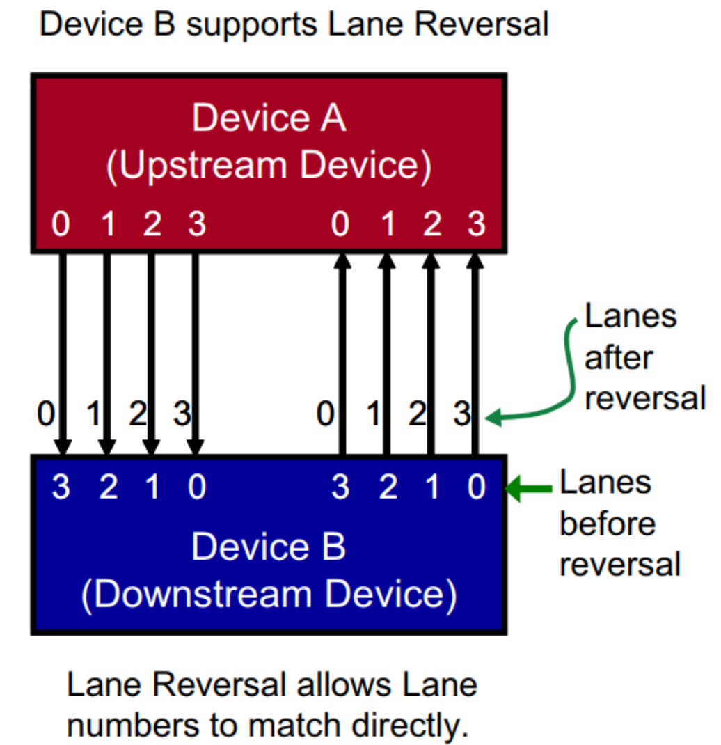
Original English figure — 48
In the case of 2 lanes, similarly, RC’s Lane[0.1] correspond to EP’s Lane[1.0].
- It is not supported to combine signals from different groups of lanes on the same side, such as RC lane0 TX and lane1 RX cannot be combined into a group of lanes to connect external devices.
12.2 Can Differential Signals on the Same Lane be Intertwined?
Supports PN inversion (Lane polarity), typically RC TX+ connects to EP RX+, RC TX- connects to EP RX-, supports PN inversion wiring such as RC TX+ connecting to EP RX-, and no additional software processing is required, as the PCIe controller automatically detects it. Does not support TX/RX intertwining, for example, RC’s lane1 TX cannot be connected to EP’s lane1TX.
12.3 Can a Single PCIe Interface Support Splitting or Merging?
Some PCIe ports on RK chips can support the functions of splitting and merging. Please refer to the “Chip Resources Introduction” section for details, and refer to the example and dts explanation for specific methods.
12.4 What Clock Input Modes Does PCIe 3.0 Interface Support?
The input clock modes for the PHY of PCIe 3.0 can be HCSL, LPHCSL, or other differential signals, such as LVDS with additional level conversion circuit implementations, all of which are designed to meet the PHY specifications.
Original English figure — 49
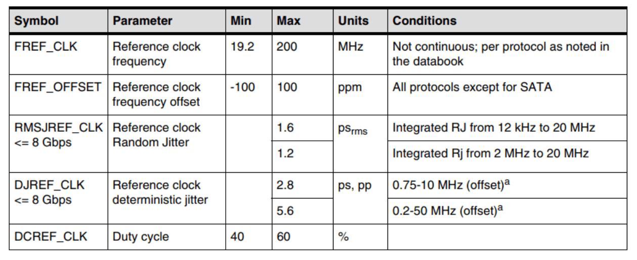
Original English figure — 49
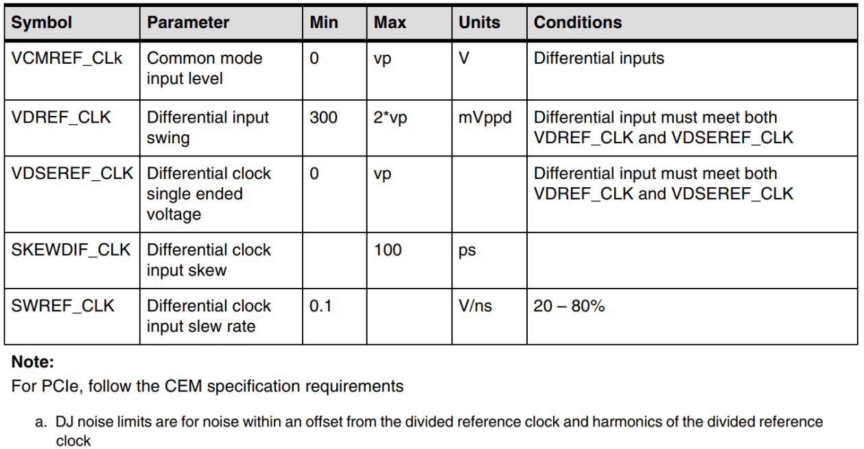
Original English figure — 50
Editable transcription of the source figures
| Symbol | Parameter | Min | Max | Units | Conditions |
|---|---|---|---|---|---|
| FREF_CLK | Reference clock frequency | 19.2 | 200 | MHz | Not continuous; per protocol as noted in the databook |
| FREF_OFFSET | Reference clock frequency offset | -100 | 100 | ppm | All protocols except SATA |
| RMSJREF_CLK <= 8 Gbps | Reference clock random jitter | 1.6 | ps_rms | Integrated RJ from 12 kHz to 20 MHz | |
| RMSJREF_CLK <= 8 Gbps | Reference clock random jitter | 1.2 | ps_rms | Integrated RJ from 2 MHz to 20 MHz | |
| DJREF_CLK <= 8 Gbps | Reference clock deterministic jitter | 2.8 | ps, pp | 0.75–10 MHz (offset), a | |
| DJREF_CLK <= 8 Gbps | Reference clock deterministic jitter | 5.6 | ps, pp | 0.2–50 MHz (offset), a | |
| DCREF_CLK | Duty cycle | 40 | 60 | % | |
| VCMREF_CLK | Common-mode input level | 0 | vp | V | Differential inputs |
| VDREF_CLK | Differential input swing | 300 | 2*vp | mVppd | Differential input must meet both VDREF_CLK and VDSEREF_CLK |
| VDSEREF_CLK | Differential clock single-ended voltage | 0 | vp | Differential input must meet both VDREF_CLK and VDSEREF_CLK | |
| SKEWDIF_CLK | Differential clock input skew | 100 | ps | ||
| SWREF_CLK | Differential clock input slew rate | 0.1 | V/ns | 20–80% |
For PCIe, follow the CEM specification requirements. Footnote a: DJ noise limits apply within an offset from the divided reference clock and its harmonics. Blank cells remain blank as in the source.
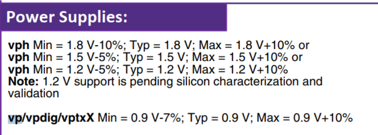
1.2 V support is pending silicon characterization and validation in the source; it is not a verified ArmSoM operating point.
| vph / vp/vpdig/vptxX | Min | Typ | Max |
|---|---|---|---|
| vph | 1.8 V -10% | 1.8 V | 1.8 V +10% |
| vph | 1.5 V -5% | 1.5 V | 1.5 V +10% |
| vph | 1.2 V -5% | 1.2 V | 1.2 V +10% |
| vp/vpdig/vptxX | 0.9 V -7% | 0.9 V | 0.9 V +10% |
12.5 Does PCIe switch support exist? Are there any recommendations from your company?
12.6 How to Determine the Correspondence Between Controllers and Devices in the System?
Taking the RK3568 chip as an example: The PCIe2x1 controller allocates Bus addresses for peripherals between 0x0~0xf, the PCIe3x1 controller allocates bus addresses between 0x10~0x1f, and the PCIe3x2 controller allocates bus addresses between 0x20~0x2f. From the output of lspci, you can see the bus addresses (high bits) allocated to each device, which allows you to determine the correspondence. The second column Class is the device type, and the third column VID:PID. Class types can be referenced at https://pci-ids.ucw.cz/read/PD/, and vendor VID and product PID can be referenced at http://pci-ids.ucw.cz/v2.2/pci.ids
console:/ # lspci
21:00.0 Class 0108: 144d:a808
20:00.0 Class 0604: 1d87:3566
11:00.0 Class 0c03: 1912:0014
10:00.0 Class 0604: 1d87:3566
01:00.0 Class 0c03: 1912:0014
00:00.0 Class 0604: 1d87:3566
We can see that each controller reserves 16 levels of bus downstream to connect devices, which means each controller can connect 16 devices downstream (including switches), generally meeting the requirements. Readers can skip the following explanation if not necessary. If adjustments are indeed required, please adjust the bus-range allocation of the three controllers in rk3568.dtsi, and ensure that there is no overlap.
Additionally, adjusting the bus-range will cause changes in the MSI(-X) RID intervals of devices, so please adjust the msi-map accordingly.
bus-range = <start address   end address>

msi-map = < start address in bus-range << 8
            &its
            start address in bus-range << 8
            total number of buses allocated in bus-range << 8>
For example, if the bus-range is adjusted to 0x30 ~ 0x60, meaning devices downstream of this controller are allocated bus addresses from 0x30 to 0x60, with a total of 0x30 buses, then you can configure msi-map = <0x3000 &its 0x3000 0x3000> And so on, and it is essential to ensure that the bus-range and msi-map of the three controllers do not overlap with each other, and that the bus-range and msi-map are compatible with each other.
12.7 How to Determine the Link Status of a PCIe Device?
Use the lspci tool published by the server to execute lspci -vvv to find the corresponding device’s linkStat to view it; where Speed indicates the speed, and Width refers to the number of lanes. If you need to parse other information, please search the internet for reference.
12.7a MSI allocation capacity (Chinese-source supplement)
This paragraph is present in Chinese V6.29.0 §12.8 (p.46) but absent from the corresponding English edition. The number assignable to PCIe devices depends on interrupt-controller resources. For all downstream devices of each controller, RK1808/RK3566/RK3568/RK3588 provide a total of 65535 MSI interrupts; RK3528/RK3562/RK3576 provide a total of 32. These are source claims, not measured ArmSoM results.
12.8 Does it support Legacy INT mode? How to force the use of Legacy INTA to INTD interrupts?
It supports the legacy INT mode. However, the default priority of the Linux PCIe protocol stack is MSI-X, MSI, Legacy INT, so conventionally available devices will not request Legacy INT. If debugging and testing are required, please refer to the Documentation/admin-guide/kernel-parameters.txt document in the kernel, where “pci=option[,option…] [PCI] various PCI subsystem options.” describes that MSI can be disabled in the cmdline, and the system will default to forcing the use of the Legacy INT allocation mechanism. Taking the RK356X Android platform as an example, an additional item pci=nomsi can be added to the cmdline parameters in arch/arm64/boot/dts/rockchip/rk3568-android.dtsi, noting that there should be a space before and after the item:
bootargs = "...... pci=nomsi ......";
If added successfully, lspci -vvv will show that the MSI and MSI-X for this device are both disabled (Enable-), and INT A interrupt is allocated, with the interrupt number being 80. cat /proc/interrupts can be used to view the status of the 80 interrupt.
01:00.0 Class 0108: Device 14a4:22f1 (rev 01) (prog-if 02)
        Subsystem: Device 1b4b:1093
...
        Interrupt: pin A routed to IRQ 80
...
        Capabilities: [50] MSI: Enable- Count=1/1 Maskable+ 64bit+
                Address: 0000000000000000  Data: 0000
                Masking: 00000000  Pending: 00000000
...
        Capabilities: [b0] MSI-X: Enable- Count=19 Masked-
                Vector table: BAR=0 offset=00002000
                PBA: BAR=0 offset=00003000
12.9 How to Access BAR Space if the CPU Runs in 32-bit Address Mode?
By default, the chip allocates BAR space for the PCIe controller, which is located beyond the 32-bit addressing range. However, our chip has reserved a BAR address below 32 bits, with different limitations for each controller. For instance, the RK3568 chip has only 32MB of low-position BAR address for each controller. When the RK3568 CPU operates in 32-bit address mode, we should enable the low address space to reallocate the ranges for each PCIe node. The following example has been modified to configure a 1MB configuration space, 1MB IO space, and 30MB 32-bit MEM space:
&pcie2x1 {
        ranges = <0x00000800 0x0 0xF4000000 0x0 0xF4000000 0x0 0x100000
                  0x81000000 0x0 0xF4100000 0x0 0xF4100000 0x0 0x100000
                  0x82000000 0x0 0xF4200000 0x0 0xF4200000 0x0 0x1e00000>;
}

&pcie3x1 {
        ranges = <0x00000800 0x0 0xF2000000 0x0 0xF2000000 0x0 0x100000
                  0x81000000 0x0 0xF2100000 0x0 0xF2100000 0x0 0x100000
                  0x82000000 0x0 0xF2200000 0x0 0xF2200000 0x0 0x1e00000>;
}

&pcie3x2 {
        ranges = <0x00000800 0x0 0xF0000000 0x0 0xF0000000 0x0 0x100000
                  0x81000000 0x0 0xF0100000 0x0 0xF0100000 0x0 0x100000
                  0x82000000 0x0 0xF0200000 0x0 0xF0200000 0x0 0x1e00000>;
}
If you need to adjust the size of each space, refer to the section “Detailed Description of PCIe Address Space Configuration” in the appendix.
12.10 How to View the CPU Domain Address and PCIe Bus Domain Address Allocated to Peripherals by the Chip, and How Do They Correspond?
Using the lspci command, you can view the CPU domain address and PCIe bus domain address of each device.
root@linaro-alip: /home/linaro# lspci -Vs 0002:21:00.0 -X
0002:21 :00.0 Non-Volatile memory controller: Intel Corporation SSD Pro 7600p/ 760p/E 6100p Series (rev 03) (prog-if 02 [NVM Express] )
    Subsystem: Intel Corporation SSD Pro 7600p/ 760p/E 6100p Series
    Flags: bus master, fast devsel, latency 0, IRQ 114
    Memory at 380900000 (64-bit, non-prefetchable) [size=16K]
    Capabilities: [40] Power Management version 3
    ....

00: 86 80 a6 f1 06 04 10 00 03 02 08 01 00 00 00 00
10: 04 00 90 80 00 00 00 00 00 00 00 00 00 00 00 00
20: 00 00 00 00 00 00 00 00 00 00 00 00 86 80 0b 39
30: 00 00 00 00 40 00 00 00 00 00 00 00 72 01 00 00
We can observe that the CPU domain address allocated to the peripheral by the chip is 0x380900000; if the CPU needs to access the peripheral, it can directly use IO commands or the devmem command to read 0x380900000. The corresponding PCIe bus domain address for 0x380900000 can be read from the PCIe peripheral’s BAR0 address (starting from offset 0x10 to 0x14) as “04 00 90 80”, which is 0x80900000 (the lowest bit 04 indicates that the type of this BAR is 64bit MEM). Therefore, when the CPU issues an access to the CPU domain address 0x380900000, the PCIe address translation service (ATU), through the configured outbound relationship, can issue the PCIe bus domain address 0x80900000, thereby enabling the CPU to access the internal information of the PCIe peripheral. The correspondence between the two is defined in rk3568.dtsi, taking pcie3x2 as an example:
ranges = <0x00000800 0x0 0x80000000 0x3 0x80000000 0x0 0x800000
          0x81000000 0x0 0x80800000 0x3 0x80800000 0x0 0x100000  IO space
          0x83000000 0x0 0x80900000 0x3 0x80900000 0x0 0x3f700000>; Memory space
For example, we can view the detailed allocation of the Memory segment. The first segment 0x83000000 indicates that this memory segment is a 64-bit non-prefetch space. 0x3 0x80900000 is the CPU domain address allocated by the chip, i.e., 0x0000000380900000; 0x0 0x80900000 is the PCIe bus domain address corresponding to the allocated CPU domain address, i.e., 0x0000000080900000; 0x3f700000 is the total size of this memory segment. Therefore, there is an offset relationship of 0x300000000 between the CPU domain access address issued by the CPU and the converted PCIe bus domain address, which is automatically converted by the ATU in hardware. For details on address space configuration, refer to the section “Detailed Description of PCIe Address Space Configuration” in the appendix.
12.11 How to Rescan a Single Downstream Device or Replace a Device Online?
If there are the following two requirements, it is necessary to re-enumerate the downstream device.
- The downstream device may experience bar space changes at different stages;
- Online replacement of the downstream device after it is damaged;
(1) Identify the downstream device that needs to be replaced or rescanned. Currently, we take the device with BDF 01:00.0 as an example.
console:/ # /data/lspci -k
00:00.0 Class 0604: Device 1d87:3566 (rev 01)
        Kernel driver in use: pcieport
01:00.0 Class 0c03: Device 1912:0014 (rev 03)

(2) Perform the remove operation on the device, and you can see the corresponding device node and the PCIe driver it runs are uninitialized.
console:/ # echo 1 > /sys/bus/pci/devices/0000\:01\:00.0/remove
[   30.624938] xhci_hcd 0000:01:00.0: remove, state 4
[   30.624985] usb usb8: USB disconnect, device number 1
[   30.625741] xhci_hcd 0000:01:00.0: USB bus 8 deregistered
[   30.626115] xhci_hcd 0000:01:00.0: remove, state 4
[   30.626142] usb usb7: USB disconnect, device number 1
[   30.640977] xhci_hcd 0000:01:00.0: USB bus 7 deregistered
[   32.055886] vcc5v0_otg: disabling
[   32.055920] vcc3v3_lcd1_n: disabling

(3) Check again to confirm that the device is no longer detected.
console:/ # /data/lspci -k
00:00.0 Class 0604: Device 1d87:3566 (rev 01)
        Kernel driver in use: pcieport

(4) Initiate a bus rescan. You can choose either of the following two commands. After execution, the new device will be recognized.
console:/ #  echo 1 > /sys/bus/pci/devices/0000\:00\:00.0/rescan
console:/ #  echo 1 > /sys/bus/pci/rescan
[   33.222240] pci 0000:01:00.0: BAR 0: assigned [mem 0x300900000-0x300900fff 64bit]
[   33.222606] xhci_hcd 0000:01:00.0: xHCI Host Controller
[   33.224875] xhci_hcd 0000:01:00.0: new USB bus registered, assigned bus number 7
[   33.225468] xhci_hcd 0000:01:00.0: hcc params 0x002841eb hci version 0x100 quirks 0x0000000000000090
[   33.226318] usb usb7: New USB device found, idVendor=1d6b, idProduct=0002, bcdDevice= 4.19
[   33.226329] usb usb7: New USB device strings: Mfr=3, Product=2, SerialNumber=1
[   33.226345] usb usb7: Product: xHCI Host Controller
[   33.226355] usb usb7: Manufacturer: Linux 4.19.172 xhci-hcd
[   33.226364] usb usb7: SerialNumber: 0000:01:00.0
[   33.227661] hub 7-0:1.0: USB hub found
[   33.227716] hub 7-0:1.0: 1 port detected
[   33.228252] xhci_hcd 0000:01:00.0: xHCI Host Controller
[   33.228581] xhci_hcd 0000:01:00.0: new USB bus registered, assigned bus number 8
[   33.226816] xhci_hcd 0000:01:00.0: Host supports USB 3.0 SuperSpeed
[   33.228678] usb usb8: We don't know the algorithms for LPM for this host, disabling LPM.
[   33.228783] usb usb8: New USB device found, idVendor=1d6b, idProduct=0003, bcdDevice= 4.19
[   33.228796] usb usb8: New USB device strings: Mfr=3, Product=2, SerialNumber=1
[   33.228803] usb usb8: Product: xHCI Host Controller
[   33.228809] usb usb8: Manufacturer: Linux 4.19.172 xhci-hcd
[   33.228814] usb usb8: SerialNumber: 0000:01:00.0
[   33.229360] hub 8-0:1.0: USB hub found
[   33.229406] hub 8-0:1.0: 4 ports detected
[   33.556216] usb 7-1: new high-speed USB device number 2 using xhci_hcd
[   33.700886] usb 7-1: New USB device found, idVendor=2109, idProduct=3431, bcdDevice= 4.20
[   33.700913] usb 7-1: New USB device strings: Mfr=0, Product=1, SerialNumber=0
[   33.700920] usb 7-1: Product: USB2.0 Hub
[   33.702398] hub 7-1:1.0: USB hub found
[   33.702642] hub 7-1:1.0: 4 ports detected
12.12 How to Handle Cache Coherence for PCIe Peripherals and Their Function Drivers?
According to the PCIe protocol definitions of Snoop and No Snoop, when a peripheral sends an access request to the host system, its TLP packet needs to set the No Snoop attribute bit to indicate whether the host system’s hardware assistance is required to maintain cache coherence.
| No Snoop Bit | Cache Coherency Type | Management Model | Remarks |
|---|---|---|---|
| 0 | Snoop | Hardware ensures cache coherence | Cfg packets, I/O packets, Message packets, MSI(-x) packets must be set to 0 |
| 1 | No Snoop | Peripheral driver maintains cache coherence | - |
When a peripheral issues a TLP packet to write to the host memory, if its No Snoop bit is 0, upon entering the host system, the RC will check whether the address being written falls within the cache of another CPU. If so, an invalidate operation must be performed on all CPUs that have this address cached after the data is written to physical memory. When a peripheral sends a TLP packet to fetch data from the host memory and send it to the peripheral, if its No Snoop bit is 0, the RC will check all CPUs’ caches to determine if the address where the data in the TLP packet is located has been cached by another CPU. If so, a flush operation must be performed before fetching the data. Some chips in the RK platform’s architecture do not support Snoop type and are uniformly processed with No Snoop set to 1. Therefore, the running function drivers need to maintain cache coherence themselves. For those that support the Snoop type, the chip can ensure cache coherence.
| Platforms Not Supporting PCIe Cache Coherence | Platforms Supporting PCIe Cache Coherence |
|---|---|
| RK1808, RK3528, RK3562, RK3566, RK3568, RK3588(s) | RK3576 |
12.13 Does PCIe Device Support Using Beacon Method to Wake Up the Host Controller?
The RK platform does not support waking up the host controller from the L2 state by sending a beacon from a PCIe device. If there is a need for wake-up functionality, please use the #WAKE signal as a GPIO wake-up source method to implement.
12.14 How to Initiate MSI Interrupts from RK PCIe EP via Command?
Pre-test confirmations: Both RC and EP support and enable MSI cap, RK RC and RK EP have MSI cap enabled by default The function driver for EP is running on RC and has requested MSI interrupts The RK PCIe EP client register PCIE_CLIENT_MSI_GEN_CON supports triggering MSI interrupts, with a 32-bit register corresponding to 32 MSI interrupts. Taking RK3588 as an example:
io -4 0xFE150038 1
In addition to this, it is also possible through: Setting outbound ATU, CPU writes to initiate memory write Or through DMA transfer to initiate memory write Other notes: Some PCs can only request one MSI interrupt, including Linux and Windows systems, mainly limited by PC BIOS configurations, such as: Intel BIOS virtualization and VT-d configuration Interrupt remapper support RK3588 RC can request up to 32 MSI interrupts
12.15 How to Initiate MSI-X Interrupts from RK PCIe EP via Command?
Principle The PC configures the MSI table through the standard MSI-X cap mapping BAR4. RK3568 Example
# After loading the driver, the msix configuration status can be viewed from the device side by executing the following two commands to see the MSI-X table
io -4 0xfe280270 0x10001      # Enable Dbi writeable during testing
io -4 -l 0x100 0xf6300000
io -4 0xfe280270 0x10000

f6300000:  fee02004 00000000 00000024 00000000
f6300010:  fee08004 00000000 00000024 00000000
f6300020:  fee01004 00000000 00000024 00000000
f6300030:  fee02004 00000000 00000025 00000000
f6300040:  fee08004 00000000 00000025 00000000
f6300050:  fee01004 00000000 00000025 00000000
f6300060:  fee02004 00000000 00000026 00000000
f6300070:  fee04004 00000000 00000026 00000000
f6300080:  00000000 00000000 00000000 00000001
f6300090:  00000000 00000000 00000000 00000001
f63000a0:  00000000 00000000 00000000 00000001
f63000b0:  00000000 00000000 00000000 00000001
f63000c0:  00000000 00000000 00000000 00000001
f63000d0:  00000000 00000000 00000000 00000001
f63000e0:  00000000 00000000 00000000 00000001
f63000f0:  00000000 00000000 00000000 00000001

# Since the current business does not provide an MSI-X interface example, MSI-X can be triggered in the following way
# Set device outbound, the default RK EP outbound configuration CPU addr is 0xf0000000, unchanged during testing, or Bar outbound configuration can be completed through the kernel interface
io -4 0xf6300014 0xfee00000    # Points to the output address of the previous io -4 -l 0x100 0xf5300000
io -4 0xf6300018 0x0

# Trigger MSI-X
io -4 0xf0002004 0x24
io -4 0xf0008004 0x24
io -4 0xf0001004 0x24
io -4 0xf0002004 0x25
io -4 0xf0008004 0x25
io -4 0xf0001004 0x25
io -4 0xf0002004 0x26
io -4 0xf0004004 0x26
RK3588 Example
# After loading the driver, the msix configuration status can be viewed from the device side by executing the following two commands to see the MSI-X table
io -4 0xfe150270 0x10001       # Enable Dbi writeable during testing
io -4 -l 0x100 0xf5300000
io -4 0xfe150270 0x10000

f5300000:  fee02004 00000000 00000024 00000000
f5300010:  fee08004 00000000 00000024 00000000
f5300020:  fee01004 00000000 00000024 00000000
f5300030:  fee02004 00000000 00000025 00000000
f5300040:  fee08004 00000000 00000025 00000000
f5300050:  fee01004 00000000 00000025 00000000
f5300060:  fee02004 00000000 00000026 00000000
f5300070:  fee04004 00000000 00000026 00000000
f5300080:  00000000 00000000 00000000 00000001
f5300090:  00000000 00000000 00000000 00000001
f53000a0:  00000000 00000000 00000000 00000001
f53000b0:  00000000 00000000 00000000 00000001
f53000c0:  00000000 00000000 00000000 00000001
f53000d0:  00000000 00000000 00000000 00000001
f53000e0:  00000000 00000000 00000000 00000001
f53000f0:  00000000 00000000 00000000 00000001

# Since the current business does not provide an MSI-X interface example, MSI-X can be triggered in the following way
# Set device outbound, the default RK EP outbound configuration CPU addr is 0xf0000000, unchanged during testing, or Bar outbound configuration can be completed through the kernel interface
io -4 0xf5300014 0xfee00000    # Points to the output address of the previous io -4 -l 0x100 0xf5300000
io -4 0xf5300018 0x0

# Trigger MSI-X
io -4 0xf0002004 0x24
io -4 0xf0008004 0x24
io -4 0xf0001004 0x24
io -4 0xf0002004 0x25
io -4 0xf0008004 0x25
io -4 0xf0001004 0x25
io -4 0xf0002004 0x26
io -4 0xf0004004 0x26
12.16 How to Modify and Increase the 32bits-np Mapping Address Space?
Background The PCIe mmio space is the mapped address space for CPU-initiated PCIe transfers, with dedicated physical addresses, and Dram does not include this segment of space. Each PCIe controller has a dedicated mmio space, typically 32MB of 32bits address space and 1GB of 64bits address space. The PCIe range is the mapping between the CPU access address and the PCI domain virtual address. The allocation principle for the PCIe range is: The domain address must not overlap with the Dram physical address to avoid EP end DMA address confusion leading to access errors, so; The default domain address is allocated at the corresponding PCIe controller mmio physical
address, corresponding one-to-one with the PCIe mmio space To extend limited 32-bit-non-prefetchable (32bits-np) domain address space, share 32bits-np domain addresses across other PCIe controllers. Reason: Physical MMIO addresses required for extending 32bits-np domains must be borrowed from the 64-bit physical MMIO space of the same controller. Physical MMIO addresses from other PCIe controllers cannot be used. To further expand 32bits-np domain address space, please check the TRM’s System Map section to identify available large blocks of 32-bit physical MMIO addresses assigned to other IPs.If available, borrow such addresses to serve as 32bits-np domain addresses. If unavailable, utilize reserved memory space within the 4GB range for additional allocation. The default configuration is confirmed, taking RK3588 as an example:
[    5.325570] pci_bus 0000:00: root bus resource [mem 0xf0200000-0xf0ffffff]
           # RC 14MB 32bits-np mem
[    5.325577] pci_bus 0000:00: root bus resource [mem 0x900000000-0x93fffffff pref]
          # RC 1GB 64bits-pref mem
Issue: Default Allocation of 32bits-np Space is Insufficient log:
[   11.646077] pci 0000:01:00.0: reg 0x10: [mem 0x00000000-0x00ffffff 64bit]   # Dev requires a total of 26MB 32bits-np, and will eventually align to a requirement of 32MB space
[   11.646113] pci 0000:01:00.0: reg 0x18: [mem 0x00000000-0x007fffff 64bit]
[   11.646150] pci 0000:01:00.0: reg 0x20: [mem 0x00000000-0x001fffff 64bit]
...
[   11.971710] pci 0000:01:00.0: BAR 0: no space for [mem size 0x01000000 64bit]
[   11.971713] pci 0000:01:00.0: BAR 0: failed to assign [mem size 0x01000000 64bit]
[   11.971717] pci 0000:01:00.0: BAR 2: no space for [mem size 0x00800000 64bit]
[   11.971720] pci 0000:01:00.0: BAR 2: failed to assign [mem size 0x00800000 64bit]
[   11.971723] pci 0000:01:00.0: BAR 4: no space for [mem size 0x00200000 64bit]
[   11.971726] pci 0000:01:00.0: BAR 4: failed to assign [mem size 0x00200000 64bit]
Patch Solution Reference Refer to the TRM to confirm the dedicated memory space for PCIe, and then add the missing mem range resources. Example 1: RK3588 pcie3x4 modification of 240MB 32bits-np mapping space configuration, modify the kernel rk3588.dtsi corresponding node range attribute to:
ranges = <0x00000800 0x0 0xff000000 0x0 0xf0000000 0x0 0x100000
          0x81000000 0x0 0xff100000 0x0 0xf0100000 0x0 0x100000
          0x82000000 0x0 0xf0000000 0x9 0x00000000 0x0 0x0f000000
          0xc3000000 0x9 0x10000000 0x9 0x10000000 0x0 0x30000000>;
Example 2: RK3588s pcie2x1l2 modification of 240MB 32bits-np mapping space configuration, modify the kernel rk3588s.dtsi corresponding node range attribute to:
ranges = <0x00000800 0x0 0xff000000 0x0 0xf4000000 0x0 0x100000
          0x81000000 0x0 0xff100000 0x0 0xf4100000 0x0 0x100000
          0x82000000 0x0 0xf0000000 0xa 0x00000000 0x0 0x0f000000
          0xc3000000 0xa 0x10000000 0xa 0x10000000 0x0 0x30000000>;
Example 3: RK3588 pcie2x1l0 modification of 240MB 32bits-np mapping space configuration, modify the kernel rk3588.dtsi corresponding node range attribute to:
ranges = <0x00000800 0x0 0xff000000 0x0 0xff000000 0x0 0x100000
          0x81000000 0x0 0xff100000 0x0 0xff100000 0x0 0x100000
          0x82000000 0x0 0xf0000000 0x9 0x80000000 0x0 0x0f000000
          0xc3000000 0x9 0x90000000 0x9 0x90000000 0x0 0x30000000>;
Example 4: RK3568 pcie3x2 modification of 240MB 32bits-np mapping space configuration, modify the kernel rk356x.dtsi corresponding node range attribute to:
ranges = <0x00000800 0x0 0xff000000 0x0 0xf0000000 0x0 0x100000
          0x81000000 0x0 0xff100000 0x0 0xf0100000 0x0 0x100000
          0x82000000 0x0 0xf0000000 0x3 0x80000000 0x0 0x0f000000
          0xc3000000 0x3 0x90000000 0x3 0x90000000 0x0 0x30000000>;
Example 5: Based on Example 1, add a 256M mapping memory at 0x30000000 and reserve memory as required:
diff --git a/arch/arm64/boot/dts/rockchip/rk3588-evb1-lp4.dtsi b/arch/arm64/boot/dts/rockchip/rk3588-evb1-lp4.dtsi
index a10dad37f9cf..d1b16e13c459 100644
--- a/arch/arm64/boot/dts/rockchip/rk3588-evb1-lp4.dtsi
+++ b/arch/arm64/boot/dts/rockchip/rk3588-evb1-lp4.dtsi
@@ -233,6 +233,15 @@ wireless_wlan: wireless-wlan {
                WIFI,poweren_gpio = <&gpio3 RK_PB1 GPIO_ACTIVE_HIGH>;
                status = "okay";
        };
+
+       reserved-memory {
+               #address-cells = <2>;
+               #size-cells = <2>;
+               ranges;
+               pcie3x4_range: pcie3x4-range@30000000 {
+                       reg = <0x0 0xdfe00000 0x0 0x10200000>;
+               };
+       };
 };

 &backlight {
diff --git a/arch/arm64/boot/dts/rockchip/rk3588.dtsi b/arch/arm64/boot/dts/rockchip/rk3588.dtsi
index ad414c61fd38..096f16740e11 100644
--- a/arch/arm64/boot/dts/rockchip/rk3588.dtsi
+++ b/arch/arm64/boot/dts/rockchip/rk3588.dtsi
@@ -601,10 +601,11 @@ pcie3x4: pcie@fe150000 {
                phys = <&pcie30phy>;
                phy-names = "pcie-phy";
                power-domains = <&power RK3588_PD_PCIE>;
-               ranges = <0x00000800 0x0 0xf0000000 0x0 0xf0000000 0x0 0x100000
-                         0x81000000 0x0 0xf0100000 0x0 0xf0100000 0x0 0x100000
-                         0x82000000 0x0 0xf0200000 0x0 0xf0200000 0x0 0xe00000
-                         0xc3000000 0x9 0x00000000 0x9 0x00000000 0x0 0x40000000>;
+                ranges = <0x00000800 0x0 0xdfe00000 0x0 0xf0000000 0x0 0x100000
+                          0x81000000 0x0 0xdff00000 0x0 0xf0100000 0x0 0x100000
+                          0x82000000 0x0 0xe0000000 0x9 0x00000000 0x0 0x20000000 // Extended to 512MB
+                          0xc3000000 0x9 0x20000000 0x9 0x20000000 0x0 0x20000000>;
                reg = <0x0 0xfe150000 0x0 0x10000>,
                      <0xa 0x40000000 0x0 0x400000>;
                reg-names = "pcie-apb", "pcie-dbi";
12.17 How to Configure Maximum Payload Size?
PCIe transmits data in the form of TLPs, and the maximum payload size (referred to as MPS) determines the maximum number of bytes that a PCIe device’s TLP can transfer. The size of MPS is negotiated by the devices at both ends of the PCIe link, and when a PCIe device sends a TLP, its maximum payload cannot exceed the value of MPS. The kernel provides configuration based on DTS for “[PCI] various PCI subsystem options.” For detailed reference, see the “Documentation/admin-guide/kernel-parameters.txt” document. The relevant configurations are as follows:
pcie_bus_tune_off  # Disable MPS adjustment, use the device's default value
pcie_bus_safe      # Enable MPS adjustment, set the maximum MPS value supported by all devices
pcie_bus_perf      # Enable MPS adjustment, set the maximum MPS based on the parent bus and its own capability
pcie_bus_peer2peer # Enable MPS adjustment, set all devices to have an MPS of 128B
Explanation: The kernel’s default configuration mechanism for max payload size is pcie_bus_tune_off . It is usually possible to directly add the pci=pcie_bus_safe attribute in the dts bootargs.
12.18 How to Fix the ID Numbers of Enumerated Devices?
When multiple PCIe devices of the same type appear in a system, such as multiple network cards, the initialization order is not fixed, so which device eth0 represents is actually not fixed. The same situation also applies to NVMe, etc. If users want to fix the ID of the enumerated device, they need to modify the corresponding function driver. The theoretical basis for the modification is that the device’s bus number is allocated by DTS. The following two examples can be referenced:
If RK3588 is connected to three network cards and wants to fix the order as follows:
pcie2x1l0: pcie@fe170000 => eth1
pcie2x1l2: pcie@fe190000 => eth2
pcie2x1l1: pcie@fe180000 => eth3

By querying dtsi, it is known that:
pcie2x1l0 node: bus-range = <0x20 0x2f> -> The bus number allocated to the network card is 0x21 -> eth1
pcie2x1l2 node: bus-range = <0x40 0x4f> -> The bus number allocated to the network card is 0x41 -> eth2
pcie2x1l1 node: bus-range = <0x30 0x3f> -> The bus number allocated to the network card is 0x31 -> eth3

Modify the corresponding function driver to change the name registered to the network subsystem before the register_netdev function is called.
--- a/drivers/net/ethernet/realtek/r8168/r8168_n.c
+++ b/drivers/net/ethernet/realtek/r8168/r8168_n.c
@@ -25481,6 +25481,18 @@ static const struct net_device_ops rtl8168_netdev_ops = {
 };
 #endif

+static void pci_bus_nr_2_id(struct pci_dev *pdev, struct net_device *ndev )
+{
+
+       dev_info(&pdev->dev, "%s pdev->bus->number = 0x%x\n",
+                __func__, pdev->bus->number);
+
+       if(pdev->bus->number == 0x21)
+               strcpy(ndev->name, "eth1");
+       if(pdev->bus->number == 0x41)
+               strcpy(ndev->name, "eth2");
+       if(pdev->bus->number == 0x31)
+               strcpy(ndev->name, "eth3");
+}
+
 static int __devinit
 rtl8168_init_one(struct pci_dev *pdev,
                  const struct pci_device_id *ent)
@@ -25624,7 +25636,7 @@ rtl8168_init_one(struct pci_dev *pdev,
                 rtl8168_set_eeprom_sel_low(tp);

         rtl8168_get_mac_address(dev);
-
+        pci_bus_nr_2_id(pdev, dev); // The modification must be before register_netdev()
         tp->fw_name = rtl_chip_fw_infos[tp->mcfg].fw_name;

Similarly, NVMe storage can be modified in a similar way.
--- a/drivers/nvme/host/core.c
+++ b/drivers/nvme/host/core.c
@@ -5169,6 +5169,19 @@ static void nvme_free_ctrl(struct device *dev)
                nvme_put_subsystem(subsys);
 }

+static void pci_bus_nr_2_id(struct pci_dev *pdev, struct nvme_ctrl *ctrl)
+{
+       dev_info(&pdev->dev, "%s pdev->bus->number = 0x%x\n",
+                __func__, pdev->bus->number);
+
+       if(pdev->bus->number == 0x21)
+               ctrl->instance = 1; //pcie2x1l0 -> nvme1
+       if(pdev->bus->number == 0x41)
+               ctrl->instance = 2; //pcie2x1l2 -> nvme2
+       if(pdev->bus->number == 0x31)
+               ctrl->instance = 3; //pcie2x1l1 -> nvme3
+}
+
 /*
  * Initialize a NVMe controller structures.  This needs to be called during
  * earliest initialization so that we have the initialized structured around
@@ -5178,6 +5191,7 @@ int nvme_init_ctrl(struct nvme_ctrl *ctrl, struct device *dev,
                const struct nvme_ctrl_ops *ops, unsigned long quirks)
 {
        int ret;
+       struct pci_dev *pdev = container_of(dev, struct pci_dev, dev);

        ctrl->state = NVME_CTRL_NEW;
        clear_bit(NVME_CTRL_FAILFAST_EXPIRED, &ctrl->flags);
@@ -5214,6 +5228,8 @@ int nvme_init_ctrl(struct nvme_ctrl *ctrl, struct device *dev,
                goto out;
        ctrl->instance = ret;

+       pci_bus_nr_2_id(pdev, ctrl);
        device_initialize(&ctrl->ctrl_device);
        ctrl->device = &ctrl->ctrl_device;
        ctrl->device->devt = MKDEV(MAJOR(nvme_ctrl_base_chr_devt),
12.19 How to Enter PCIe Test Mode?
Standard Test Suite Refer to the section “Common Configurations for Controller DTS” for the explanation of the rockchip,compliance-mode property. Peripheral TX Signal Eye Diagram Directly wire the TX signal for measurement, and the results usually cannot be directly compared with the results from the standard test suite, but can only be used for comparison between devices of the same model. Signal metrics should refer to the PCIe standard protocol. No special software configuration is required, and bandwidth testing can be performed after device enumeration is successful, such as using the fio command for NVMe to test read and write. PCIe 3.0 PHY Parameters Not Supported for Adjustment by Software PCIe Gen3 uses a dedicated PHY, and the software parameters are already the best fit parameters, which are not supported for adjustment.
Most TX/RX parameters for PCIe Gen3 are the result of PHY tuning and are not supported for adjustment. PCIe 2.0 PHY Parameters Not Recommended for Adjustment by Software PCIe Gen1/2 PHYs typically use combophy, and the software parameters are already the best fit parameters, which usually do not allow for further adjustment. If poor signal quality is found: Confirm whether the signal testing method is standardized? Confirm whether the PCB complies with the RK EVB drawing specifications? If it is ultimately confirmed that there is a significant signal defect, please optimize the PCB hardware design.
12.20 How to Keep PCIe Operational During Secondary Sleep State
The default sleep-wake strategy for PCIe is currently as follows: Send a PME_Turn_Off package to make both ends enter the L2 state. Stop the reference clock output, turn off the EP power, and both ends enter the D3 cold state. Trust Firmware powers down the relevant bus and PLL. After waking up, the device is rescanned and enumerated. Since some devices, such as Wi-Fi, need to support the wake-up-host function, they need to keep their power on during the secondary standby, so their power nodes are not configured to control the PCIe node (vpcie3v3- supply), but are controlled by the Wi-Fi function driver. If, in addition to power, some devices do not allow the clock/link to be stopped, then it is necessary to:
- Comment out the sleep-wake function of the PCIe driver.
--- a/drivers/pci/controller/dwc/pcie-dw-rockchip.c
+++ b/drivers/pci/controller/dwc/pcie-dw-rockchip.c
@@ -1902,6 +1902,8 @@ static int __maybe_unused rockchip_dw_pcie_suspend(struct device *dev)
        struct dw_pcie *pci = rk_pcie->pci;
        u32 status;

+       return 0;
+
        /*
         * This is as per PCI Express Base r5.0 r1.0 May 22-2019,
         * 5.2 Link State Power Management (Page #440).
@@ -1997,6 +1999,8 @@ static int __maybe_unused rockchip_dw_pcie_resume(struct device *dev)
        struct dw_pcie *pci = rk_pcie->pci;
        int ret;

+       return 0;
- Keep the PCIe PD always on, and the bus power always on.
# 1. Query the power-domains node referenced by the PCIe controller node in the dtsi
pcie0: pcie@2a200000 {
    ...
    power-domains = <&power RK3576_PD_PHP>;
    ...
};

# 2. Configure this power-domain node to always be on, and modify the power control in the sleep state
--- a/arch/arm64/boot/dts/rockchip/rk3576.dtsi
+++ b/arch/arm64/boot/dts/rockchip/rk3576.dtsi
@@ -1717,11 +1717,8 @@
rockchip_suspend: rockchip-suspend {
    compatible = "rockchip,pm-config";
    status = "disabled";

    rockchip,sleep-debug-en = <0>;
    rockchip,sleep-mode-config = <
            (0
-           | RKPM_SLP_ARMOFF_LOGOFF
-           | RKPM_SLP_PMU_PMUALIVE_32K
-           | RKPM_SLP_PMU_DIS_OSC
+           | RKPM_SLP_ARMOFF_DDRPD
            | RKPM_SLP_PMIC_LP
-           | RKPM_SLP_32K_EXT
            )
    >;

@@ -2325,7 +2325,7 @@
power-domain@RK3576_PD_PHP {
    reg = <RK3576_PD_PHP>;
    #address-cells = <1>;
    #size-cells = <0>;
    pm_qos = <&qos_mmu0>,
             <&qos_mmu1>;
-
+   rockchip,always-on;
    power-domain@RK3576_PD_SUBPHP {
        reg = <RK3576_PD_SUBPHP>;
    };
- Contact the technical team to get the updated bl31 firmware to keep the bus and PLL alive. Then recompile the U-boot firmware.
13. Troubleshooting Anomalies
13.1 Driver Loading Failure
[    0.417008] rk-pcie 3c0000000.pcie: Linked as a consumer to regulator.14
[    0.417477] rk-pcie 3c0800000.pcie: Linked as a consumer to regulator.14
[    0.417648] rk-pcie 3c0800000.pcie: phy init failed
Reason for exception: The corresponding phy node for this controller is not correctly enabled in the dts.
[    0.195567] rochchip_p3phy_init: lock failed 0x6890000, check input refclk and power supply
[    0.195585] phy phy-fe8c0000.phy.8: phy init failed --> -110
[    0.195599] rk-pcie 3c0800000.pcie: fail to init phy, err -110
[    0.195611] rk-pcie 3c0800000.pcie: phy init failed
Reason for exception: The power supply or input clock for the PCIe 3.0 PHY is abnormal, causing the phy to not function properly.
13.2 Training Failure
PCIe Link Fail logs are repeatedly showing "PCIe Linking..." and the LTSSM state machine may differ

rk-pcie 3c0000000.pcie: PCIe Linking... LTSSM is 0x0
rk-pcie 3c0000000.pcie: PCIe Linking... LTSSM is 0x0
rk-pcie 3c0000000.pcie: PCIe Linking... LTSSM is 0x0

Alternatively, there may be a "PCIe Link up" printout, but the LTSSM state machine's bit16 and bit17 are not equal to 0x3, and the values from bit0 to bit8 are not greater than 0x11
[    3.108325] rk-pcie fe150000.pcie: Looking up vpcie3v3-supply from device tree
[    3.126926] rk-pcie fe150000.pcie: missing legacy IRQ resource
[    3.126940] rk-pcie fe150000.pcie: IRQ msi not found
[    3.126944] rk-pcie fe150000.pcie: use outband MSI support
[    3.126947] rk-pcie fe150000.pcie: Missing *config* reg space
[    3.126954] rk-pcie fe150000.pcie: host bridge /pcie@fe150000 ranges:
[    3.126965] rk-pcie fe150000.pcie:      err 0x00f0000000..0x00f00fffff -> 0x00f0000000
[    3.126972] rk-pcie fe150000.pcie:       IO 0x00f0100000..0x00f01fffff -> 0x00f0100000
[    3.126979] rk-pcie fe150000.pcie:      MEM 0x00f0200000..0x00f0ffffff -> 0x00f0200000
[    3.126984] rk-pcie fe150000.pcie:      MEM 0x0900000000..0x090fffffff -> 0x0900000000
[    3.127007] rk-pcie fe150000.pcie: Missing *config* reg space
[    3.127028] rk-pcie fe150000.pcie: invalid resource
[    3.387304] rk-pcie fe150000.pcie: PCIe Link up, LTSSM is 0x0

If the link is truly successful, logs similar to the following should be visible, with "PCIe Link up" printout and LTSSM state machine's bit16 and bit17 equal to 0x3, and values from bit0 to bit8 greater than or equal to 0x11
[    2.410536] rk-pcie 3c0000000.pcie: PCIe Link up, LTSSM is 0x130011
Causes of exception: Training failure, peripheral not in working state or signal anomaly. First, check if the low- speed io are configured correctly: PERSTN: corresponds to the reset-gpios property in DTS, level should toggle between high and low CLKREQN: not used by default; level is normally low WAKEN: not used by default; level is normally high Secondly, inspect whether the peripheral’s 3V3 power supply is provided, whether the power supply capacity is sufficient, whether there is any abnormal noise in the power supply, and some peripherals require a 12V power supply. Finally, test whether the reset signal and power timing conflict with the spec of the device. If none of these solutions work, it is likely necessary to locate signal integrity issues, requiring the testing of eye diagrams and PCBs to be provided to our company’s hardware, and it is best if we suggest that your company obtains a test TX compatibility signal test report from a laboratory. Additionally, it is recommended that customers enable RK_PCIE_DBG in pcie-dw-rockchip.c to capture a log for analysis. Readers should note that if multiple controllers are used simultaneously, please disable the controllers corresponding to devices that are not used or have no issues before capturing the log, as this will make the log easier to analyze. The captured log will contain information similar to “rk-pcie 3c0000000.pcie: fifo_status = 0x144001”. The last two digits of fifo_status are the PCIe link’s LTSSM state machine, which can be used to determine the approximate situation of the anomaly. The chip’s PCIe LTSSM state machine information can be referred to in the appendix at the end of the document.
13.3 PCIe3.0 Controller Initialization Device System Exception
[   21.523506] rcu: INFO: rcu_preempt detected stalls on CPUs/tasks:
[   21.523557] rcu:     1-...0: (0 ticks this GP) idle=652/1/0x4000000000000000 softirq=30/30 fqs=2097
[   21.523579] rcu:     3-...0: (5 ticks this GP) idle=4fa/1/0x4000000000000000 softirq=35/36 fqs=2097
[   21.523590] rcu:     (detected by 2, t=6302 jiffies, g=-1151, q=98)
[   21.523610] Task dump for CPU 1:
[   21.523622] rk-pcie         R  running task        0    55      2 0x0000002a
[   21.523640] Call trace:
[   21.523666]  __switch_to+0xe0/0x128
[   21.523682]  0x43752cfcfe820900
[   21.523694] Task dump for CPU 3:
[   21.523704] kworker/u8:0    R  running task        0     7      2 0x0000002a
[   21.523737] Workqueue: events_unbound enable_ptr_key_workfn
[   21.523751] Call trace:
[   21.523767]  __switch_to+0xe0/0x128
[   21.523786]  event_xdp_redirect+0x8/0x90
[   21.523816] rcu: INFO: rcu_sched detected stalls on CPUs/tasks:
[   21.523840] rcu:     1-...0: (50 ticks this GP) idle=652/1/0x4000000000000000 softirq=7/30 fqs=2099
[   21.523859] rcu:     3-...0: (55 ticks this GP) idle=4fa/1/0x4000000000000000 softirq=5/36 fqs=2099
[   21.523870] rcu:     (detected by 2, t=6302 jiffies, g=-1183, q=1)
[   21.523887] Task dump for CPU 1:
[   21.523898] rk-pcie         R  running task        0    55      2 0x0000002a
[   21.523915] Call trace:
[   21.523931]  __switch_to+0xe0/0x128
[   21.523944]  0x43752cfcfe820900
[   21.523955] Task dump for CPU 3:
[   21.523965] kworker/u8:0    R  running task        0     7      2 0x0000002a
[   21.523990] Workqueue: events_unbound enable_ptr_key_workfn
[   21.524004] Call trace:
Exception Cause: If the system is stuck near this log, it indicates that the PHY of PCIe3.0 is working abnormally. Please check in sequence: Whether the clock input of the external crystal chip is abnormal. If there is no clock or the amplitude is abnormal, it will cause the phy to fail to lock. Check whether the voltages of PCIE30_AVDD_0V9 and PCIE30_AVDD_1V8 meet the requirements. Check if there are any low-speed IO configurations for PCIe in the board-level DTS. If there are, please remove them and test again; and refer to the ‘Low-Speed IO Instructions’ section to understand the specific usage of these IOs. For RK3588 pcie30phy, if only one port is used, the other port also needs power supply. Check if it meets the requirements.
13.4 PCIe2.0 Controller Initialization Device System Exception
[   21.523870] rcu:     (detected by 2, t=6302 jiffies, g=-1183, q=1)
[   21.523887] Task dump for CPU 1:
[   21.523898] rk-pcie         R  running task        0    55      2 0x0000002a
[   21.523915] Call trace:
[   21.523931]  __switch_to+0xe0/0x128
[   21.523944]  0x43752cfcfe820900
[   21.523955] Task dump for CPU 3:
[   21.523965] kworker/u8:0    R  running task        0     7      2 0x0000002a
[   21.523990] Workqueue: events_unbound enable_ptr_key_workfn
[   21.524004] Call trace:
Exception Cause: If the system hangs near this log, it indicates that the PHY of PCIe2.0 is working abnormally. Taking the combphy2_psq PHY of RK3568 as an example, please check in the following order: Check if the voltages of PCIE30_AVDD_0V9 and PCIE30_AVDD_1V8 meet the requirements. Check if there is any configuration for PCIe low-speed IO in the board-level DTS, if so, delete it and test again; and refer to the ‘Low-Speed IO Instructions’ section to understand the specific usage of these IOs. Modify the combphy2_psq driver phy-rockchip-naneng-combphy.c, add the following code at the end of the rockchip_combphy_init function to check some internal configurations of the PHY:
val = readl(priv->mmio + (0x27 << 2));
dev_err(priv->dev, "TXPLL_LOCK is 0x%x PWON_PLL is 0x%x\n",
val & BIT(0), val & BIT(1));
val = readl(priv->mmio + (0x28 << 2));
dev_err(priv->dev, "PWON_IREF is 0x%x\n", val & BIT(7));
First, check if TXPLL_LOCK is 1, if not, it indicates that the PHY has not completed locking. Secondly, check if PWON_IREF is 1, if not, it indicates that the PHY clock is abnormal. At this time, try switching the combophy clock frequency, modify the assigned-clock-rates of combphy2_psq in rk3568.dtsi, and adjust it to 25M or 100M in turn for testing. If the above steps are ineffective, bypass the PHY internal clock to the refclk differential signal pin for measurement. The bypass is added at the end of the rockchip_combphy_pcie_init function, and the following code is set according to the different chips:
/* For RK356X, RK3588 */
u32 val;
val = readl(priv->mmio + (0xd << 2));
val |= BIT(5);
writel(val,priv->mmio + (0xd << 2));

/* For RK3528 */
u32 val;
val = readl(priv->mmio + 0x108);
val |= BIT(29);
writel(val, priv->mmio + 0x108);
After setting, please configure the combphy2_psq clock frequency to 24M, 25M, and 100M in turn, and use an oscilloscope to measure the clock situation from the PCIe refclk differential signal pin, checking whether the frequency, amplitude, and jitter meet the requirements. Special Attention: Since the PCIe 2.0 interface is multiplexed with the SATA or USB interface, if both are incorrectly enabled at the same time, similar logs will also appear during the boot process or the sleep wake- up process:
naneng-combphy 2b060000.phy: phy type select 2 overwriting type 4
rk-pcie 2a210000.pcie: PHY is reused by other controller, check the dts
13.5 PCIe Peripheral Memory BAR Resource Allocation Anomalies
Peripheral memory resource allocation anomalies are mainly divided into three categories: Address space exceeds platform limitations. The size of the address space for each platform can be consulted in the “Common Application Issues” section under “How large is the BAR space address domain supported by the chip”. The typical log for this kind of anomaly is shown below, with the characteristic keyword no space for , indicating that the peripheral on bus 21 requests 3GB of 64-bit memory space from the RK platform, exceeding the limit and resulting in the inability to allocate resources. If it is a commercial device, it will not be supported by the RK chip; if it is a custom device, please contact the device vendor to confirm whether the BAR space capacity encoding can be modified.
3.286864] pci 0002:20:00.0: bridge configuration invalid ([bus 01-ff]), reconfiguring
3.286886] scanning [bus 00-00] behind bridge, pass 1
3.288165] pci 0002:21 :00.0: supports D1 D2
3.288170] pci 0002:21 :00.0: PME# supported from DO D1 D3hot
3.298238] pci bus 0002:21: busn res: [bus 21-2f] end is updated to 21
3.298441] pci 0002:21:00.0: BAR 1: no space for [mem size 0xe0000000 ]
3.298456] pci 0002:21:00.0: BAR 1: failed to assign [mem size 0xe0000000 ]
3.298473] pci 0002:21:00.0: BAR 2: assigned [mem 0x380900000- 0x38090ffff pref ]
3.298488] pci 0002:21:00.0: PCI bridge to [bus 21]
Illegal class type. Its characteristic keyword is class 0x000000 , and the lspci output shows that all its BAR resources are in an unassigned state. The correct approach to this issue is to contact the module supplier and correctly configure the class type of the module. If it cannot be modified or as a temporary solution, you can refer to the patch shown to try to software repair the class type of the module, you need to fill in the VID and PID of this exception module, and the class repair for its real type (please refer to the “Common Application Issues” section under “How to determine the correspondence between controllers and devices in the system” for the description of class types for configuration).
[    2.335899] pci 0000:02:04.0: [13fe:1730] type 00 class 0x000000
[    2.335986] pci 0000:02:04.0: reg 0x10: [io  0x0000-0x00ff]
[    2.336023] pci 0000:02:04.0: reg 0x14: [mem 0x00000000-0x0000007f]
[    2.336058] pci 0000:02:04.0: reg 0x18: [mem 0x00000000-0x000000ff]
[    2.342340] pci_bus 0000:02: busn_res: [bus 02-ff] end is updated to 02
[    2.342444] pci 0000:00:00.0: BAR 8: assigned [mem 0xf4200000-0xf42fffff]
[    2.342484] pci 0000:00:00.0: BAR 6: assigned [mem 0xf4300000-0xf430ffff pref]
[    2.342496] pci 0000:00:00.0: BAR 7: assigned [io  0x1000-0x1fff]
[    2.342510] pci 0000:01:00.0: BAR 8: assigned [mem 0xf4200000-0xf42fffff]
[    2.342519] pci 0000:01:00.0: BAR 7: assigned [io  0x1000-0x1fff]
[    2.342529] pci 0000:01:00.0: PCI bridge to [bus 02]
[    2.342546] pci 0000:01:00.0:   bridge window [io  0x1000-0x1fff]
[    2.342572] pci 0000:01:00.0:   bridge window [mem 0xf4200000-0xf42fffff]
[    2.342616] pci 0000:00:00.0: PCI bridge to [bus 01-ff]
[    2.342631] pci 0000:00:00.0:   bridge window [io  0x1000-0x1fff]
[    2.342645] pci 0000:00:00.0:   bridge window [mem 0xf4200000-0xf42fffff]
[    2.344896] pcieport 0000:00:00.0: Signaling PME with IRQ 87

lspci -vvv:

0000: 02:04.0 Non-VGA unclassified device: Advantech Co. Ltd Device 1730
Subsystem: Advantech Co. Ltd Device 1730
Flags: medium devsel, IRQ 255
I/O ports at[<unassigned> _disabled] [size=256]
Memory at <unassigned> (32-bit, non-prefetchabie) [disabled] [size=128]
Memory at <unassigned> (32-bit, non-prefetchable) [disabled] [size=256]
--- a/drivers/pci/quirks.c
+++ b/drivers/pci/quirks.c
@@ -207,6 +207,13 @@ static void quirk_mmio_always_on(struct pci_dev *dev)
 DECLARE_PCI_FIXUP_CLASS_EARLY(PCI_ANY_ID, PCI_ANY_ID,
                                PCI_CLASS_BRIDGE_HOST, 8, quirk_mmio_always_on);

+static void quirk_class_id_fixup(struct pci_dev *dev)
+{
+       dev->class = 0x123456; /* Fixup your own class id ! */
+}
+
+DECLARE_PCI_FIXUP_CLASS_EARLY(PCI_VENDOR_ID_FOO, PCI_DEVICE_ID_BAR, 8, quirk_class_id_fixup); /* Please Add Correct Vendor ID and Device ID ! */
Peripheral BAR register check anomalies: assigned [mem and error updating are characteristic keywords, and lspci shows unassigned BARs. Writing and reading back the BAR address fails because the peripheral is in an abnormal state. Possible causes include low-power support issues, problems with non-Gen1 RC operation or other module faults.
[    2.460092] pci 0002:21:00.0: calc_l1ss_pwron: Invalid T_PwrOn scale: 3
[    2.472049] pci_bus 0002:21: busn_res: [bus 21-2f] end is updated to 21
[    2.472089] pci 0002:20:00.0: BAR 8: assigned [mem 0xf2200000-0xf23fffff]
[    2.472105] pci 0002:20:00.0: BAR 6: assigned [mem 0xf2400000-0xf240ffff pref]
[    2.472124] pci 0002:21:00.0: BAR 0: assigned [mem 0xf2200000-0xf23fffff 64bit]
[    2.472139] pci 0002:21:00.0: BAR 0: error updating (0xf2200004 != 0xffffffff)
[    2.472153] pci 0002:21:00.0: BAR 0: error updating (high 0x000000 != 0xffffffff)
For such issues, first measure whether the control timing of the module power supply, #PERST reset signal, and 100M reference clock meet the requirements of the module manual. For example, if the QCNFA765 module uses a constant power supply method, it causes timing anomalies and leads to module work anomalies, resulting in this problem. If the hardware peripheral design and interface timing all meet the requirements of the module manual, then try the following patches in order. If it is still ineffective, contact the supplier to assist in analyzing the reasons for the module anomalies.
- Disable the ASPM function of this module, where PID and VID need to fill in the real ID of the device.
--- a/drivers/pci/quirks.c
+++ b/drivers/pci/quirks.c
@ -2356,6 +2356,7 @ static void quirk_disable_aspm_l0s_l1(struct pci_dev *dev) * disable both L0s and L1 for now to be safe.
*/
DECLARE_PCI_FIXUP_FINAL(PCI_VENDOR_ID_ASMEDIA, 0x1080, quirk_disable_aspm_l0s_l1);
+DECLARE_PCI_FIXUP_FINAL(PID, VID, quirk_disable_aspm_l0s_l1);  /* Please Add Correct Vendor ID and Device ID to disable L0s and L1 ASPM */
- Limit the corresponding control mode to Gen1, and modify the max-link-speed of the corresponding node in dtsi, as shown in the following example:
--- a/arch/arm64/boot/dts/rockchip/rk3588s.dtsi
+++ b/arch/arm64/boot/dts/rockchip/rk3588s.dtsi
@@ -4552,7 +4552,7 @@
        num-ib-windows = <8>;
        num-ob-windows = <8>;
        num-viewport = <4>;
-       max-link-speed = <2>;
+       max-link-speed = <1>;
        msi-map = <0x4000 &its0 0x4000 0x1000>;
                num-lanes = <1>;
                phys = <&combphy0_ps PHY_TYPE_PCIE>;
- Increase the peripheral power supply stability time and #PERST reset time, as shown in the following example:
--- a/arch/arm64/boot/dts/rockchip/rk3588-evb1-lp4.dtsi
+++ b/arch/arm64/boot/dts/rockchip/rk3588-evb1-lp4.dtsi
@@ -159,7 +159,7 @@
                regulator-max-microvolt = <3300000>;
                enable-active-high;
                gpios = <&gpio3 RK_PC3 GPIO_ACTIVE_HIGH>;
-               startup-delay-us = <5000>;
+               startup-delay-us = <500000>;
                vin-supply = <&vcc12v_dcin>;
        }; /* vcc3v3_pcie30 */

@@ -551,6 +551,7 @@
 &pcie3x4 {
        reset-gpios = <&gpio4 RK_PB6 GPIO_ACTIVE_HIGH>;
        vpcie3v3-supply = <&vcc3v3_pcie30>;
+       rockchip,perst-inactive-ms = <1000>;
        status = "okay";
 };
- It is known that some series of Qualcomm WiFi modules have anomalies, including the affected module packages AR9xxx series and QCA9xxx series. Non-Qualcomm series modules do not need this patch.
--- a/drivers/pci/pcie/aspm.c
+++ b/drivers/pci/pcie/aspm.c
@@ -192,12 +192,56 @@ static void pcie_clkpm_cap_init(struct pcie_link_state *link, int blacklist)
link->clkpm_disable = blacklist ? 1 : 0;
}
+static int pcie_downgrade_link_to_gen1(struct pci_dev *parent)
+{
+ u16 reg16;
+ u32 reg32;
+ int ret;
+
+ /* Check if link is capable of higher speed than 2.5 GT/s */
+ pcie_capability_read_dword(parent, PCI_EXP_LNKCAP, ®32);
+ if ((reg32 & PCI_EXP_LNKCAP_SLS) <= PCI_EXP_LNKCAP_SLS_2_5GB)
+ return 0;
+
+ /* Check if link speed can be downgraded to 2.5 GT/s */
+ pcie_capability_read_dword(parent, PCI_EXP_LNKCAP2, ®32);
+ if (!(reg32 & PCI_EXP_LNKCAP2_SLS_2_5GB)) {
+ pci_err(parent, "ASPM: Bridge does not support changing Link Speed to 2.5 GT/s\n");
+ return -EOPNOTSUPP;
+ }
+
+ /* Force link speed to 2.5 GT/s */
+ ret = pcie_capability_clear_and_set_word(parent, PCI_EXP_LNKCTL2,
+ PCI_EXP_LNKCTL2_TLS,
+ PCI_EXP_LNKCTL2_TLS_2_5GT);
+ if (!ret) {
+ /* Verify that new value was really set */
+ pcie_capability_read_word(parent, PCI_EXP_LNKCTL2, ®16);
+ if ((reg16 & PCI_EXP_LNKCTL2_TLS) != PCI_EXP_LNKCTL2_TLS_2_5GT)
+ ret = -EINVAL;
+ }
+
+ if (ret) {
+ pci_err(parent, "ASPM: Changing Target Link Speed to 2.5 GT/s failed: %d\n", ret);
+ return ret;
+ }
+
+ pci_info(parent, "ASPM: Target Link Speed changed to 2.5 GT/s due to quirk\n");
+ return 0;
+}
+
static bool pcie_retrain_link(struct pcie_link_state *link)
{
struct pci_dev *parent = link->pdev;
unsigned long end_jiffies;
u16 reg16;
+ if ((link->downstream->dev_flags & PCI_DEV_FLAGS_NO_RETRAIN_LINK_WHEN_NOT_GEN1) &&
+ pcie_downgrade_link_to_gen1(parent)) {
+ pci_err(parent, "ASPM: Retrain Link at higher speed is disallowed by quirk\n");
+ return false;
+ }
+
pcie_capability_read_word(parent, PCI_EXP_LNKCTL, ®16);
reg16 |= PCI_EXP_LNKCTL_RL;
pcie_capability_write_word(parent, PCI_EXP_LNKCTL, reg16);
diff --git a/drivers/pci/quirks.c b/drivers/pci/quirks.c
index 653660e3ba9e..4999ad9d08b8 100644
--- a/drivers/pci/quirks.c
+++ b/drivers/pci/quirks.c
@@ -3553,23 +3553,46 @@ static void mellanox_check_broken_intx_masking(struct pci_dev *pdev)
DECLARE_PCI_FIXUP_FINAL(PCI_VENDOR_ID_MELLANOX, PCI_ANY_ID,
mellanox_check_broken_intx_masking);
-static void quirk_no_bus_reset(struct pci_dev *dev)
+static void quirk_no_bus_reset_and_no_retrain_link(struct pci_dev *dev)
{
- dev->dev_flags |= PCI_DEV_FLAGS_NO_BUS_RESET;
+ dev->dev_flags |= PCI_DEV_FLAGS_NO_BUS_RESET |
+ PCI_DEV_FLAGS_NO_RETRAIN_LINK_WHEN_NOT_GEN1;
}
/*
- * Some Atheros AR9xxx and QCA988x chips do not behave after a bus reset.
+ * Atheros AR9xxx and QCA9xxx chips do not behave after a bus reset and also
+ * after retrain link when PCIe bridge is not in GEN1 mode at 2.5 GT/s speed.
* The device will throw a Link Down error on AER-capable systems and
* regardless of AER, config space of the device is never accessible again
* and typically causes the system to hang or reset when access is attempted.
+ * Or if config space is accessible again then it contains only dummy values
+ * like fixed PCI device ID 0xABCD or values not initialized at all.
+ * Retrain link can be called only when using GEN1 PCIe bridge or when
+ * PCIe bridge has forced link speed to 2.5 GT/s via PCI_EXP_LNKCTL2 register.
+ * To reset these cards it is required to do PCIe Warm Reset via PERST# pin.
* https://lore.kernel.org/r/20140923210318.498dacbd@dualc.maya.org/
+ * https://lore.kernel.org/r/87h7l8axqp.fsf@toke.dk/
+ * https://www.mail-archive.com/ath9k-devel@lists.ath9k.org/msg07529.html
*/
-DECLARE_PCI_FIXUP_HEADER(PCI_VENDOR_ID_ATHEROS, 0x0030, quirk_no_bus_reset);
-DECLARE_PCI_FIXUP_HEADER(PCI_VENDOR_ID_ATHEROS, 0x0032, quirk_no_bus_reset);
-DECLARE_PCI_FIXUP_HEADER(PCI_VENDOR_ID_ATHEROS, 0x003c, quirk_no_bus_reset);
-DECLARE_PCI_FIXUP_HEADER(PCI_VENDOR_ID_ATHEROS, 0x0033, quirk_no_bus_reset);
-DECLARE_PCI_FIXUP_HEADER(PCI_VENDOR_ID_ATHEROS, 0x0034, quirk_no_bus_reset);
+DECLARE_PCI_FIXUP_HEADER(PCI_VENDOR_ID_ATHEROS, 0x002e,
+ quirk_no_bus_reset_and_no_retrain_link);
+DECLARE_PCI_FIXUP_HEADER(PCI_VENDOR_ID_ATHEROS, 0x0030,
+ quirk_no_bus_reset_and_no_retrain_link);
+DECLARE_PCI_FIXUP_HEADER(PCI_VENDOR_ID_ATHEROS, 0x0032,
+ quirk_no_bus_reset_and_no_retrain_link);
+DECLARE_PCI_FIXUP_HEADER(PCI_VENDOR_ID_ATHEROS, 0x0033,
+ quirk_no_bus_reset_and_no_retrain_link);
+DECLARE_PCI_FIXUP_HEADER(PCI_VENDOR_ID_ATHEROS, 0x0034,
+ quirk_no_bus_reset_and_no_retrain_link);
+DECLARE_PCI_FIXUP_HEADER(PCI_VENDOR_ID_ATHEROS, 0x003c,
+ quirk_no_bus_reset_and_no_retrain_link);
+DECLARE_PCI_FIXUP_HEADER(PCI_VENDOR_ID_ATHEROS, 0x0042,
+ quirk_no_bus_reset_and_no_retrain_link);
+
+static void quirk_no_bus_reset(struct pci_dev *dev)
+{
+ dev->dev_flags |= PCI_DEV_FLAGS_NO_BUS_RESET;
+}
/*
* Root port on some Cavium CN8xxx chips do not successfully complete a bus
diff --git a/include/linux/pci.h b/include/linux/pci.h
index 86c799c97b77..fdbf7254e4ab 100644
--- a/include/linux/pci.h
+++ b/include/linux/pci.h
@@ -227,6 +227,8 @@ enum pci_dev_flags {
PCI_DEV_FLAGS_NO_FLR_RESET = (__force pci_dev_flags_t) (1 << 10),
/* Don't use Relaxed Ordering for TLPs directed at this device */
PCI_DEV_FLAGS_NO_RELAXED_ORDERING = (__force pci_dev_flags_t) (1 << 11),
/* Device does honor MSI masking despite saying otherwise */
PCI_DEV_FLAGS_HAS_MSI_MASKING = (__force pci_dev_flags_t) (1 << 12),
+ /* Don't Retrain Link for device when bridge is not in GEN1 mode */
+ PCI_DEV_FLAGS_NO_RETRAIN_LINK_WHEN_NOT_GEN1 = (__force pci_dev_flags_t) (1 << 13),
};
The invalid port of the switch occupies some resources. Taking RK3588 as an example, each root port of it can only allocate 16MB of 32-bit BAR space. Some switches, such as ASM2812, will apply for 2MB of 32-bit BAR space as shown in the log below, regardless of whether there are devices downstream of the port. According to the lspci results, there are no devices under ports 2/3/a/b of the switch under bus 12, but they occupy an additional total of 8MB of 32-bit BAR space, resulting in insufficient 32-bit BAR resources for normal devices.
[   22.005666] pci 0001:12:00.0: BAR 8: no space for [mem size 0x00600000]
[   22.040400] pci 0001:12:00.0: BAR 8: failed to assign [mem size 0x00600000]
[   22.040402] pci 0001:12:08.0: BAR 8: no space for [mem size 0x00600000]
[   22.040406] pci 0001:12:08.0: BAR 8: failed to assign [mem size 0x00600000]
[   22.067370] pci 0001:12:00.0: BAR 9: assigned [mem 0x940000000-0x9401fffff 64bit pref]
[   22.067373] pci 0001:12:02.0: BAR 8: no space for [mem size 0x00200000]
[   22.080018] pci 0001:12:02.0: BAR 8: failed to assign [mem size 0x00200000]
[   22.080022] pci 0001:12:02.0: BAR 9: assigned [mem 0x940200000-0x9403fffff 64bit pref]
[   22.093658] pci 0001:12:03.0: BAR 8: no space for [mem size 0x00200000]
[   22.093661] pci 0001:12:03.0: BAR 8: failed to assign [mem size 0x00200000]
[   22.093663] pci 0001:12:03.0: BAR 9: assigned [mem 0x940400000-0x9405fffff 64bit pref]
[   22.106310] pci 0001:12:08.0: BAR 9: assigned [mem 0x940600000-0x9407fffff 64bit pref]
[   22.106313] pci 0001:12:0a.0: BAR 8: no space for [mem size 0x00200000]
[   22.120756] pci 0001:12:0a.0: BAR 8: failed to assign [mem size 0x00200000]
[   22.130702] pci 0001:12:0a.0: BAR 9: assigned [mem 0x940800000-0x9409fffff 64bit pref]
[   22.130705] pci 0001:12:0b.0: BAR 8: no space for [mem size 0x00200000]
[   22.144573] pci 0001:12:0b.0: BAR 8: failed to assign [mem size 0x00200000]

lspci -vvt
-+-[0003:30]---00.0-[31]----00.0  Realtek Semiconductor Co., Ltd. Device [10ec:8125]
 +-[0001:10]---00.0-[11-18]----00.0-[12-18]--+-00.0-[13]----00.0  Aquantia Corp. Device
 |                                           +-02.0-[14]--
 |                                           +-03.0-[15]--
 |                                           +-08.0-[16]----00.0  Aquantia Corp. Device
 |                                           +-0a.0-[17]--
 |                                           \-0b.0-[18]--
 \-[0000:00]---00.0-[01-ff]----00.0  ASMedia Technology Inc. Device [1b21:1164]

lspci -nn
0000:00:00.0 PCI bridge [0604]: Fuzhou Rockchip Electronics Co., Ltd Device [1d87:3588] (rev 01)
0000:01:00.0 SATA controller [0106]: ASMedia Technology Inc. Device [1b21:1164] (rev 02)
0001:10:00.0 PCI bridge [0604]: Fuzhou Rockchip Electronics Co., Ltd Device [1d87:3588] (rev 01)
0001:11:00.0 PCI bridge [0604]: ASMedia Technology Inc. Device [1b21:2812] (rev 01)
0001:12:00.0 PCI bridge [0604]: ASMedia Technology Inc. Device [1b21:2812] (rev 01)
0001:12:02.0 PCI bridge [0604]: ASMedia Technology Inc. Device [1b21:2812] (rev 01)
0001:12:03.0 PCI bridge [0604]: ASMedia Technology Inc. Device [1b21:2812] (rev 01)
0001:12:08.0 PCI bridge [0604]: ASMedia Technology Inc. Device [1b21:2812] (rev 01)
0001:12:0a.0 PCI bridge [0604]: ASMedia Technology Inc. Device [1b21:2812] (rev 01)
0001:12:0b.0 PCI bridge [0604]: ASMedia Technology Inc. Device [1b21:2812] (rev 01)
0001:13:00.0 Ethernet controller [0200]: Aquantia Corp. Device [1d6a:14c0] (rev 03)
0001:16:00.0 Ethernet controller [0200]: Aquantia Corp. Device [1d6a:14c0] (rev 03)
0003:30:00.0 PCI bridge [0604]: Fuzhou Rockchip Electronics Co., Ltd Device [1d87:3588] (rev 01)
0003:31:00.0 Ethernet controller [0200]: Realtek Semiconductor Co., Ltd. Device [10ec:8125] (rev 05)
To deal with such issues, it is recommended to negotiate with the switch manufacturer to see if the switch’s firmware configuration can be modified to close the BAR space of the ports without downstream devices. If the switch’s firmware cannot be closed, and the product’s topology is relatively fixed (i.e., there is no random insertion of devices in each slot of the switch), you can try the following patches for filtering:
diff --git a/drivers/pci/probe.c b/drivers/pci/probe.c
index ece90a2..53bef6b 100644
--- a/drivers/pci/probe.c
+++ b/drivers/pci/probe.c
@@ -2794,6 +2794,37 @@ void __weak pcibios_fixup_bus(struct pci_bus *bus)
        /* nothing to do, expected to be removed in the future */
 }

+struct scan_blacklist_devfn {
+       u8 bus; /* bus number */
+       u8 dev; /* device number */
+       u8 func; /* function number */
+};
+
+#define ANY 0xff
+
+/* Please fill in the actual devices to be filtered in the sbl table, taking the above log as an example, filtering ports 2/3/a/b of bus12 */
+static struct scan_blacklist_devfn sbl[] = {
+       {12, 0x2, ANY},
+       {12, 0x3, ANY},
+       {12, 0xa, ANY},
+       {12, 0xb, ANY},
+};
+
+static bool pci_scan_check_blacklist(u8 bus, unsigned int devfn)
+{
+       int i;
+
+       for (i = 0; i < ARRAY_SIZE(sbl); i++) {
+               if (bus == sbl[i].bus && PCI_SLOT(devfn) == sbl[i].dev) {
+                       if (sbl[i].func == ANY)
+                               return true;
+                       else
+                               return sbl[i].func == PCI_FUNC(devfn);
+               }
+       }
+
+       return false;
+}
+
 /**
  * pci_scan_child_bus_extend() - Scan devices below a bus
  * @bus: Bus to scan for devices
@@ -2819,6 +2850,9 @@ static unsigned int pci_scan_child_bus_extend(struct pci_bus *bus,

        /* Go find them, Rover! */
        for (devfn = 0; devfn < 256; devfn += 8) {
+               if (pci_scan_check_blacklist(bus->number, devfn))
+                       continue;
+
                nr_devs = pci_scan_slot(bus, devfn);
13.6 PCIe Peripheral IO BAR Resource Allocation Anomaly
During enumeration, the following IO BAR address space write anomalies occur, and similar error logs are reported, with characteristic keywords such as assigned [io and error updating , or firmware Bug . It is recommended to check the device manual for restrictions on the IO BAR address space:
dmesg | grep "0002:22"
[    2.324600] pci_bus 0002:22: extended config space not accessible
[    2.324764] pci 0002:22:00.0: [13f6:0111] type 00 class 0x040100
[    2.324873] pci 0002:22:00.0: [Firmware Bug]: reg 0x10: invalid BAR (can't size)
[    2.325445] pci 0002:22:00.0: supports D1 D2
[    2.331041] pci_bus 0002:22: busn_res: [bus 22-2f] end is updated to 22
or:
console:/ $ dmesg | grep "0002:22"
[    2.434085] [  T117] pci_bus 0002:22: extended config space not accessible
[    2.434629] [  T117] pci 0002:22:00.0: [13f6:0111] type 00 class 0x040100
[    2.434842] [  T117] pci 0002:22:00.0: reg 0x10: initial BAR value 0x0000d000 invalid
[    2.434869] [  T117] pci 0002:22:00.0: reg 0x10: [io  size 0x0100]
[    2.435536] [  T117] pci 0002:22:00.0: supports D1 D2
[    2.458229] [  T117] pci_bus 0002:22: busn_res: [bus 22-2f] end is updated to 22
[    2.458542] [  T117] pci 0002:22:00.0: BAR 0: assigned [io  0x1000-0x10ff]
[    2.458581] [  T117] pci 0002:22:00.0: BAR 0: error updating (0x80801001 != 0x001001)
[    2.463002] [  T117] snd_cmipci 0002:22:00.0: enabling device (0080 -> 0081)
Comments: The above logs are abnormal prints when using the PCI sound card CMI8738. The native design of PCI is aimed at the X86 architecture, so the length of the IO BAR address is usually small. The CMI8738 sound card IO BAR0 address is limited to within 0xFF00, so the following patch can be referenced:
diff --git a/arch/arm64/boot/dts/rockchip/rk3568.dtsi b/arch/arm64/boot/dts/rockchip/rk3568.dtsi
index 9dc057637177..a060dcbf7df5 100644
--- a/arch/arm64/boot/dts/rockchip/rk3568.dtsi
+++ b/arch/arm64/boot/dts/rockchip/rk3568.dtsi
@@ -2311,7 +2311,7 @@
                phy-names = "pcie-phy";
                power-domains = <&power RK3568_PD_PIPE>;
                ranges = <0x00000800 0x0 0x80000000 0x3 0x80000000 0x0 0x800000
-                         0x81000000 0x0 0x80800000 0x3 0x80800000 0x0 0x100000
+                         0x81000000 0x0 0x00000000 0x3 0x80800000 0x0 0x100000
                          0x83000000 0x0 0x80900000 0x3 0x80900000 0x0 0x3f700000>;
                reg = <0x3 0xc0800000 0x0 0x400000>,
                      <0x0 0xfe280000 0x0 0x10000>;
13.7 MSI/MSI-X Unavailability
During the development process of peripheral driver porting (mainly referring to WiFi), it is believed that the host-side function driver cannot use MSI or MSI-X interrupts, leading to an abnormal process. Follow the troubleshooting process below: Confirm the configurations mentioned in the preceding menuconfig, especially those related to MSI, to ensure they are correctly selected. Confirm whether the its node in rk3568.dtsi is set to disabled. Execute lspci -vvv to check if the corresponding device supports and has enabled MSI or MSI-X. Take this device as an example, its reported capabilities show that it supports 32 64-bit MSIs, currently using only 1, but Enable- indicates it is not enabled. If correctly enabled, you should see Enable+, and the Address should show an address similar to 0x00000000fd4400XX. This situation is generally caused by the device driver not being loaded or failing to request MSI or MSI-X during loading. Please refer to other drivers, use functions such as pci_alloc_irq_vectors to request them, and details can be combined with the practices of mature PCIe peripheral drivers and refer to the kernel’s Documentation/PCI/MSI- HOWTO.txt document for writing and troubleshooting exceptions.
Capabilities: [58] MSI: Enable- Count=1/32 Maskable- 64bit+
                Address: 0000000000000000  Data: 0000
If MSI or MSI-X is correctly applied, you can use the following command to export interrupt counts and check if they are normal: cat /proc/interrupts . Find the corresponding driver’s ITS-MSI interrupts (based on the last column’s requesting driver name, for example, xhci_hcd driver requests these MSI interrupts here). In theory, each communication transmission will increase ITS. If the device has no communication or communication is abnormal, you will see the interrupt count as 0, or there is a value but the interrupt count does not increase after initiating communication.
229: 0 0 0 0 0 0 ITS-MSI 524288 Edge xhci_hcd
If it is a probabilistic event that causes the function driver to not receive MSI or MSI-X interrupts, you can try the following. First, execute cat /proc/interrupts to view the corresponding interrupt number. Taking 229 as an example, migrate the interrupt to another CPU for testing. For example, switch to CPU2 by using the command echo 2 > /proc/irq/229/smp_affinity_list . Use a protocol analyzer to capture protocol signals and check whether the peripheral device probabilistically fails to send MSI or MSI-X interrupts to the host, leading to exceptions. Note that protocol analyzers generally do not support signal acquisition for soldered devices. You need to purchase a gold finger board card from the device vendor and perform testing and signal acquisition on our company’s EVB. Also, note that our company’s EVB only supports standard interface gold finger board cards. If the device under test is an M.2 interface device (common types include key A, key B, key M, key B+M, key E), please refer to the “M.2 Hardware Interface” section in the appendix for the appearance and size of different keys, and purchase the corresponding model of the adapter board.
13.8 Error Reporting During Peripheral Enumeration and Communication
Below is the log of an NVMe device on RK3566-EVB2 that encountered a sudden device error during communication after normal enumeration. Regardless of the device, if it can be normally enumerated and enabled, you can see logs similar to nvme 0000:01:00.0: enabling device (0000 -> 0002) . After this, if the device reports an error during communication, consider the following three aspects: Use an oscilloscope to measure the power supply of the triggered peripheral to rule out any voltage drops. Use an oscilloscope to measure the #PERST signal of the triggered peripheral to rule out any device resets due to misoperation. Use an oscilloscope to measure the 0v9 and 1v8 power supplies of the triggered PCIe PHY to rule out any PHY power supply abnormalities. Special reminder: RK EVB has a lot of signal multiplexing, use jumpers to multiplex the PCIe #PERST control signal with other peripheral IOs, please confirm with hardware. For example, it is known that some RK3566- EVB2 jumpers are abnormal and need to be corrected.
[    2.426038] pci 0000:00:00.0:   bridge window [mem 0x300900000-0x3009fffff]
[    2.426183] pcieport 0000:00:00.0: of_irq_parse_pci: failed with rc=-22
[    2.427493] pcieport 0000:00:00.0: Signaling PME with IRQ 106
[    2.427712] pcieport 0000:00:00.0: AER enabled with IRQ 115
[    2.427899] pcieport 0000:00:00.0: of_irq_parse_pci: failed with rc=-22
[    2.428202] nvme nvme0: pci function 0000:01:00.0
[    2.428259] nvme 0000:01:00.0: enabling device (0000 -> 0002)
[    2.535404] nvme nvme0: missing or invalid SUBNQN field.
[    2.535522] nvme nvme0: Shutdown timeout set to 8 seconds
...
[   48.129408] print_req_error: I/O error, dev nvme0n1, sector 0
[   48.137197] nvme 0000:01:00.0: enabling device (0000 -> 0002)
[   48.137299] nvme nvme0: Removing after probe failure status: -19
[   48.147182] Buffer I/O error on dev nvme0n1, logical block 0, async page read
[   48.162900] nvme nvme0: failed to set APST feature (-19)
13.9 Firmware Exception During Peripheral Enumeration Process
If a device reports one of the following two types of errors during the enumeration process when allocating BAR space, it is generally due to incompatibility between the device’s BAR space and the protocol, requiring special handling. It is necessary to modify the drivers/pci/quirks.c file to add corresponding quirk processing. Specific information should be consulted with the device manufacturer. Currently, it is known that the solution provided by the JMB585 chip is to repeatedly read the BAR space to resolve their Firmware exception. This can be done by using echo 1 > /sys/bus/pci/rescan to rescan the bus, which can fix the issue.
Type 1:
[    2.379768] rk-pcie 3c0000000.pcie: PCIe Link up, LTSSM is 0x30011
[    2.380155] rk-pcie 3c0000000.pcie: PCI host bridge to bus 0000:00
[    2.380187] pci_bus 0000:00: root bus resource [bus 00-0f]
[    2.380204] pci_bus 0000:00: root bus resource [??? 0x300000000-0x3007fffff flags 0x0] (bus address [0x00000000-0x007fffff])
[    2.380217] pci_bus 0000:00: root bus resource [io  0x0000-0xfffff] (bus address
[0x800000-0x8fffff])
[    2.380230] pci_bus 0000:00: root bus resource [mem 0x300900000-0x33fffffff] (bus address
[0x00900000-0x3fffffff])
[    2.394983] pci 0000:01:00.0: [Firmware Bug] reg 0x10: invalid BAR (can't size)

Type 2:
[    2.548219] pci 0000:01:00.0: [10ec:b723] type 00 class 0x028000
[    2.548389] pci 0000:01:00.0: reg 0x10: initial BAR value 0x00000000 invalid
[    2.548426] pci 0000:01:00.0: reg 0x10: [io  size 0x0100]
[    2.548549] pci 0000:01:00.0: reg 0x18: [mem 0x00000000-0x00003fff 64bit]
[    2.549132] pci 0000:01:00.0: supports D1 D2
[    2.549138] pci 0000:01:00.0: PME# supported from D0 D1 D2 D3hot D3cold
13.10 Accessing PCIe Device BAR Address Space After Remapping Causes Exceptions
- First, if the kernel uses ioremap to map the BAR address allocated to a PCIe peripheral and then uses memset or memcpy for read and write operations, it will generate an alignment fault error. Alternatively, if mmap is used to map the BAR address allocated to a PCIe peripheral into user space and memset or memcpy is used for read and write operations, it will generate a sigbug error. The reason is that memcpy has alignment optimization issues or memset uses instructions like DC ZVA on ARM64, which do not support Device memory type (nGnRE).
[    69.195811] Unhandled fault: alignment fault (0x96000061) at 0xffffff8009800000
[    69.195829] Internal error: : 96000061 [#1] PREEMPT SMP
[    69.363352] Modules linked in:
[    69.363655] CPU: 0 PID: 1 Comm: swapper/0 Not tainted 4.19.172 #691
[    69.364205] Hardware name: Rockchip rk3568 evb board (DT)
[    69.364688] task: ffffffc00a300000 task.stack: ffffffc00a2dc000
[    69.365227] PC is at __memset+0x16c/0x190
[    69.365593] LR is at snda_alloc_res+0xac/0xfc
[    69.366054] pc : [<ffffff800839a2ac>] lr : [<ffffff80085055b8>] pstate: 404000c5
[    69.366713] sp : ffffffc00a2df810
Solution: Use memset_io or memset_fromio/memset_toio APIs instead. If user space operations are required, use loop assignment to copy or clear memory. Additionally, due to the requirements for aligned access, if your program triggers the above exceptions, it is strongly recommended to enable the configuration CONFIG_ROCKCHIP_ARM64_ALIGN_FAULT_FIX in the kernel configuration.
- Second, for RK3588, if the BAR space assignment operation triggers the following similar exceptions, it is because the compiler optimizes consecutive access to four addresses into a 16-byte access that the platform does not support.
[14037.477507][    C3] SError Interrupt on CPU3, code 0xbe000011 -- SError
[14037.477512][    C3] CPU: 3 PID: 2037 Comm: memtest Not tainted 5.10.110 #1690
[14037.477514][    C3] Hardware name: Rockchip RK3588 EVB1 LP4 V10 Board (DT)
[14037.477516][    C3] pstate: 00001000 (nzcv daif -PAN -UAO -TCO BTYPE=--)
[14037.477518][    C3] pc : 0000000000405d58
[14037.477519][    C3] lr : 0000000000405fb4
[14037.477521][    C3] sp : 0000007fc48effd0
[14037.477522][    C3] x29: 0000007fc48effd0 x28: 0000000000000000
[14037.477529][    C3] x27: 0000000000452000 x26: 000000000048b000
[14037.477533][    C3] x25: 000000000048b000 x24: 0000000000000018
[14037.477537][    C3] x23: 0000000000489030 x22: 0000000000400280
[14037.477541][    C3] x21: 0000000000000000 x20: 0000000000400eb8
[14037.477545][    C3] x19: 0000000000400df0 x18: 0000000000000000
[14037.477549][    C3] x17: 0000000000417e00 x16: 0000000000489030
[14037.477554][    C3] x15: 000000000572c738 x14: 0000000000000000
[14037.477558][    C3] x13: 0000000000000150 x12: 000000000048b000
[14037.477562][    C3] x11: 0000000000000000 x10: 0000200000000000
[14037.477566][    C3] x9 : 00003fffffffffff x8 : 00000000000000de
[14037.477570][    C3] x7 : 0000000000000000 x6 : 000000000048af30
[14037.477574][    C3] x5 : 00000000f0000000 x4 : 0000000000000000
[14037.477578][    C3] x3 : 0000000000000001 x2 : 0000000000000001
[14037.477582][    C3] x1 : 0000000000489058 x0 : 0000000000000000
[14037.477587][    C3] Kernel panic - not syncing: Asynchronous SError Interrupt
[14037.477589][    C3] CPU: 3 PID: 2037 Comm: memtest Not tainted 5.10.110 #1690
[14037.477590][    C3] Hardware name: Rockchip RK3588 EVB1 LP4 V10 Board (DT)
[14037.477592][    C3] Call trace:
[14037.477593][    C3]  dump_backtrace+0x0/0x1a8
[14037.477594][    C3]  show_stack+0x18/0x28
[14037.477596][    C3]  dump_stack_lvl+0xcc/0xf4
[14037.477598][    C3]  dump_stack+0x18/0x58
[14037.477600][    C3]  panic+0x170/0x36c
[14037.477602][    C3]  nmi_panic+0x8c/0x90
[14037.477603][    C3]  arm64_serror_panic+0x78/0x84
[14037.477605][    C3]  arm64_is_fatal_ras_serror+0x34/0xc8
[14037.477607][    C3]  do_serror+0x6c/0x98
[14037.477608][    C3]  el0_error_naked+0x14/0x1c
[14037.477622][    C2] CPU2: stopping
[14037.477684][    C0] CPU0: stopping
[14037.477711][    C1] CPU1: stopping
[14037.477718][    C1] CPU: 1 PID: 0 Comm: swapper/1 Not tainted 5.10.110 #1690
[14037.477720][    C1] Hardware name: Rockchip RK3588 EVB1 LP4 V10 Board (DT)
[14037.477722][    C1] Call trace:
[14037.477729][    C1]  dump_backtrace+0x0/0x1a8
[14037.477734][    C1]  show_stack+0x18/0x28
[14037.477739][    C7] CPU7: stopping
[14037.477744][    C1]  dump_stack_lvl+0xcc/0xf4
[14037.477749][    C6] CPU6: stopping
[14037.477753][    C1]  dump_stack+0x18/0x58
[14037.477760][    C1]  local_cpu_stop+0x60/0x70
[14037.477764][    C1]  ipi_handler+0x1a4/0x310
[14037.477769][    C4] CPU4: stopping
[14037.477778][    C1]  handle_percpu_devid_fasteoi_ipi+0x7c/0x1c8
Assuming addr is the remapped PCIe device BAR address in your program, and your program performs a four consecutive address assignment operation on this address, please add a memory barrier barrier() at any of the code points 1, 2, or 3.
/* If used in user space, the following implementation of barrier is required */
# define barrier() __asm__ __volatile__("": : :"memory")

*((u32 *)((void *)addr + 0x0)) = 0x11111111;
/* Code Point 1 */
*((u32 *)((void *)addr + 0x4)) = 0x44444444;
/* Code Point 2 */
*((u32 *)((void *)addr + 0x8)) = 0x88888888;
/* Code Point 3 */
*((u32 *)((void *)addr + 0xc)) = 0xcccccccc;
- For accessing all PCIe device BAR addresses, it is generally necessary to strictly adhere to two conditions: Prohibit non-even aligned addresses The accessed address must be a multiple of the access length, for example, if the length is a DWord access, the address cannot be word-aligned and must be at least DWord or QWord aligned Also, pay attention to compiler optimizations, so if user space programs require the use of -O0 compilation optimization level to avoid optimization of read and write commands. If it is a linked library, it is also required to turn off LTO (Link-Time Optimization), which is generally to look for the -flto flag in the Makefile.
13.11 PCIe to USB Device Driver (xhci) Loading Exception
Some commercially available PCIe to USB chips, such as VL805, experience driver loading exceptions after link establishment. The main exception point is the failure to complete the waiting for the xHCI chip reset, which is likely due to the need for firmware upgrade on the conversion chip. Testing can be done on a PC platform, and if a firmware upgrade is confirmed to be necessary, contact the supplier.
[ 6.289987] pci 0000:01:00.0: xHCI HW not ready after 5 sec (HC bug?) status = 0x811
[ 6.531098] xhci_hcd 0000:01:00.0: xHCI Host Controller
[ 6.531803] xhci_hcd 0000:01:00.0: new USB bus registered, assigned bus number 3
[ 16.532539] xhci_hcd 0000:01:00.0: can't setup: -110
[ 16.533033] xhci_hcd 0000:01:00.0: USB bus 3 deregistered
[ 16.533712] xhci_hcd 0000:01:00.0: init 0000:01:00.0 fail, -110
[ 16.534281] xhci_hcd: probe of 0000:01:00.0 failed with error -110
If the issue persists, you can try the following patch for drivers/usb/host/pci-quirks.c
diff --git a/drivers/usb/host/pci-quirks.c b/drivers/usb/host/pci-quirks.c
index 3ea435c..cca536d 100644
--- a/drivers/usb/host/pci-quirks.c
+++ b/drivers/usb/host/pci-quirks.c
@@ -1085,8 +1085,11 @@ static void quirk_usb_early_handoff(struct pci_dev *pdev)
    /* Skip Netlogic mips SoC's internal PCI USB controller.
     * This device does not need/support EHCI/OHCI handoff
     */
-   if (pdev->vendor == 0x184e) /* vendor Netlogic */
+   if ((pdev->vendor == 0x184e) ||
+       (pdev->vendor == PCI_VENDOR_ID_VIA && pdev->device == 0x3483)) {
+       /* Taking VL805 as an example, other chips should fill in the correct vendor ID and device ID */
+       dev_warn(&pdev->dev, "bypass xhci quirk for VL805\n");
        return;
+   }
    if (pdev->class != PCI_CLASS_SERIAL_USB_UHCI &&
            pdev->class != PCI_CLASS_SERIAL_USB_OHCI &&
            pdev->class != PCI_CLASS_SERIAL_USB_EHCI &&
13.12 PCIe 3.0 Interface System Anomaly During Sleep Wake-Up
The sleep wake-up test is shown in the following log, and the reason is that the power supply to the clock crystal was abnormally affected when the 3.3v power supply was turned off during sleep. Please address the issue from three aspects: The power supply configuration of vpcie3v3-supply in the dts, whether the max and min configurations of the power supply are unreasonable, leading to abnormal power operations Measure the clock crystal to determine if it was turned off before sleep, or if it was not turned on again after sleep failure, or if the power drop was insufficient, causing the clock crystal chip to malfunction Change the power supply of the 3.3v power supply and the crystal to external power supply to
eliminate anomalies
[   17.406781] PM: suspend entry (deep)
[   17.406839] PM: Syncing filesystems ... done.
[   17.471710] Freezing user space processes ... (elapsed 0.002 seconds) done.
[   17.474337] OOM killer disabled.
[   17.474343] Freezing remaining freezable tasks ... (elapsed 0.001 seconds) done.
[   17.476200] Suspending console(s) (use no_console_suspend to debug)
[   17.479152] android_work: sent uevent USB_STATE=DISCONNECTED
[   17.480290] [WLAN_RFKILL]: Enter rfkill_wlan_suspend
[   17.501382] rk-pcie 3c0000000.pcie: fail to set vpcie3v3 regulator
[   17.501406] dpm_run_callback(): genpd_suspend_noirq+0x0/0x18 returns -22
[   17.501418] PM: Device 3c0000000.pcie failed to suspend noirq: error -22
[   38.506580] rcu: INFO: rcu_preempt detected stalls on CPUs/tasks:
[   38.506601] rcu:  1-...0: (1 GPs behind) idle=25a/1/0x4000000000000000 softirq=4657/4657 fqs=2100
[   38.506604] rcu:  (detected by 0, t=6302 jiffies, g=4609, q=17)
[   38.506613] Task dump for CPU 1:
[   38.506617] kworker/u8:4    R  running task        0  1380      2 0x0000002a
[   38.506642] Workqueue: events_unbound async_run_entry_fn
[   38.506647] Call trace:
[   38.506657]  __switch_to+0xe4/0x138
[   38.506667]  pci_pm_resume_noirq+0x0/0x120
[  101.523233] rcu: INFO: rcu_preempt detected stalls on CPUs/tasks:
[  101.523250] rcu:  1-...0: (1 GPs behind) idle=25a/1/0x4000000000000000 softirq=4657/4657 fqs=8402
[  101.523253] rcu:  (detected by 0, t=25207 jiffies, g=4609, q=17)
[  101.523260] Task dump for CPU 1:
[  101.523264] kworker/u8:4    R  running task        0  1380      2 0x0000002a
[  101.523284] Workqueue: events_unbound async_run_entry_fn
[  101.523288] Call trace:
[  101.523297]  __switch_to+0xe4/0x138
[  101.523307]  pci_pm_resume_noirq+0x0/0x120
13.13 PCIe Device Transition to PM Mode Causes Module Exception
It has been observed that some Wi-Fi modules fail to switch their settings from D3 hot to D0 upon waking from sleep, resulting in a failure of the sleep-wake process. Considering that the PCIe controller driver will force the link to enter L2 and reset, the link and device can return to L0 and D0 states after waking up, so whether the protocol stack can successfully set the module to D0 state does not affect the use after waking up. Therefore, the provided patch can be used to attempt repairs in sequence.
[ 848.869840] PM: Some devices failed to suspend, or early wake event detected
[ 848.871600] rtl88x2ce 0000:01:00.0: Refused to change power state, currently in D3
[ 848.946128] rtl88x2ce 0000:01:00.0: Refused to change power state, currently in D3
[ 848.962770] rtl88x2ce 0000:01:00.0: Refused to change power state, currently in D3
--- a/drivers/pci/quirks.c
+++ b/drivers/pci/quirks.c
@@ -1859,6 +1865,15 @@ static void quirk_d3hot_delay(struct pci_dev *dev, unsigned int delay)
                 dev->d3_delay);
 }

+ /* Some devices report short delay it actually need, fix them! */
+static void quirk_wifi_pm(struct pci_dev *dev)
+{
+       /* Ask your vendor how long it takes for D3 to D0 !!! */
+       if (dev->vendor == PCI_VENDOR_ID_FOO && dev->device == PCI_DEVICE_ID_BAR)
+               quirk_d3hot_delay(dev, 200); /* e.g 200ms, can be more for test */
+}
+
+DECLARE_PCI_FIXUP_FINAL(PCI_VENDOR_ID_FOO, PCI_DEVICE_ID_BAR, quirk_wifi_pm);
+/* Please Add your own PID and VID */
--- a/drivers/pci/quirks.c
+++ b/drivers/pci/quirks.c
@@ -1334,6 +1334,12 @@ DECLARE_PCI_FIXUP_CLASS_EARLY(PCI_VENDOR_ID_AL, PCI_ANY_ID,
 DECLARE_PCI_FIXUP_CLASS_EARLY(PCI_VENDOR_ID_VIA, PCI_ANY_ID,
                                PCI_CLASS_STORAGE_IDE, 8, quirk_no_ata_d3);

+/* Some Wireless devices cannot transit from D3 to D0 by writing PCI_PM_CTRL */
+DECLARE_PCI_FIXUP_CLASS_EARLY(PCI_VENDOR_ID_FOO, PCI_DEVICE_ID_BAR,
+                             PCI_CLASS_NOT_DEFINED, 8, quirk_no_ata_d3);
+/* Please Add your own PID and VID */
--- a/drivers/pci/pci.c
+++ b/drivers/pci/pci.c
@@ -818,7 +818,7 @@ static int pci_raw_set_power_state(struct pci_dev *dev, pci_power_t state)
        if (!dev->pm_cap)
            return -EIO;
+       /* Block all requests to D3hot */
+       if (state == PCI_D3hot)
+           return 0;
13.14 PCIe Peripheral Sleep Wake-Up Failures and Connectivity Issues
In principle, PCIe peripherals should be powered off during sleep. If hardware limitations result in a slow power-down process, rapid wake-up can easily lead to insufficient power removal followed by re-energization, causing the peripheral module to malfunction. This issue is common but not limited to NVMe modules, which, to prevent abnormal power loss, have added some large coupling capacitors to the power supply, making the problem relatively prominent. The following risk test patch can be applied; if there is the aforementioned issue, it can generally be quickly reproduced.
--- a/kernel/cpu.c
+++ b/kernel/cpu.c
@@ -1724,11 +1724,11 @@ int freeze_secondary_cpus(int primary)
                if (cpu == primary)
                        continue;

-               if (pm_wakeup_pending()) {
+               //if (pm_wakeup_pending()) {
                        pr_info("Wakeup pending. Abort CPU freeze\n");
                        error = -EBUSY;
                        break;
-               }
+               //}

                trace_suspend_resume(TPS("CPU_OFF"), cpu, true);
                error = _cpu_down(cpu, 1, CPUHP_OFFLINE);
Addressing such issues requires a two-pronged approach: Modify the PCIe module’s discharge circuit on the hardware side to ensure a reasonable discharge duration, providing the optimized maximum discharge duration t. On the software side, add a delay for the power-up and power-down of peripherals to ensure that t has passed before re-energizing the system upon wake-up, as shown in the example below:
--- a/arch/arm64/boot/dts/rockchip/rk3568-evb1-ddr4-v10.dtsi
+++ b/arch/arm64/boot/dts/rockchip/rk3568-evb1-ddr4-v10.dtsi
@@ -63,6 +63,7 @@
                enable-active-high;
                gpio = <&gpio0 RK_PD4 GPIO_ACTIVE_HIGH>;
                startup-delay-us = <5000>;
+               off-on-delay-us = <500000>; //The maximum duration t provided by hardware
                vin-supply = <&dc_12v>;
        };
13.15 Device Allocated to Legacy Interrupt Number 0
0002:21:00.0 Serial controller: Device 1c00:3853 (rev 10) (prog-if 05 [16850])
        Subsystem: Device 1c00:3853
        Control: I/O- Mem- BusMaster- SpecCycle- MemWINV- VGASnoop- ParErr- Stepping- SERR- FastB2B- DisINTx-
        Status: Cap+ 66MHz- UDF- FastB2B- ParErr- DEVSEL=fast >TAbort- <TAbort- <MAbort- >SERR- <PERR- INTx-
        Interrupt: pin A routed to IRQ 0
        Region 0: I/O ports at 1000 [disabled] [size=256]
        Region 1: Memory at 380900000 (32-bit, prefetchable) [disabled] [size=32K]
        Region 2: I/O ports at 100100 [disabled] [size=4]
        [virtual] Expansion ROM at 380908000 [disabled] [size=32K]
        Capabilities: [60] Power Management version 3
It can be observed that pin A is allocated to the legacy interrupt number 0, which is actually the default unassigned state. In principle, regardless of whether MSI interrupts are disabled in the kernel cmdline, the PCIe protocol stack will call the pci_assign_irq function when the pci bus driver is loaded, reading the 0x3d register of the peripheral configuration space to determine the pin value. Based on the read pin value, mapping is performed and the mapped virtual interrupt number is allocated, written into the 0x3c register of the peripheral configuration space. Therefore, it is generally not expected to encounter a situation where the legacy interrupt number cannot be queried. In this case, the peripheral will not be able to normally issue legacy-type interrupts, affecting the normal execution of the device driver. Currently, it has been found that some customers have not adapted well to the pci bus driver model when porting PCIe device drivers from non-Linux platforms to Linux, resulting in the pci_assign_irq function not being called, leading to the unassignment of legacy interrupts.
13.16 Inability to Access the IO Address Space Allocated to Peripherals
0002:21:00.0 Serial controller: Device 1c00:3853 (rev 10) (prog-if 05 [16850])
        Subsystem: Device 1c00:3853
        Control: I/O- Mem- BusMaster- SpecCycle- MemWINV- VGASnoop- ParErr- Stepping- SERR- FastB2B- DisINTx-
        Status: Cap+ 66MHz- UDF- FastB2B- ParErr- DEVSEL=fast >TAbort- <TAbort- <MAbort- >SERR- <PERR- INTx-
        Interrupt: pin A routed to IRQ 0
        Region 0: I/O ports at 1000 [disabled] [size=256]
        Region 1: Memory at 380900000 (32-bit, prefetchable) [disabled] [size=32K]
        Region 2: I/O ports at 100100 [disabled] [size=4]
        [virtual] Expansion ROM at 380908000 [disabled] [size=32K]
        Capabilities: [60] Power Management version 3

0002:21:00.0 Serial Controler; device 1c00:3853 (rev 10)
00: 00 1c 53 38 00 00 10 00 10 05 00 07 00 00 00 00
10: 01 00 80 80 08 00 90 80 01 01 80 80 00 00 00 00
20: 00 00 00 00 00 00 00 00 00 00 00 00 00 1c 53 38
30: 00 00 00 00 60 00 00 00 00 00 00 00 00 01 00 00

console:/ # cat /proc/ioports
00000000-000fffff : I/O
  00001000-00001fff : PCI Bus 0002:21
    00001000-00001007 : 0002:21:00.0
    00001008-0000100f : 0002:21:00.2
    00001010-00001017 : 0002:21:00.2
It can be observed that lspci shows the IO port allocation address for this peripheral is 0x1000, while the corresponding PCIe bus is 0x80800000. This does not match the definition in rk3568.dtsi. Taking PCIe3x2 as an example, the defined physical starting address for the IO port is 0x380800000, which corresponds to the PCIe bus starting address of 0x80800000. Therefore, it is not possible to directly use the IO command or devmem command to access the physical address 0x1000, or software to access the address after ioremap, otherwise an exception will occur.
This situation arises due to historical reasons. In x86 PCIe, the IO port address and memory port address are separate, with the address segment below 16M being the IO port address. The PCIe IO address port used on the ARM platform is simulated by the memory port. Therefore, the PCIe protocol stack, in order to limit its address to below 16M and make it more consistent in form with the x86 platform, has made a layer of conversion when calculating the IO port address. The principle of the conversion is to use 0x1000, aligned at 4K, as the starting address of the IO port. In other words, the IO port address 0x1000 seen in lspci corresponds to the physical address 0x380800000. Therefore, if using the IO command or devmem command, you can directly access 0x380800000. Similarly, if the allocated IO port address is 0x1010, according to this principle, the required real physical address to be accessed is 0x380800010. If you are writing your own driver and want to obtain the real IO port address for access, you can refer to the serial port drivers 8250_port.c and 8250_pci.c, using the combination of pci_ioremap_bar and request_region functions to obtain the real physical address of the IO port and the CPU address after iomap.
13.17 PCIe to SATA Device Disk Numbers Are Not Fixed
Due to the initialization of the driver being thread-based, the initialization order of the external SATA chips connected to multiple PCIe controllers is not fixed. In fact, the multiple hard disk identifiers under each SATA chip are fixed, but the hard disk identifiers between multiple SATA chips are not fixed. For example, during one boot, the four hard disks under the first SATA chip may be sda~sdd, and the four hard disks under the second SATA chip may be sde~sdh; the next boot might change to the four hard disks under the first SATA chip being sde~sdh, and the four hard disks under the second SATA chip being sda~sdd. To completely fix the order of these hard disks, one can traverse the hard disk paths at the application layer and fix the SATA chips according to the controller address (e.g., fe160000.pcie), thereby creating symbolic links to fix the order. If you want to simplify the application layer, you can also disable thread initialization by removing CONFIG_PCIE_RK_THREADED_INIT.
ls -al /sys/block/sd*

rwxrwxrwx    1 root     root             0 Jan  1 00:00 /sys/block/sda -> ../devices/platform/fe160000.pcie/pci0001:10/0001:10:00.0/0001:11:00.0/ata2/host1/target1:0:0/1:0:0:0/block/sda

lrwxrwxrwx    1 root     root             0 Jan  1 00:00 /sys/block/sdb -> ../devices/platform/fe160000.pcie/pci0001:10/0001:10:00.0/0001:11:00.0/ata3/host2/target2:0:0/2:0:0:0/block/sdb

lrwxrwxrwx    1 root     root             0 Jan  1 00:03 /sys/block/sdc -> ../devices/platform/fe160000.pcie/pci0001:10/0001:10:00.0/0001:11:00.0/ata4/host3/target3:0:0/3:0:0:0/block/sdc

lrwxrwxrwx    1 root     root             0 Jan  1 00:00 /sys/block/sdd -> ../devices/platform/fe160000.pcie/pci0001:10/0001:10:00.0/0001:11:00.0/ata5/host4/target4:0:0/4:0:0:0/block/sdd
13.18 PCIe Devices Can Link but Fail to Enumerate
If a device can link up but is not enumerated, for example, lspci can see the root port’s bus 0 but not the next- level bus 1, etc.
rk-pcie fe150000.pcie: PCIe Link up, LTSSM is 0x30011
rk-pcie fe150000.pcie: PCI host bridge to bus 0000:00
pci_bus 0000:00: root bus resource [bus 00-0f]
pci_bus 0000:00: root bus resource [??? 0xf0000000-0xf00fffff flags 0x0]
pci_bus 0000:00: root bus resource [io  0x300000-0x3fffff] (bus address [0xf0100000-0xf01fffff])
pci_bus 0000:00: root bus resource [mem 0xf0200000-0xf0ffffff]
pci_bus 0000:00: root bus resource [mem 0x900000000-0x93fffffff pref]
pci 0000:00:00.0: [1d87:3588] type 01 class 0x060400
pci 0000:00:00.0: reg 0x10: [mem 0x00000000-0x3fffffff]
pci 0000:00:00.0: reg 0x14: [mem 0x00000000-0x3fffffff]
pci 0000:00:00.0: reg 0x38: [mem 0x00000000-0x0000ffff pref]
pci 0000:00:00.0: supports D1 D2
pci 0000:00:00.0: PME# supported from D0 D1 D3hot

lspci
0000:00:00.0 PCI bridge: Fuzhou Rockchip Electronics Co., Ltd Device 3588 (rev 01) (prog-if 00 [Normal decode])
The reason for this is that the vendor ID of the next-level device, i.e., bus 1 device, is an illegal value. Please add a print confirmation in the pci_bus_generic_read_dev_vendor_id function of the drivers/pci/probe.c file, as the protocol stack defaults to four types of illegal ID.
--- a/drivers/pci/probe.c
+++ b/drivers/pci/probe.c
@@ -2314,6 +2314,8 @@ bool pci_bus_generic_read_dev_vendor_id(struct pci_bus *bus, int devfn, u32 *l,
        if (pci_bus_read_config_dword(bus, devfn, PCI_VENDOR_ID, l))
                return false;

+       dev_info(&bus->dev, "vendor id is 0x%x\n", *l);
+
        /* Some broken boards return 0 or ~0 if a slot is empty: */
        if (*l == 0xffffffff || *l == 0x00000000 ||
            *l == 0x0000ffff || *l == 0xffff0000)
It is currently known that the ZX-200 switch chip requires a longer time to load and run the bin after releasing the reset, which may result in an illegal ID of 0 being read when the RC enumerates after link up, as its internal programs have not fully run. If a similar situation occurs, please try to fix it with the following patch. If the patch still cannot solve the problem, it is recommended to contact the device manufacturer to assist in investigating the specific reasons.
--- a/drivers/pci/controller/dwc/pcie-dw-rockchip.c
+++ b/drivers/pci/controller/dwc/pcie-dw-rockchip.c
@@ -814,7 +814,7 @@ static int rk_pcie_establish_link(struct dw_pcie *pci)
                         * that LTSSM max timeout is 24ms per period, we can wait a bit
                         * more for Gen switch.
                         */
-                       msleep(50);
+                       msleep(1000);
                        /* In case link drop after linkup, double check it */
                        if (dw_pcie_link_up(pci)) {
                                dev_info(pci->dev, "PCIe Link up, LTSSM is 0x%x\n",
13.19 PCIe Devices Can Be Enumerated but Access Is Abnormal
Some devices may not have sufficient #PERST reset time, which could probabilistically lead to enumeration by the system but abnormal operation. For example, a customer using a PCIe switch to expand and then connect an RTL8111 network card encountered the following abnormal information. In this case, it is necessary to increase the #PERST reset time by adding the rockchip,perst-inactive-ms property in the DTS. For details, refer to the DTS property description section.
[    8.739794] enP4p67s0f0: 0xffffffc0127bd000, 86:41:ff:d2:48:a0, IRQ 133
[   10.178084] ------------[ cut here ]------------
[   10.178100] WARNING: CPU: 6 PID: 691 at drivers/net/ethernet/realtek/r8168/r8168_n.c:7291 rtl8168_wait_phy_ups_resume+0x6c/0x88
[   10.178104] Modules linked in:
[   10.178112] CPU: 6 PID: 691 Comm: dhcpcd Not tainted 5.10.66 #1
[   10.178116] Hardware name: Rockchip RK3588 NVR DEMO LP4 V10 Board (DT)
[   10.178121] pstate: 60400089 (nZCv daIf +PAN -UAO -TCO BTYPE=--)
[   10.178127] pc : rtl8168_wait_phy_ups_resume+0x6c/0x88
[   10.178132] lr : rtl8168_wait_phy_ups_resume+0x54/0x88
[   10.178135] sp : ffffffc01358ba30
[   10.178139] x29: ffffffc01358ba30 x28: 0000000000001043
[   10.178145] x27: 0000000000000000 x26: 0000000000008914
[   10.178151] x25: 0000000000000000 x24: ffffff8102e10c38
[   10.178157] x23: 0000000000418958 x22: 0000000000000002
[   10.178163] x21: ffffff8102e109c0 x20: 0000000000000064
[   10.178168] x19: 0000000000000007 x18: 0000000000000000
[   10.178174] x17: 0000000000000000 x16: 0000000000000000
[   10.178179] x15: 000000000000000a x14: 00000000000b49d2
[   10.178186] x13: 0000000000000006 x12: ffffffffffffffff
[   10.178191] x11: 0000000000000010 x10: ffffffc09358b767
[   10.178197] x9 : ffffffc0104d3868 x8 : 0000000000000000
[   10.178202] x7 : 663a31343a363820 x6 : 00000000ffff0000
[   10.178208] x5 : 0000000000000004 x4 : 000000000000ffff
[   10.178213] x3 : 0000000000000006 x2 : ffffffc011dcbbb8
[   10.178219] x1 : ffffffc01358b9f0 x0 : 0000000000005dc3
[   10.178225] Call trace:
[   10.178231]  rtl8168_wait_phy_ups_resume+0x6c/0x88
[   10.178236]  rtl8168_exit_oob+0x2e8/0x36c
[   10.178241]  rtl8168_open+0x1c8/0x37c
[   10.178247]  __dev_open+0x154/0x17c
[   10.178252]  __dev_change_flags+0xfc/0x1ac
[   10.178257]  dev_change_flags+0x30/0x70
[   10.178263]  devinet_ioctl+0x288/0x51c
[   10.178268]  inet_ioctl+0x1b8/0x1e8

Output of lspci -vvv:
0003:31:00.0 Class 0108: Device 8086:f1a5 (rev ff) (prog-if ff)
        !!! Unknown header type 7f
13.20 NVMe Device Exhibits Anomalies Under Long-Term Operation
[186825.261896] nvme nvme0: Abort status: 0x0
[187047.435152] nvme nvme0: Abort status: 0x0
[187052.740828] nvme nvme0: I/O 256 QID 1 timeout, aborting
[187082.743811] nvme nvme0: I/O 256 QID 1 timeout, reset controller
[187092.649150] nvme nvme0: Abort status: 0x0
[187389.590726] nvme nvme0: I/O 709 QID 2 timeout, aborting
[187396.088472] nvme nvme0: Abort status: 0x0
[187419.670448] nvme nvme0: I/O 736 QID 2 timeout, aborting
[187430.034886] nvme nvme0: Abort status: 0x0
[187449.750258] nvme nvme0: I/O 736 QID 2 timeout, reset controller
During the stress test, anomalies in the NVMe device are observed. From the above logs, it can be seen that the device status returned by the NVMe device is 0, which would be 0xf if there was a link anomaly, thus excluding link issues at this time. In this case, consider the device’s operating temperature as a priority. First, enable the kernel NVMe temperature control configuration CONFIG_NVME_HWMON. Secondly, iterate through the hwmon IDs to find the temperature control node registered by NVMe, using 8 as an example cat /sys/class/hwmon/hwmon8/name , and if it returns nvme, it is the temperature control node for the NVMe device. Read the temperature count of each NVMe device cat /sys/class/hwmon/hwmon8/*input , observe the temperature changes during the stress test, and check if it exceeds the rated operating temperature of the device. If it is determined that the operating temperature exceeds the limit, improve the cooling conditions or execute corresponding hard disk temperature control strategies in user space.
[ 3836.614828] sysrq: Show Blocked State
[ 3836.614921] task:binder:306_2    state:D stack:    0 pid:  329 ppid:     1 flags:0x04000009
[ 3836.614925] Call trace:
[ 3836.614932] __switch_to+0x118/0x148
[ 3836.614936] __schedule+0x538/0x7a4
[ 3836.614938] schedule+0x9c/0xe0
[ 3836.614940] schedule_timeout+0x8c/0xf4
[ 3836.614942] io_schedule_timeout+0x48/0x6c
[ 3836.614944] wait_for_common_io+0x7c/0x100
[ 3836.614945] wait_for_completion_io_timeout+0x10/0x1c
[ 3836.614949] submit_bio_wait+0x70/0xb4
[ 3836.614952] blkdev_issue_discard+0x88/0xd8
[ 3836.614954] blk_ioctl_discard+0x100/0x108
[ 3836.614955] blkdev_common_ioctl+0x388/0x664
[ 3836.614957] blkdev_ioctl+0x16c/0x20c
[ 3836.614959] block_ioctl+0x34/0x44
[ 3836.614962] __arm64_sys_ioctl+0x90/0xc8
[ 3836.614964] el0_svc_common+0xac/0x1ac
[ 3836.614965] do_el0_svc+0x1c/0x28
[ 3836.614968] el0_svc+0x10/0x1c
[ 3836.614970] el0_sync_handler+0x68/0xac
[ 3836.614972] el0_sync+0x160/0x180
Apart from nvme nvme0: I/O 736 QID 2 timeout, aborting , if the above print is also triggered. At this time, it should be analyzed whether a full disk format or synchronous batch deletion and other operations were performed before the anomaly, especially large-capacity NVMe is more likely to trigger when it is fuller. The solution is as follows:
(1) Set the CONFIG_DEFAULT_HUNG_TASK_TIMEOUT to a slightly larger number of seconds, for example, 120, to avoid the block-mq blockage detection
(2) Adjust the software timeout times for the admin queue and io queue in the NVMe protocol stack
--- a/drivers/nvme/host/core.c
+++ b/drivers/nvme/host/core.c
@@ -41,12 +41,12 @@ struct nvme_ns_info {
        bool is_removed;
 };

-unsigned int admin_timeout = 60;
+unsigned int admin_timeout = 120;
 module_param(admin_timeout, uint, 0644);
 MODULE_PARM_DESC(admin_timeout, "timeout in seconds for admin commands");
 EXPORT_SYMBOL_GPL(admin_timeout);

-unsigned int nvme_io_timeout = 30;
+unsigned int nvme_io_timeout = 120;
 module_param_named(io_timeout, nvme_io_timeout, uint, 0644);
If logs similar to the following appear, it indicates an abnormality in the NVMe device. If the root cause cannot be identified and resolved, a reset procedure can be attempted.
nvme nvme0: I/O 528 QID 10 timeout, reset controller
nvme nvme0: controller is down; will reset: CSTS=0xffffffff, PCI_STATUS=0x10
--- a/drivers/nvme/host/pci.c
+++ b/drivers/nvme/host/pci.c
@@ -11,6 +11,9 @@
 #include <linux/blk-mq.h>
 #include <linux/blk-mq-pci.h>
 #include <linux/blk-integrity.h>
+#ifdef CONFIG_ARCH_ROCKCHIP
+#include <linux/aspm_ext.h>
+#endif
 #include <linux/dmi.h>
 #include <linux/init.h>
 #include <linux/interrupt.h>
@@ -132,6 +135,7 @@ struct nvme_dev {
        void __iomem *bar;
        unsigned long bar_mapped_size;
        struct work_struct remove_work;
+       struct pci_saved_state *state;
        struct mutex shutdown_lock;
        bool subsystem;
        u64 cmb_size;
@@ -1324,6 +1328,21 @@ static void nvme_warn_reset(struct nvme_dev *dev, u32 csts)
                 "Try \"nvme_core.default_ps_max_latency_us=0 pcie_aspm=off pcie_port_pm=off\" and report a bug\n");
 }
+
+static struct pci_dev *nvme_get_rc(struct pci_dev *pdev)
+{
+       struct pci_dev *rc;
+
+       /* Walk bus to get root port */
+       rc = pdev;
+       while (rc->bus->parent) {
+               rc = rc->bus->self;
+               if (!rc)
+                       break;
+       }
+
+       return rc;
+}
+
 static enum blk_eh_timer_return nvme_timeout(struct request *req)
 {
        struct nvme_iod *iod = blk_mq_rq_to_pdu(req);
@@ -1344,6 +1363,9 @@ static enum blk_eh_timer_return nvme_timeout(struct request *req)
         * Reset immediately if the controller is failed
         */
        if (nvme_should_reset(dev, csts)) {
+               rockchip_dw_pcie_pm_ctrl_for_user(nvme_get_rc(to_pci_dev(dev->dev)),
+                                                 ROCKCHIP_PCIE_PM_CTRL_RESET);
+               pci_restore_state(to_pci_dev(dev->dev));
                nvme_warn_reset(dev, csts);
                nvme_dev_disable(dev, false);
                nvme_reset_ctrl(&dev->ctrl);
@@ -1839,9 +1861,18 @@ static int nvme_pci_configure_admin_queue(struct nvme_dev *dev)
        lo_hi_writeq(nvmeq->sq_dma_addr, dev->bar + NVME_REG_ASQ);
        lo_hi_writeq(nvmeq->cq_dma_addr, dev->bar + NVME_REG_ACQ);

+       pci_save_state(to_pci_dev(dev->dev));
+
        result = nvme_enable_ctrl(&dev->ctrl);
-       if (result)
-               return result;
+       if (result) {
+               rockchip_dw_pcie_pm_ctrl_for_user(nvme_get_rc(to_pci_dev(dev->dev)),
+                                                 ROCKCHIP_PCIE_PM_CTRL_RESET);
+               pci_restore_state(to_pci_dev(dev->dev));
+               /* Try again */
+               result = nvme_enable_ctrl(&dev->ctrl);
+               if (result)
+                       return result;
+       }

        nvmeq->cq_vector = 0;
        nvme_init_queue(nvmeq, 0);
@@ -3135,10 +3166,12 @@ static unsigned long check_vendor_combination_bug(struct pci_dev *pdev)
 static void nvme_async_probe(void *data, async_cookie_t cookie)
 {
        struct nvme_dev *dev = data;
+       struct pci_dev *pdev = to_pci_dev(dev->dev);

        flush_work(&dev->ctrl.reset_work);
        flush_work(&dev->ctrl.scan_work);
        nvme_put_ctrl(&dev->ctrl);
+       dev->state = pci_store_saved_state(pdev);
 }
14. Appendix
14.1 LTSSM State Machine
| State Descriptor | State Code (6’h) | Remarks |
|---|---|---|
| S_DETECT_QUIET | 0x00 | No peripheral RX termination resistor detected, device not operating normally |
| S_DETECT_ACTIVE | 0x01 | - |
| S_POLL_ACTIVE | 0x02 | - |
| S_POLL_COMPLIANCE | 0x03 | Compliance test mode. Entered erroneously due to signal anomalies in non-test mode |
| S_POLL_CONFIG | 0x04 | - |
| S_PRE_DETECT_QUIET | 0x05 | - |
| S_DETECT_WAIT | 0x06 | - |
| State Descriptor | State Code (6’h) | Remarks |
|---|---|---|
| S_CFG_LINKWD_START | 0x07 | - |
| S_CFG_LINKWD_ACEPT | 0x08 | Lane sequence detection process |
| S_CFG_LANENUM_WAIT | 0x09 | - |
| S_CFG_LANENUM_ACEPT | 0x0a | - |
| S_CFG_COMPLETE | 0x0b | Physical layer detection complete |
| S_CFG_IDLE | 0x0c | - |
| S_RCVRY_LOCK | 0x0d | Rate switching process |
| S_RCVRY_SPEED | 0x0e | - |
| S_RCVRY_RCVRCFG | 0x0f | - |
| S_RCVRY_IDLE | 0x10 | - |
| S_RCVRY_EQ0 | 0x20 | - |
| S_RCVRY_EQ1 | 0x21 | - |
| S_RCVRY_EQ2 | 0x22 | - |
| S_RCVRY_EQ3 | 0x23 | - |
| S_L0 | 0x11 | Link normal operation state L0 |
| S_L0S | 0x12 | - |
| S_L123_SEND_EIDLE | 0x13 | - |
| S_L1_IDLE | 0x14 | - |
| S_L2_IDLE | 0x15 | - |
| S_L2_WAKE | 0x16 | - |
| S_DISABLED_ENTRY | 0x17 | - |
| S_DISABLED_IDLE | 0x18 | - |
| S_DISABLED | 0x19 | - |
| S_LPBK_ENTRY | 0x1a | - |
| S_LPBK_ACTIVE | 0x1b | Loopback test mode, generally entered in test environments |
| S_LPBK_EXIT | 0x1c | - |
| S_LPBK_EXIT_TIMEOUT | 0x1d | - |
| State Descriptor | State Code (6’h) | Remarks |
|---|---|---|
| S_HOT_RESET_ENTRY | 0x1e | Peripheral initiates hot reset process |
| S_HOT_RESET | 0x1f | - |
14.2 Debugfs Exported Information Analysis Table
| Event Symbol | Meaning |
|---|---|
| EBUF Overflow | - |
| EBUF Under-run | - |
| Decode Error | Packet decoding error, signal anomaly |
| Running Disparity Error | Polarity error, imbalance in the ratio of 0s to 1s in 8bit/10bit encoding, Gen2 signal anomaly |
| SKP OS Parity Error | SKP sequence parity error, Gen3 signal anomaly |
| SYNC Header Error | Asynchronous packet header error, signal issue |
| CTL SKP OS Parity Error | Control SKP sequence parity error, Gen3 signal anomaly |
| Detect EI Infer | Detection of signal crosstalk |
| Receiver Error | Receiver end error |
| Rx Recovery Request | RX signal receives a request from the peripheral, entering recovery state for signal correction |
| N_FTS Timeout | The peripheral’s n_fts does not meet the standard, L0s returns to L0 anomaly and enters recovery state |
| Framing Error | Frame format decoding error, signal anomaly |
| Deskew Error | Deskew error, signal anomaly |
| BAD TLP | Receiving an incorrect TLP packet |
| LCRC Error | Link CRC, signal anomaly |
| BAD DLLP | Incorrect DLLP packet, signal anomaly |
| Replay Number Rollover | Too many accumulated retransmission packets, replay buffer overflow |
| Replay Timeout | Error packet retransmission timeout |
| Rx Nak DLLP | Receiving a DLLP from downstream and rejecting its access |
| Tx Nak DLLP | A DLLP sent downstream is rejected |
| Retry TLP | Number of retransmitted TLP packets, can indicate error rate |
| FC Timeout | Flow control update timeout |
| Poisoned TLP | Reporting an incorrect TLP type, possibly due to link reasons or bit flips in RAM |
| Event Symbol | Meaning |
|---|---|
| ECRC Error | End CRC, signal anomaly |
| Unsupported Request | Receiving a TLP packet of an unsupported request type, possibly access to the peripheral is denied |
| Completer Abort | The device receives a request from the RC but encounters an internal error, requiring termination of the access request. |
| Completion Timeout | Reading peripheral-related resources, TLP return timeout |
| Common event signal status | Reading the current controller’s PM mode |
14.3 Error Injection Configuration Comparison Table
| Group Number einj_number | Group Description | Error Type error_type | Error Meaning |
|---|---|---|---|
| 0 | CRC Error | 0x0 | TLP LCRC Error Packet |
| 0 | CRC Error | 0x1 | 16b CRC of ACK/NAK DLLP Error Packet |
| 0 | CRC Error | 0x2 | 16b CRC of Update-FC DLLP Error Packet |
| 0 | CRC Error | 0x3 | TLP ECRC Error Packet |
| 0 | CRC Error | 0x4 | TLP FCRC Error Packet (128b/130bit Encoding) |
| 0 | CRC Error | 0x5 | TX Polarity Error TSOS (128b/130bit Encoding) |
| 0 | CRC Error | 0x6 | TX Polarity Error SKPOS (128b/130bit Encoding) |
| 0 | CRC Error | 0x8 | RX LCRC Error Packet |
| 0 | CRC Error | 0xb | RX ECRC Error Packet |
| 1 | Packet Sequence Error | 0x0 | TLP SEQ# Error |
| 1 | Packet Sequence Error | 0x1 | DLLP SEQ# Error ACK_NAK_DLLP |
| 2 | DLLP Error | 0x0 | Block Transmission of DLLP ACK/NAK Packet[1] |
| 2 | DLLP Error | 0x1 | Block Transmission of Update FC DLLP Packet[1] |
| 2 | DLLP Error | 0x2 | Always Send NAK DLLP Packet[1] |
| 3 | Symbol Error | 0x0 | Invert sync header (128bit/130bit Encoding) |
| 3 | Symbol Error | 0x1 | TS1 Order Set Error |
| 3 | Symbol Error | 0x2 | TS2 Order Set Error |
| 3 | Symbol Error | 0x3 | FTS Order Set Error |
| 3 | Symbol Error | 0x4 | E-idle Order Set Error |
| Group Number einj_number | Group Description | Error Type error_type | Error Meaning |
|---|---|---|---|
| 3 | Symbol Error | 0x5 | END/EDB Symbol Error |
| 3 | Symbol Error | 0x6 | STP/SDP Symbol Error |
| 3 | Symbol Error | 0x7 | SKP Order Set Error |
| 4 | Flow Control FC Error | 0x0 | Posted TLP Header Credit |
| 4 | Flow Control FC Error | 0x1 | Non-Posted TLP Header Credit |
| 4 | Flow Control FC Error | 0x2 | Completion TLP Header Credit |
| 4 | Flow Control FC Error | 0x4 | Posted TLP Data Credit |
| 4 | Flow Control FC Error | 0x5 | Non-Posted TLP Data Credit |
| 4 | Flow Control FC Error | 0x6 | Completion TLP Data Credit |
| 5 | Special TLP Error | 0x0 | Treat ACK DLLP as NAK DLLP to Generate Duplicate TLP Packets |
| 5 | Special TLP Error | 0x1 | Create Invalid TLP Packets, Original Packets Sent to Retry Process |
| 6 | Packet Header Check Error | 0x0 | Generate TLP Header Error |
| 6 | Packet Header Check Error | 0x1 | Generate Error in the First Set of Four Dwords in TLP Prefix |
| 6 | Packet Header Check Error | 0x2 | Error in the Second Set of Dwords in TLP Prefix |
[1] Does not stop based on counting to zero, manual command is required to stop.
14.4 PCIe TX Emphasis Preset Value table
| Preset Number | Preshoot(dB) | De-emphasis(dB) |
|---|---|---|
| P0 | 0 | -6.0 ± 1.5 dB |
| P1 | 0 | -3.5 ± 1 dB |
| P2 | 0 | -4.4 ± 1.5 dB |
| P3 | 0 | -2.5 ± 1 dB |
| P4 | 0 | 0 |
| P5 | 1.9 ± 1 dB | 0 |
| P6 | 2.5 ± 1 dB | 0 |
| P7 | 3.5 ± 1 dB | -6.0 ± 1.5 dB |
| P8 | 3.5 ± 1 dB | -3.5 ± 1 dB |
| P9 | 3.5 ± 1 dB | 0 |
| P10 | 0 | x |
14.5 Development Resource Acquisition Address
After obtaining Redmine permissions, you can directly access https://redmine.rock-chips.com/documents/107 to obtain the various materials mentioned earlier.
14.6 Detailed Explanation of PCIe Address Space Configuration
For detailed configuration of the PCIe address space in DTS, please refer to the following link for interpretation or modification: https://elinux.org/Device_Tree_Usage#PCI_Host_Bridge
14.7 M.2 Interface Hardware
The gold fingers of Key B+M can utilize the slot of the Key B or Key M adapter board, and the gold fingers of Key A+E can utilize the slot of the Key A or Key E adapter board. For other types of gold finger boards, please strictly select the corresponding model adapter board slot according to the interface.
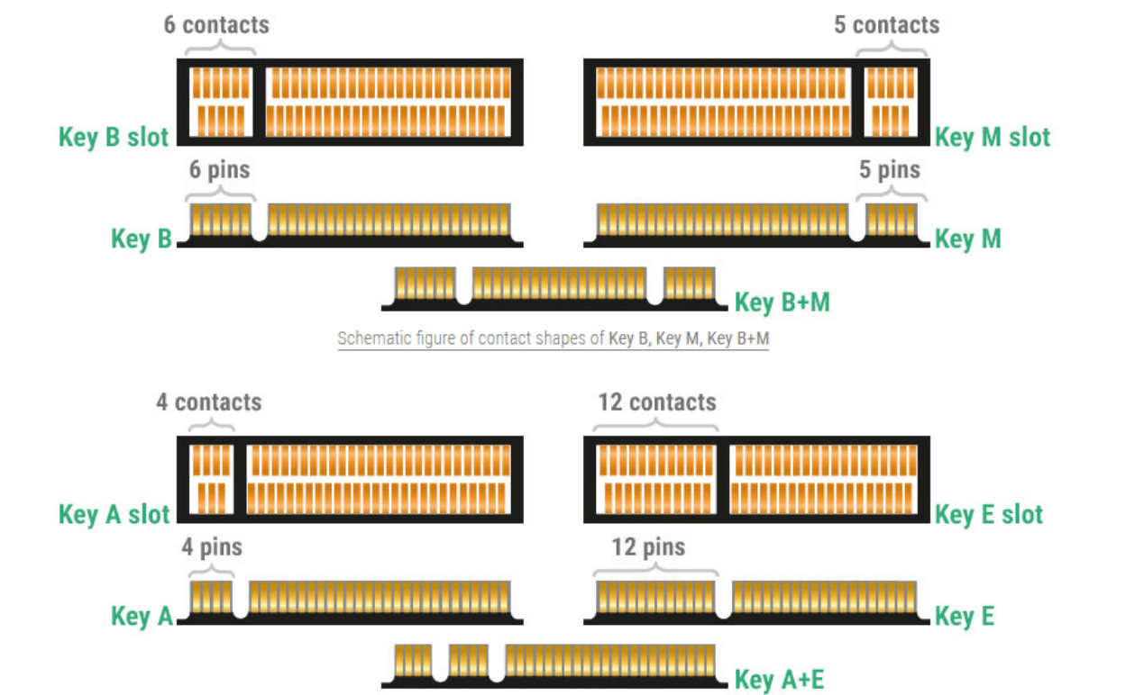
Original English figure — 102
14.8 Board-Level Configurable Timing
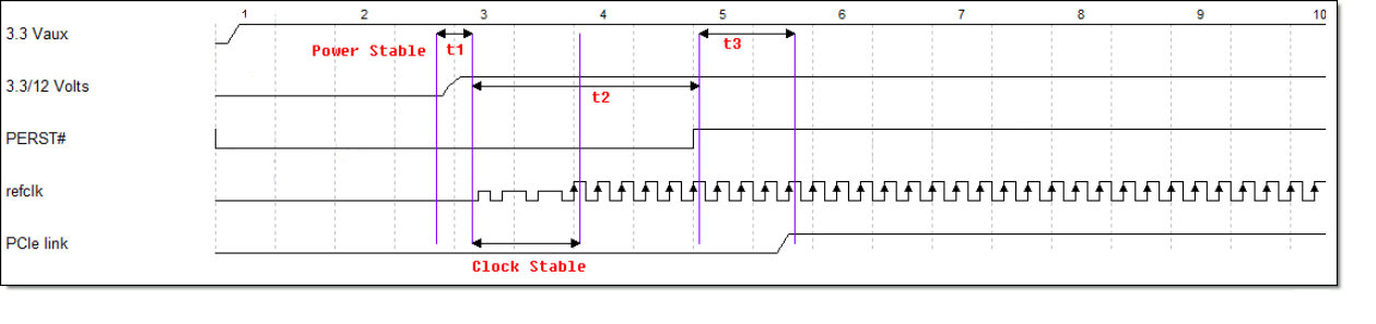
Original English figure — 102
| Adjustable Time | Icon | DTS Property | Description (Linux Kernel Phase) |
|---|---|---|---|
| Power Stable | t1 | startup-delay-us | This property is configured in the power node referenced by the vpcie3v3-supply of the PCIe node. |
| Tpvperl | t2 | rockchip,perst-inactive-ms | This property is configured in the PCIe node. If not configured, it defaults to 200ms and takes effect at boot time. |
| Tpvperl | t2 | rockchip,s2r-perst-inactive-ms | This property is configured in the PCIe node. If not configured, it defaults to the same value as rockchip,perst-inactive-ms, and takes effect when resuming from hibernation. |
| Out of Electrical Idle | t3 | rockchip,wait-for-link-ms | This property is configured in the PCIe node. If not configured, it defaults to 1ms and is used to wait for the link to be initiated each time. |
14.9 RK3568 PCIe30PHY SRNS Patch
diff --git a/drivers/phy/rockchip/phy-rockchip-snps-pcie3.c b/drivers/phy/rockchip/phy-rockchip-snps-pcie3.c
index 2392bcb..fa3244e 100644
--- a/drivers/phy/rockchip/phy-rockchip-snps-pcie3.c
+++ b/drivers/phy/rockchip/phy-rockchip-snps-pcie3.c
@@ -19,12 +19,15 @@
 #include <dt-bindings/phy/phy.h>

 #define GRF_PCIE30PHY_CON4 0x10
+#define GRF_PCIE30PHY_CON5 0x14
 #define GRF_PCIE30PHY_CON6 0x18

@@ -97,6 +100,17 @@
                 (0x1 << 15) | (0x1 << 31));
    }

+
+   /* rx0_cmn_refclk_mode disabled */
+   regmap_write(priv->phy_grf, GRF_PCIE30PHY_CON5, (0x0) | (0x1 << 25));
+   /* rx1_cmn_refclk_mode disabled */
+   regmap_write(priv->phy_grf, GRF_PCIE30PHY_CON6, (0x0) | (0x1 << 25));
+
    regmap_write(priv->phy_grf, GRF_PCIE30PHY_CON4,
             (0x0 << 14) | (0x1 << (14 + 16))); //sdram_ld_done
    regmap_write(priv->phy_grf, GRF_PCIE30PHY_CON4,