
This platform reference preserves the complete technical body of the 436-page English V1.2.5 source (PDF pp.16–436), including the RK-RAW formats and the final error-code and abbreviation chapters. No corresponding Chinese PDF was supplied. Chinese and Russian are full translations of this English version; all 42 original technical figures come from the English PDF, including Chinese labels already present there. Ten image-based RAW layout/format tables are additionally transcribed as editable tables. No whole-page images replace the body.
The source specifies RK3588 / Linux 5.10, with BuildRoot and Android marked Y and Debian and Yocto marked N. These are historical source records, not a promise of support in every BSP. For ArmSoM boards, verify the exact SoC, ISP generation, sensor/VCM, kernel, AIQ library, IQ file and SDK/BSP branch first. ArmSoM Sige7 is an RK3588 board, but this article’s APIs and examples have not been validated on its hardware. All measurements and examples belong to the source; no hardware commands or camera/motor operations were executed.
Source issues: repeated API headings, mixed ISP generations and types, conflicting units, defaults, log levels and RAW field descriptions are retained and listed in the editorial notes. Values and identifiers are not silently corrected. Code comments remain in their original language. Commands and APIs can alter camera or motor state; adapt and review before use.
EDITORIAL-NOTES · ArmSoM Sige7 · ArmSoM camera documentation · Rockchip Linux
1. General overview
1.1 Structure diagram
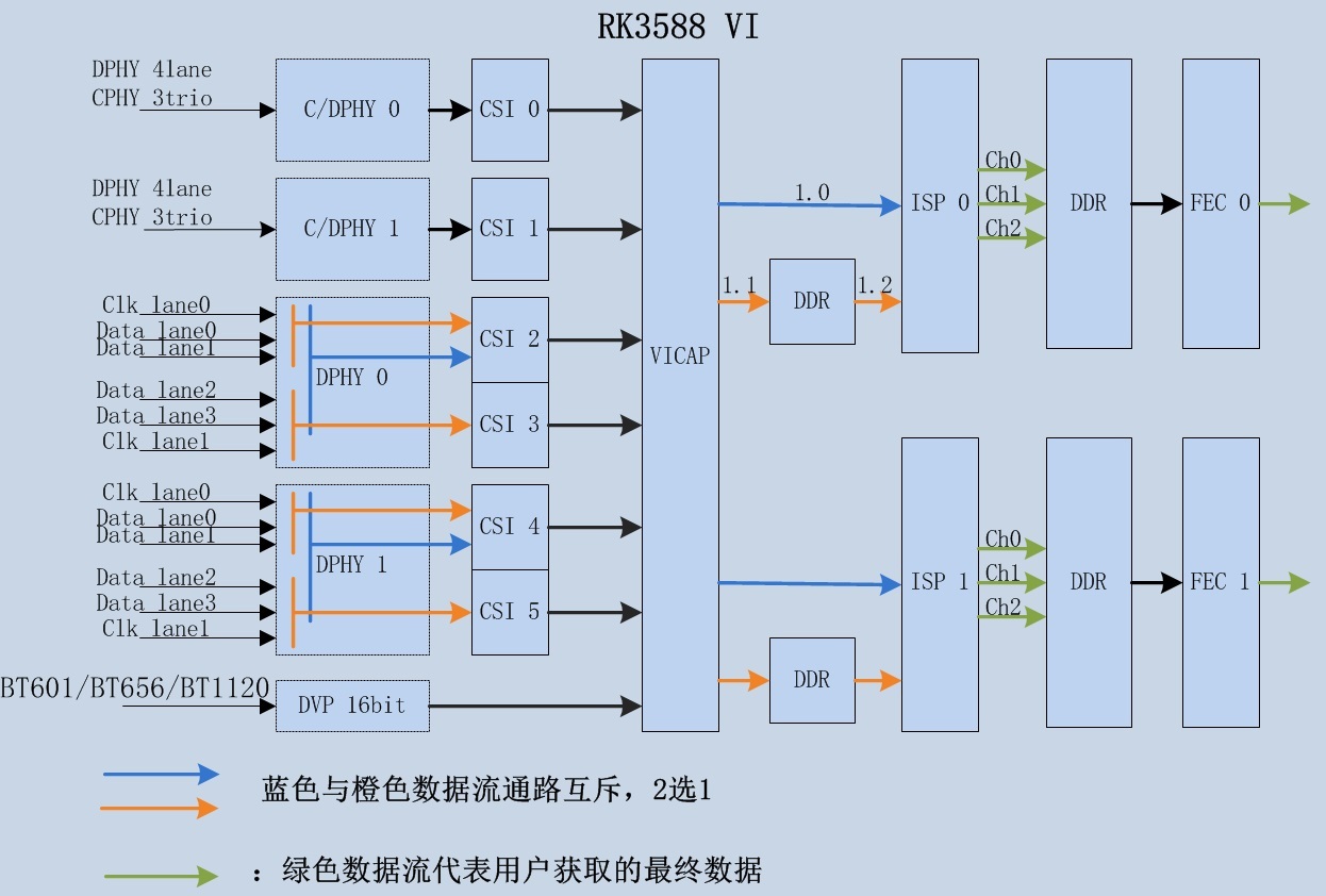
RK3588 VI as a general term for video input modules, contains:
Interface and data acquisition part: C/DPHY, DVP, CSI, VICAP
Image processing part: ISP-0,ISP-1,FEC-0,FEC-1
The RK3588 ISP belongs to the RK ISP v3.0 version, and subsequent documents are identified as ISP30.
1.2 mode of operation
Single ISP Single CIS (CMOS Image Sensor):
RAW pass-through/online mode: The blue arrows in the block diagram indicate the data flow 1.0 path
Raw readback/offline mode: Orange arrows in the block diagram indicate traffic 1.1, 1.2 paths
Dual ISP 2-in-1 mode for single CIS:
The 2-in-1 mode supports ISP-0/ISP-1 to process the left and right parts of a single CIS image separately to support large resolution CIS.
Multi-CIS :
Single ISP adopts Raw readback/offline mode, which can support multi-CIS input in time-division multiplexing.
1.3 Overview of performance and constraints
Supported resolutions and throughput:
| Working mode | Throughput | Maximum resolution |
Minimum resolution supported |
|---|---|---|---|
| Single ISP Single CIS | 16Mega@30fps | 4672x3504 | 208x128 |
| Dual ISP 2-in-1 Single CIS |
32Mega@30fps | 8064x6048 | \ |
Support Raw12 data entry.
ISP30 supports processing Raw12 data. The Raw14 data input discards the low bits for Raw12 processing. Image data input with a bit width of less than 12 bits will supplement the low bit to Raw12 processing.
Support for Bayer color CIS, Mono CIS.
Support 3-in-1 multi-frame HDR. The following types of HDR CIS are supported:
| Multi exposure HDR | RK Platform support | CIS | Apply |
|---|---|---|---|
| Sequential / Framebase HDR | ISP20: RV1109/RV1126 etc ISP21: RK356X etc ISP30: RK3588 ISP32: RV1106 |
OV4689 | IPC/CVR |
| Staggered / DOL HDR | ISP20: RV1109/RV1126 etc ISP21: RK356X etc ISP30: RK3588 ISP32: RV1106 |
OS04A10 IMX464 AR0239 |
IPC/CVR |
| DCG HDR | ISP20: RV1109/RV1126 etc ISP21: RK356X etc ISP30: RK3588 ISP32: RV1106 |
OS04A10 IMX585 |
IPC/CVR |
| SME HDR | N | IMX378 | Consumer |
| BME HDR | N | IMX258 | Consumer |
| QBC HDR | N | OV50C40 IMX586 |
Consumer |
| Lateral overflow HDR | N | AR0821 | IPC |
| Splite-diode pixel HDR | N | OV10640 | CVR |
Lowest latency for ISP30 data output to DDR notification stage in Raw pass-through/online mode: approx. image frame transmission time/15.
In ISP time-division multiplexing mode, a single ISP supports up to four data source inputs.
In RAW pass-through/online mode, the minimum image frame is blanked by 136 lines and the minimum image line is blanked by 16 pixels
The CSM module does not support YUV limit range conversion, see the IMGPROC/CSM module API description for details
2. Overview
ISP30 includes a series of image processing algorithm modules, mainly including: dark current correction, dead pixel correction, 3A, HDR, lens shadow correction, lens distortion correction, 3DLUT, denoising (including RAW domain denoising, multi-frame noise reduction, color denoising, etc.), sharpening, etc.
ISP30 includes hardware algorithm implementation and software logic control part, RkAiq is the implementation of software logic control part.
The main functions of the RkAiq software module are: to obtain image statistics from the ISP driver, combine IQ Tuning parameters, use a series of algorithms to calculate new ISP, Sensor and other hardware parameters, and continuously iterate the process to finally achieve the best image effect.
2.1 Feature description
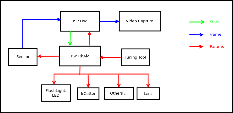
Figure 1-1 ISP21 system block diagram
The overall software and hardware block diagram of ISP30 is shown in Figure 1-1. The sensor outputs a data stream to the ISP HW, WHICH IN TURN OUTPUTS THE IMAGE AFTER A SERIES OF IMAGE PROCESSING ALGORITHMS. RkAiq continuously obtains statistical data from ISP HW, and generates new parameters through algorithms such as 3A to feed back to each hardware module. Tuning tool can debug parameters online in real time, and after debugging, a new IQ parameter file can be saved and generated.
2.2 RkAiq architecture
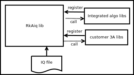
Figure 1-2 Overall architecture diagram of RkAiq
1. The ISP30 RkAiq software design idea is shown in Figure 1-2. It is mainly divided into the following four parts:
1. RkAiq lib dynamic library. The library contains the main logical part, which is responsible for obtaining statistics from the driver and passing them to the individual algorithm libraries.
2. Integrated algo libs。 The static algorithm library provided by Rk is registered with the RkAiq lib dynamic library by default.
3. customer 3A libs。 Customers can implement their own 3A algorithm library or other algorithm libraries according to the algorithm library interface definition. After you register a custom algorithm library with the RkAiq lib dynamic library, you can choose whether to run the custom library or the Rk library according to the provided interface.
4. IQ file。 IQ tuning result files store algorithm-related parameters and some system static parameters such as CIS.
2.3 Software architecture
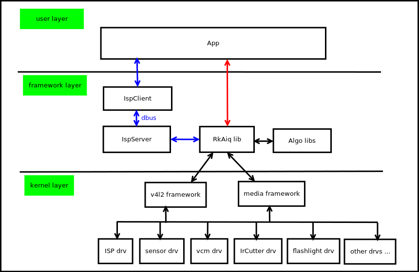
Figure 1-3 Block diagram of software architecture
The ISP30 software block diagram is shown in Figure 1-3. It is mainly divided into the following three layers:
1. kernel layer。 This layer contains all hardware drivers for the camera system, mainly ISP drivers, sensor drivers, VCM drivers, flashlight drivers, IrCutter drivers and so on. The drivers are based on V4L2 and the Media framework.
2. framework layer。 This layer is the integration layer of RkAiq lib, which has two integration methods:
IspServer mode In this way, the Rkaiq lib runs on the IspServer standalone process, with which the client communicates via dbus. In addition, this method can provide images with ISP debugging effect for existing third-party applications such as v4L-CTL without modifying the source code.
Direct integration RkAiq lib can be integrated directly into applications.
3. user layer. User application layer.
2.4 Software processes
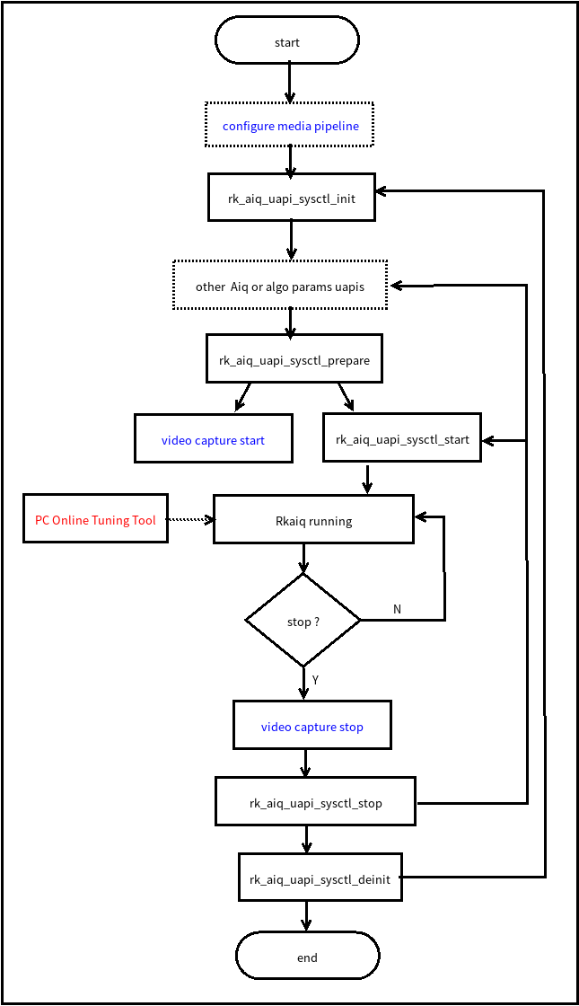
Figure 1-4 Flow chart
The RkAiq interface call process is shown in Figure 1-4. The dotted box part in the figure is optional, and the blue font part is the configuration that the application needs to use with the RkAiq process.
configure media pipeline。 Optionally, configure the ISP30 pipeline, such as sensor output resolution, etc., the driver has a default configuration. rk_aiq_uapi2_sysctl_init。 Initialize RkAiq, including IQ tuning parameters and initialization of various algorithm libraries. other Aiq or algo params uapis。 Optionally, you can configure the required parameters through the API interface provided by each algorithm, and register third-party algorithm libraries. rk_aiq_uapi2_sysctl_prepare。 Prepare the initialization parameters of each algorithm library and each hardware module, and set them to the driver.
video capture start。 This process is enabled for the application ISP traffic, and the process needs to be called after rk_aiq_uapi2_sysctl_prepare.
rk_aiq_uapi2_sysctl_start。 Start the RkAiq internal flow, after the interface call is successful, the sensor starts to output data, the ISP starts processing data, and outputs the processed image.
Rkaiq running。 RkAiq continuously obtains statistics from the ISP driver, calls algorithms such as 3A to calculate new parameters, and applies new parameters to the driver. PC Online Tuning Tool。 The PC can adjust the parameters online via the Tuning Tool. video capture stop。 Before stopping the RkAiq process, you need to stop the data flow section. rk_aiq_uapi2_sysctl_stop。 Stop the RkAiq running process. You can adjust the parameters and start it again or start it directly.
rk_aiq_uapi2_sysctl_deinit。 Deinitialize RkAiq.
2.5 API description
The APIs provided by RKAiq are divided into two levels: functional-level APIs and module-level APIs.
Functional level API: Based on module-level API packaging, mainly for product applications based on some simple functional design of the module.
Module-level API: Detailed parameter settings and queries for this module, without API differentiation of functions.
The module-level APIs provided by RKAiq support synchronous and asynchronous modes, and functional- level APIs are encapsulated by default in the synchronous mode of module-level APIs.
Sync mode: This mode is a blocking API, AIQ basically updates parameters with video frames as granularity, and in synchronous mode, the time that the thread calling the API may be blocked <= video frame cycle time.
Asynchronous Mode (ASync): This mode is a non-blocking API, the AIQ framework will store API setting parameters in the internal parameter buffer, and set the latest ISP parameter setting to the hardware at the time.
Instructions for using the synchronous asynchronous mode of module-level APIs
The second parameter structure of the module-level API is generally a collection of setting parameters, called a property structure. The internal rk_aiq_uapi_sync_t members of the structure can configure the call mode of the current API, referring to the following data types for details:
2.5.1 rk_aiq_uapi_sync_t
【Description】 Module sync mode
【Definition】
 typedef struct rk_aiq_uapi_sync_s {
     rk_aiq_uapi_mode_sync_e     sync_mode;
     bool                        done;
 } rk_aiq_uapi_sync_t;
【Member】
| Member Name |
Description |
|---|---|
| sync_mode | @setAttrib: Flag for parameter update mode; RK_AIQ_UAPI_MODE_DEFAULT: The default is synchronous mode. RK_AIQ_UAPI_MODE_SYNC: Synchronous mode. RK_AIQ_UAPI_MODE_ASYNC: Asynchronous mode. @getAttrib: RK_AIQ_UAPI_MODE_DEFAULT: Get last set property by default (sync_mode == RK_AIQ_UAPI_MODE_ASYNC), may not take effect yet RK_AIQ_UAPI_MODE_SYNC: Get the currently used properties. RK_AIQ_UAPI_MODE_ASYNC: Same as RK_AIQ_UAPI_MODE_DEFAULT. |
| done | @done (parsm out): Flag for parameter update status, true for parameter update, false for parameter not updated. |
The AIQ API reference code is divided into modules, and API examples are provided separately, which is recommended for customers to refer to directly
rkisp_demo/demo/sample
| Filename | Module |
|---|---|
| sample_3dlut_module.cpp | 3DLUT |
| sample_ccm_module.cpp | CCM |
| sample_csm_module.cpp | CSM |
| sample_ablc_module.cpp | BLC |
| sample_abayer2dnr_module.cpp | BayerNR 2D |
| sample_abayertnr_module.cpp | BayerNR 3D |
| sample_aynr_module.cpp | YNR |
| sample_acnr_module.cpp | CNR |
| sample_asharp_module.cpp | Sharp |
| sample_amerge_module.cpp | Merge(HDR) |
| sample_adrc_module.cpp | DRC |
| sample_adehaze_module.cpp | Dehaze & Enhance |
| sample_agamma_module.cpp | Gamma |
| sample_awb_module.cpp | AWB |
| sample_ae_module.cpp | AE |
| sample_af_module.cpp | AF |
3. System control
3.1 Feature overview
The system control section contains AIQ public attribute configuration, initializing AIQ, running AIQ, exiting AIQ, setting AIQ modules and other functions.
3.2 API Reference
3.2.1 rk_aiq_uapi2_sysctl_preInit
【Description】 Before initializing AIQ, preset some parameters, such as the IQ file used.
【Grammar】
 XCamReturn
 rk_aiq_uapi2_sysctl_preInit (const char* sns_ent_name,
                          rk_aiq_working_mode_t mode,
                          const char* force_iq_file);
【Parameters】
| Parameter Name | Description | Input/Output |
|---|---|---|
| sns_ent_name | sensor entity name | Input |
| mode | ISP mode of operation | Input |
| force_iq_file | Mandatory iq file | Input |
【Return Value】
| Return value | Description |
|---|---|
| 0 | Success |
| Non-0 | Failure, see Error Code Table |
【Requirements】
Header file: rk_aiq_user_api2_sysctl.h
Library file: librkaiq.so
【Note】
Should precede rk_aiq_uapi2_sysctl_init call
The parameter mode is only used to select IQ files, and does not configure the ISP operating mode, which needs to be configured in rk_aiq_uapi2_sysctl_prepare. If the parameter force_iq_file is not empty, the mode parameter is invalid
Parameter force_iq_file is the full path
This function is not required and is only used to change some default settings before rk_aiq_uapi2_sysctl_init
3.2.2 rk_aiq_uapi2_sysctl_preInit_scene
【Description】 Before initializing AIQ, select IQ Scenario Parameters.
【Grammar】
 XCamReturn
 rk_aiq_uapi2_sysctl_preInit_scene (const char* sns_ent_name,
                          const char *main_scene,
                         const char *sub_scene);
【Parameters】
| Parameter Name | Description | Input/Output |
|---|---|---|
| sns_ent_name | sensor entity name | Input |
| main_scene | For the main scene, the values are defined in the IQ file | Input |
| sub_scene | For subscenarios, the values are defined in the IQ file | Input |
【Return Value】
| Return value | Description |
|---|---|
| 0 | Success |
| Non-0 | Failure, see Error Code Table |
【Requirements】
Header file: rk_aiq_user_api2_sysctl.h
Library file: librkaiq.so
【Note】
Should precede rk_aiq_uapi2_sysctl_init call
main_scene needs to be selected according to the main scene array in the IQ file, the default is generally “normal”
sub_scene needs to be selected according to the sub-scene array in the main scene in the IQ file, the default is generally “day”
Since the default selected scene is normal-day, if you want to run hdr-day, or other custom modes, You need to call this function to specify, otherwise the IQ parameter may be incorrect
3.2.3 rk_aiq_uapi2_sysctl_switch_scene
【Description】 After initializing AIQ, switch the IQ scenario parameters.
【Grammar】
 int
 rk_aiq_uapi2_sysctl_switch_scene (const rk_aiq_sys_ctx_t* sys_ctx,
                          const char *main_scene,
                         const char *sub_scene);
【Parameters】
| Parameter Name | Description | Input/Output |
|---|---|---|
| sys_ctx | AIQ context pointer | Input |
| main_scene | For the main scene, the values are defined in the IQ file | Input |
| sub_scene | For subscenarios, the values are defined in the IQ file | Input |
【Return Value】
| Return value | Description |
|---|---|
| 0 | Success |
| Non-0 | Failure, see Error Code Table |
【Requirements】
Header file: rk_aiq_user_api2_sysctl.h
Library file: librkaiq.so
【Note】
Called after rk_aiq_uapi2_sysctl_init
main_scene needs to be selected based on the array of main scenes in the IQ file
sub_scene needs to be selected based on the array of subscenes in the main scene in the IQ file
This interface involves IQ dynamic switching, which is currently inadequately tested and may cause unexpected results, so use with caution
3.2.4 rk_aiq_uapi2_sysctl_init
【Description】 Initialize the AIQ context.
【Grammar】
 rk_aiq_sys_ctx_t*
 rk_aiq_uapi2_sysctl_init (const char* sns_ent_name,
                          const char* iq_file_dir,
                          rk_aiq_error_cb err_cb,
                          rk_aiq_metas_cb metas_cb);
【Parameters】
| Parameter Name | Description | Input/Output |
|---|---|---|
| sns_ent_name | sensor entity name | Input |
| iq_file_dir | Calibration parameter file path | Input |
| err_cb | Error callback function, which can be NULL | Input |
| metas_cb | The meta data callback function, which can be NULL | Input |
【Return Value】
| Return value | Description |
|---|---|
| rk_aiq_sys_ctx_t* | AIQ context pointer |
【Requirements】
Header file: rk_aiq_user_api2_sysctl.h
Library file: librkaiq.so
【Note】
Should precede other function calls.
3.2.5 rk_aiq_uapi2_sysctl_deinit
【Description】 Deinitialize the AIQ context.
【Grammar】
 void
 rk_aiq_uapi2_sysctl_deinit( rk_aiq_sys_ctx_t* ctx);
【Parameters】
| Parameter Name | Description | Input/Output |
|---|---|---|
| ctx | AIQ context pointer | Input |
【Return Value】
| Return value | Description |
|---|---|
| None | None |
【Requirements】
Header file: rk_aiq_user_api2_sysctl.h
Library file: librkaiq.so
【Note】
Should not be called when AIQ is in the start state.
3.2.6 rk_aiq_uapi2_sysctl_prepare
【Description】 Prepare the AIQ operating environment.
【Grammar】
 XCamReturn
 rk_aiq_uapi2_sysctl_prepare(const rk_aiq_sys_ctx_t* ctx,
                            uint32_t  width,
                            uint32_t  height,
                            rk_aiq_working_mode_t mode);
【Parameters】
| Parameter Name |
Description | Input/Output |
|---|---|---|
| ctx | AIQ context pointer | Input |
| width | The resolution width of the sensor output, which is used only for verification |
Input |
| height | The resolution height of the sensor output, which is only used for verification |
Input |
| mode | ISP Pipeline mode of operation (NORMAL/HDR) | Input |
【Return Value】
| Return value | Description |
|---|---|
| 0 | Success |
| Non-0 | Failure, see Error Code Table |
【Requirements】
Header file: rk_aiq_user_api2_sysctl.h
Library file: librkaiq.so
【Note】
Should be called before rk_aiq_uapi2_sysctl_start function.
If you need to call this function after the rk_aiq_uapi2_sysctl_start, call the rk_aiq_uapi2_sysctl_stop function first, and then call rk_aiq_uapi2_sysctl_prepare to reprepare the running environment.
3.2.7 rk_aiq_uapi2_sysctl_start
【Description】 Start the AIQ control system. After AIQ is started, it will continuously obtain 3A statistics from the ISP driver, run the 3A algorithm, and apply the calculated new parameters.
【Grammar】
 XCamReturn
 rk_aiq_uapi2_sysctl_start(const rk_aiq_sys_ctx_t* ctx);
【Parameters】
| Parameter Name | Description | Input/Output |
|---|---|---|
| ctx | AIQ context pointer | Input |
【Return Value】
| Return value | Description |
|---|---|
| 0 | Success |
| Non-0 | Failure, see Error Code Table |
【Requirements】
Header file: rk_aiq_user_api2_sysctl.h
Library file: librkaiq.so
【Note】
Should be called after the rk_aiq_uapi2_sysctl_prepare function.
3.2.8 rk_aiq_uapi2_sysctl_stop
【Description】 Stop the AIQ control system.
【Grammar】
 XCamReturn
 rk_aiq_uapi2_sysctl_stop(const rk_aiq_sys_ctx_t* ctx, bool keep_ext_hw_st);
【Parameters】
| Parameter Name |
Description | Input/Output |
|---|---|---|
| ctx | AIQ context pointer | Input |
| keep_ext_hw_st | After stop, whether the state of the external device such as (ircut/cpsl) remains unchanged |
Input |
【Return Value】
| Return value | Description |
|---|---|
| 0 | Success |
| Non-0 | Failure, see Error Code Table |
【Requirements】
Header file: rk_aiq_user_api2_sysctl.h
Library file: librkaiq.so
3.2.9 rk_aiq_uapi2_sysctl_getStaticMetas
【Description】 Query sensor corresponds to static information such as resolution, data format, etc.
【Grammar】
 XCamReturn
 rk_aiq_uapi2_sysctl_getStaticMetas(const char* sns_ent_name,
 rk_aiq_static_info_t* static_info);
【Parameters】
| Parameter Name | Description | Input/Output |
|---|---|---|
| sns_ent_name | sensor entity name | Input |
| static_info | Static information struct pointer | Output |
【Return Value】
| Return value | Description |
|---|---|
| 0 | Success |
| Non-0 | Failure, see Error Code Table |
【Requirements】
Header file: rk_aiq_user_api2_sysctl.h
Library file: librkaiq.so
3.2.10 rk_aiq_uapi2_sysctl_enumStaticMetas
【Description】 Enumerates the static information obtained by AIQ.
【Grammar】
 XCamReturn
 rk_aiq_uapi2_sysctl_enumStaticMetas(int index, rk_aiq_static_info_t*
 static_info);
【Parameters】
| Parameter Name | Description | Input/Output |
|---|---|---|
| index | Index number, starting from 0 | Input |
| static_info | Static information struct pointer | Output |
【Return Value】
| Return value | Description |
|---|---|
| 0 | Success |
| Non-0 | Failure, see Error Code Table |
【Requirements】
Header file: rk_aiq_user_api2_sysctl.h
Library file: librkaiq.so
3.2.11 rk_aiq_uapi2_sysctl_enableAxlib
【Description】 Set the custom algorithm library running status.
【Grammar】
 XCamReturn
 rk_aiq_uapi2_sysctl_enableAxlib(const rk_aiq_sys_ctx_t* ctx,
                                const int algo_type,
                                const int lib_id,
                                bool enable);
【Parameters】
| Parameter Name | Description | Input/Output |
|---|---|---|
| ctx | AIQ context pointer | Input |
| algo_type | The type of algorithm module to operate with | Input |
| lib_id | Algorithm library identification ID | Input |
| enable | Status Settings | Input |
【Return Value】
| Return value | Description |
|---|---|
| 0 | Success |
| Non-0 | Failure, see Error Code Table |
【Requirements】
Header file: rk_aiq_user_api2_sysctl.h
Library file: librkaiq.so
【Note】
If the lib_id is equivalent to the currently running algorithm library, this function can be called in any state except uninitialized.
In other cases, it is only called in the prepared state, and the algorithm library identified by the algo_type will be replaced by the new algorithm library identified by lib_id.
3.2.12 rk_aiq_uapi2_sysctl_getAxlibStatus
【Description】 Gets the algorithm library status.
【Grammar】
 bool
 rk_aiq_uapi2_sysctl_getAxlibStatus(const rk_aiq_sys_ctx_t* ctx,
                                   const int algo_type,
                                   const int lib_id);
【Parameters】
| Parameter Name | Description | Input/Output |
|---|---|---|
| ctx | AIQ context pointer | Input |
| algo_type | The type of algorithm module to operate with | Input |
| lib_id | Algorithm library identification ID | Input |
【Return Value】
| Return value | Description |
|---|---|
| false | Shutdown Status |
| true | Enable Status |
【Requirements】
Header file: rk_aiq_user_api2_sysctl.h
Library file: librkaiq.so
3.2.13 rk_aiq_uapi2_sysctl_getEnabledAxlibCtx
【Description】 Gets the context structure of the enable algorithm library.
【Grammar】
 const RkAiqAlgoContext*
 rk_aiq_uapi2_sysctl_getEnabledAxlibCtx(const rk_aiq_sys_ctx_t* ctx, const int
 algo_type);
【Parameters】
| Parameter Name | Description | Input/Output |
|---|---|---|
| ctx | AIQ context pointer | Input |
| algo_type | The type of algorithm module to operate with | Input |
【Return Value】
| Return value | Description |
|---|---|
| NULL | Get failed |
| Non-NULL | Get Success |
【Requirements】
Header file: rk_aiq_user_api2_sysctl.h
Library file: librkaiq.so
【Note】
The returned algorithm context struct will be used by the internal private function. For user-defined algorithm libraries, the function should be called after the rk_aiq_uapi2_sysctl_enableAxlib, otherwise NULL will be returned.
3.2.14 rk_aiq_uapi2_sysctl_setCpsLtCfg
【Description】 Set fill light control information.
【Grammar】
 XCamReturn
 rk_aiq_uapi2_sysctl_setCpsLtCfg(const rk_aiq_sys_ctx_t* ctx,
                        rk_aiq_cpsl_cfg_t* cfg);
【Parameters】
| Parameter Name | Description | Input/Output |
|---|---|---|
| ctx | AIQ context pointer | Input |
| cfg | Fill light configuration structure pointer | Input |
【Return Value】
| Return value | Description |
|---|---|
| 0 | Success |
| Non-0 | Failure, see Error Code Table |
【Requirements】
Header file: rk_aiq_user_api2_sysctl.h
Library file: librkaiq.so
3.2.15 rk_aiq_uapi2_sysctl_getCpsLtInfo
【Description】 Get fill light control information.
【Grammar】
 XCamReturn
 rk_aiq_uapi2_sysctl_getCpsLtInfo(const rk_aiq_sys_ctx_t* ctx,
                        rk_aiq_cpsl_info_t* info);
【Parameters】
| Parameter Name | Description | Input/Output |
|---|---|---|
| ctx | AIQ context pointer | Input |
| info | Fill light configuration structure pointer | Output |
【Return Value】
| Return value | Description |
|---|---|
| 0 | Success |
| Non-0 | Failure, see Error Code Table |
【Requirements】
Header file: rk_aiq_user_api2_sysctl.h
Library file: librkaiq.so
3.2.16 rk_aiq_uapi2_sysctl_queryCpsLtCap
【Description】 Check the support capabilities of fill lights.
【Grammar】
 XCamReturn
 rk_aiq_uapi2_sysctl_queryCpsLtCap(const rk_aiq_sys_ctx_t* ctx,
                        rk_aiq_cpsl_cap_t* cap);
【Parameters】
| Parameter Name | Description | Input/Output |
|---|---|---|
| ctx | AIQ context pointer | Input |
| cap | The fill light supports the ability to query the structure pointer | Output |
【Return Value】
| Return value | Description |
|---|---|
| 0 | Success |
| Non-0 | Failure, see Error Code Table |
【Requirements】
Header file: rk_aiq_user_api2_sysctl.h
Library file: librkaiq.so
3.2.17 rk_aiq_uapi2_sysctl_getBindedSnsEntNmByVd
【Description】 Query the sensor entity name corresponding to the video node.
【Grammar】
const char* rk_aiq_uapi2_sysctl_getBindedSnsEntNmByVd(const char* vd);
【Parameters】
| Parameter Name | Description | Input/Output |
|---|---|---|
| vd | Video path, such as /dev/video20 | Input |
【Return Value】
| Return value | Description |
|---|---|
| sensor entity name | String pointer |
【Note】
The parameter must be the ISPP scale node path.
【Requirements】
Header file: rk_aiq_user_api2_sysctl.h
Library file: librkaiq.so
3.2.18 rk_aiq_uapi2_sysctl_updateIq
【Description】 Dynamically update the currently used IQ parameter file without stopping the data flow.
【Grammar】
 XCamReturn rk_aiq_uapi2_sysctl_updateIq(const rk_aiq_sys_ctx_t* sys_ctx, char*
 iqfile);
【Parameters】
| Parameter Name | Description | Input/Output |
|---|---|---|
| ctx | AIQ context pointer | Input |
| iqfile | New IQ file | Input |
【Return Value】
| Return value | Description |
|---|---|
| 0 | Success |
| Non-0 | Failure, see Error Code Table |
【Note】
iqfile needs to be a full path.
Updating IQ parameters does not mean that the operating mode can be switched, such as switching HDR and normal, can not be updated IQ file implementation; However, the switching of some functions can be achieved through different configurations of IQ parameters, such as day and night switching Switching is achieved entirely through IQ configuration.
When switching IQ, the configuration parameters in IQ will override the settings of the user API. For example, AWB module can be configured manually and automatically in IQ mode, then after executing this function, no matter what mode the current AWB is in, it will eventually be overwritten by the default configuration in the new IQ.
【Requirements】
Header file: rk_aiq_user_api2_sysctl.h
Library file: librkaiq.so
3.2.19 rk_aiq_uapi2_sysctl_getCrop
【Description】 Get the crop parameter.
【Grammar】
 XCamReturn
 rk_aiq_uapi2_sysctl_getCrop(const rk_aiq_sys_ctx_t* sys_ctx, rk_aiq_rect_t
 *rect);
【Parameters】
| Parameter Name | Description | Input/Output |
|---|---|---|
| sys_ctx | AIQ context pointer | Input |
| rect | crop parameter struct pointer | Output |
【Return Value】
| Return value | Description |
|---|---|
| 0 | Success |
| Non-0 | Failure, see Error Code Table |
3.3 Data type
3.3.1 rk_aiq_working_mode_t
【Description】 AIQ pipeline working mode
【Definition】
 typedef enum {
     RK_AIQ_WORKING_MODE_NORMAL,
     RK_AIQ_WORKING_MODE_ISP_HDR2    = 0x10,
     RK_AIQ_WORKING_MODE_ISP_HDR3    = 0x20,
 } rk_aiq_working_mode_t;
【Member】
| Member Name | Description |
|---|---|
| RK_AIQ_WORKING_MODE_NORMAL | Normal mode |
| RK_AIQ_WORKING_MODE_ISP_HDR2 | Two-frame HDR mode |
| RK_AIQ_WORKING_MODE_ISP_HDR3 | Three-frame HDR mode |
【Precautions】
You need to query the mode supported by sensor and AIQ first, if the set mode is not supported, the setting is invalid.
3.3.2 rk_aiq_static_info_t
【Description】 AIQ static information
【Definition】
 typedef struct {
     rk_aiq_sensor_info_t    sensor_info;
     rk_aiq_lens_info_t      lens_info;
     bool has_lens_vcm;
     bool has_fl;
     bool fl_strth_adj_sup;
     bool has_irc;
     bool fl_ir_strth_adj_sup;
 } rk_aiq_static_info_t;
【Member】
| Member Name | Description |
|---|---|
| sensor_info | Description of the sensor’s name, supported resolutions, etc. |
| lens_info | Lens information |
| has_lens_vcm | With or without VCM |
| has_fl | With flash |
| fl_strth_adj_sup | With flash adjustable |
| bool has_irc | With IR-CUT |
| bool fl_ir_strth_adj_sup |
3.3.3 rk_aiq_sensor_info_t
【Description】 Sensor information
【Definition】
 typedef struct {
     char sensor_name[32];
     rk_frame_fmt_t  support_fmt[SUPPORT_FMT_MAX];
     int32_t num;
     /* binded pp stream media index */
     int8_t binded_strm_media_idx;
 } rk_aiq_sensor_info_t;
【Member】
| Member Name | Description |
|---|---|
| sensor_name | Name of the sensor |
| support_fmt | Supported formats |
| num | Number of supported formats |
| has_fl | With flash |
| binded_strm_media_idx | The media node number on which the sensor is mounted |
3.3.4 rk_aiq_module_id_t
【Description】 AIQ module ID
【Definition】
 typedef enum {
     RK_MODULE_INVAL = 0,
     RK_MODULE_DPCC,
     RK_MODULE_BLS,
     RK_MODULE_LSC,
     RK_MODULE_AWB_GAIN,
     RK_MODULE_CTK,
     RK_MODULE_GOC,
     RK_MODULE_SHARP,
     RK_MODULE_AE,
     RK_MODULE_AWB,
     RK_MODULE_NR,
     RK_MODULE_GIC,
     RK_MODULE_3DLUT,
     RK_MODULE_LDCH,
     RK_MODULE_TNR,
     RK_MODULE_FEC,
     RK_MODULE_MAX
 }rk_aiq_module_id_t;
【Member】
| Member Name | Description |
|---|---|
| RK_MODULE_DPCC | Dead pixel detection and correction |
| RK_MODULE_BLS | Black level |
| RK_MODULE_LSC | Lens shadow correction |
| RK_MODULE_AWB_GAIN | White balance gain |
| RK_MODULE_CTK | Color correction |
| RK_MODULE_GOC | Gamma |
| RK_MODULE_SHARP | Sharpen |
| RK_MODULE_AE | Exposure |
| RK_MODULE_AWB | White balance |
| RK_MODULE_NR | Denoising |
| RK_MODULE_GIC | Green Balance |
| RK_MODULE_3DLUT | 3DLUT |
| RK_MODULE_LDCH | LDCH |
| RK_MODULE_TNR | 3D denoising |
| RK_MODULE_FEC | Fisheye correction |
3.3.5 rk_aiq_cpsl_cfg_t
【Description】 The fill light sets the information structure
【Definition】
 typedef struct rk_aiq_cpsl_cfg_s {
     RKAiqOPMode_t mode;
     rk_aiq_cpsls_t lght_src;
     bool gray_on; /*!< force to gray if light on */
     union {
         struct {
             float sensitivity; /*!< Range [0-100] */
             uint32_t sw_interval; /*!< switch interval time, unit  seconds */
         } a; /*< auto mode */
         struct {
             uint8_t on; /*!< disable 0, enable 1 */
             float strength_led; /*!< Range [0-100] */
             float strength_ir; /*!< Range [0-100] */
         } m; /*!< manual mode */
     } u;
 } rk_aiq_cpsl_cfg_t;
【Member】
| Member Name | Description |
|---|---|
| mode | Working mode |
| lght_src | Light source type |
| gray_on | Whether to cut the picture to black and white after switching to night mode |
| sensitivity | Switch sensitivity in auto mode, range [0,100] |
| sw_interval | Switching interval in automatic mode, in seconds |
| on | Whether to switch to night mode in manual mode |
| strength_led | LED light intensity in manual mode, range [0,100] |
| strength_ir | Infrared lamp intensity in manual mode, range [0,100] |
3.3.6 rk_aiq_cpsl_info_t
【Description】 The fill light queries the information structure
【Definition】
 typedef struct rk_aiq_cpsl_info_s {
     int32_t mode;
     uint8_t on;
     bool gray;
     float strength_led;
     float strength_ir;
     float sensitivity;
     uint32_t sw_interval;
     int32_t lght_src;
 } rk_aiq_cpsl_info_t;
【Member】
| Member Name | Description |
|---|---|
| mode | Working mode |
| lght_src | Light source type |
| gray | Whether to cut the picture to black and white after switching to night mode |
| sensitivity | Switch sensitivity in auto mode, range [0,100] |
| sw_interval | Switching interval in automatic mode, in seconds |
| on | Whether to switch to night mode in manual mode |
| strength_led | LED light intensity in manual mode, range [0,100] |
| strength_ir | Infrared lamp intensity in manual mode, range [0,100] |
3.3.7 rk_aiq_cpsl_cap_t
【Description】 The fill light supports the capability structure
【Definition】
 typedef struct rk_aiq_cpsl_cap_s {
     int32_t supported_modes[RK_AIQ_OP_MODE_MAX];
     uint8_t modes_num;
     int32_t supported_lght_src[RK_AIQ_CPSLS_MAX];
     uint8_t lght_src_num;
     rk_aiq_range_t strength_led;
     rk_aiq_range_t sensitivity;
     rk_aiq_range_t strength_ir;
 } rk_aiq_cpsl_cap_t;
【Member】
| Member Name | Description |
|---|---|
| supported_modes | Supported working modes |
| modes_num | Number of modes supported |
| gray | Whether to cut the picture to black and white after switching to night mode |
| supported_lght_src | Supported light sources |
| lght_src_num | Number of light sources supported |
| strength_led | LED intensity range |
| sensitivity | Sensitivity range |
| strength_ir | Intensity range of infrared lamps |
3.3.8 rk_aiq_rect_t
【Description】 Define the crop parameter structure
【Definition】
 typedef struct rk_aiq_rect_s {
     int left;
     int top;
     int width;
     int height;
 } rk_aiq_rect_t;
【Member】
| Member Name | Description |
|---|---|
| left | horizontal output offset |
| top | vertical output offset |
| width | horizontal output size |
| height | vertical output size |
4. Offline frame processing
4.1 Overview
RKAIQ provides offline RAW frame processing function, that is, RK custom RAW format files are parsed by RKAIQ and sent to ISP for processing, and output as images that can display normal effects.
Note: The offline frame processing feature has not been tested.
4.2 Functional block diagram
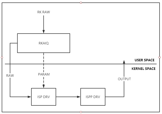
Block diagram of offline frame processing
4.3 Description of the feature
Support RK-RAW file input. With the file input interface, the calling process is blocked until the file processing is complete and the output is successful.
Support RK-RAW buffer input, asynchronous processing mode. Using the buffer input interface, the calling process will not block, and the callback function (if there is a registered callback function) will be called after the buffer processing is completed.
Support RK-RAW buffer input, synchronous processing mode. With the buffer input interface, the calling process will be blocked until the buffer processing is complete and the output is successful.
4.4 RK-RAW format description
See the RK RAW File Format documentation
4.5 Supported RAW formats
Support raw8/raw10/raw12, support BGGR/GBRG/GRBG/RGGB four bayer formats.
4.6 API reference
4.7 Data structures
4.8 Considerations
Using the RK Raw data processing function, when creating an AIQ Context, the parameter sns_ent_name of the rk_aiq_uapi2_sysctl_init interface must be “FakeCamera”.
The processing of raw data relies on IQ XML effect files, and the resolution of the XML file should be generated at the same resolution as the incoming RK Raw frame data. The effect file must be named FakeCamera.xml and placed in the loading path of the XML file.
4.9 Reference example
For more information about how to use the offline frame processing API, see rkisp_demo, and the path is YOUR_SDK_DIR/external/camera_engine_rkaiq/rkisp_demo.
5. Camera group
5.1 Overview
For example, in application scenarios such as surround view, multiple cameras need to be grouped together for unified management, and parameters such as exposure need to be set in a unified manner. You can create a group to classify multiple cameras into the same group. The Camera Group API is implemented based on the AIQ API of a single camera, unless otherwise specified, the API that applies to a single AIQ also applies to a Camera group, and the internal implementation of AIQ will distribute requests to a Camera group or a single Camera according to the type of Context passed.
5.1.1 rk_aiq_uapi2_camgroup_create
【Description】 When you create a Camera group, you will create a separate AIQ ctx for each Camera, and then hand it over to the Group Ctx to manage
【Grammar】
 rk_aiq_camgroup_ctx_t*
 rk_aiq_uapi2_camgroup_create (rk_aiq_camgroup_instance_cfg_t* cfg);
【Parameter】
| Parameter name | Description | Input/Output |
|---|---|---|
| cfg | Configure parameters | Input |
【Return value】
| Return value | Description |
|---|---|
| rk_aiq_camgroup_ctx_t* | Group runtime |
| NULL | fail |
【Demand】
Header files:rk_aiq_user_api2_camgroup.h
Library files:librkaiq.so
【Note】
Different from rk_aiq_uapi2_sysctl_init, rk_aiq_uapi2_sysctl_init create an AIQ runtime environment with a single camera. Use rk_aiq_uapi2_sysctl_init to create a sensor entity that runs and no longer use rk_aiq_uapi2_camgroup_create to create a group runtime and vice versa.
Since the default IQ scene is normal-day, if you need to use HDR or other modes, you need to use rk_aiq_uapi2_sysctl_preInit_scene to set it in advance.
5.1.2 rk_aiq_uapi2_camgroup_prepare
【Description】 According to the selected pipeline mode, initialization parameters are generated and pipelines are created. The rk_aiq_uapi2_sysctl_prepare corresponding to the AIQ ctx of each Camera will be called.
【Grammar】
 XCamReturn
 rk_aiq_uapi2_camgroup_prepare (rk_aiq_camgroup_ctx_t* camgroup_ctx,
 rk_aiq_working_mode_t mode);
【Parameter】
| Parameter name | Description | Input/Output |
|---|---|---|
| camgroup_ctx | Group runtime | Input |
| mode | Pipeline working mode | Input |
【Return value】
| Return value | Description |
|---|---|
| 0 | succeed |
| Non-0 | See Error Codes |
【Demand】
Header files:rk_aiq_user_api2_camgroup.h Library files:librkaiq.so
5.1.3 rk_aiq_uapi2_camgroup_start
【Description】 Run the Camera group. The rk_aiq_uapi2_sysctl_start corresponding to the AIQ ctx of each Camera will be called.
【Grammar】
 XCamReturn
 rk_aiq_uapi2_camgroup_start (rk_aiq_camgroup_ctx_t* camgroup_ctx);
【Parameter】
| Parameter name | Description | Input/Output |
|---|---|---|
| camgroup_ctx | Group runtime | input |
【Return Value】
| Return Value | Description |
|---|---|
| 0 | succeed |
| Non-0 | Failed, see Error Code |
【Demand】
Header files:rk_aiq_user_api2_camgroup.h Library files:librkaiq.so
5.1.4 rk_aiq_uapi2_camgroup_stop
【Description】 Stop the Camera group. The rk_aiq_uapi2_sysctl_stop corresponding to the AIQ ctx of each Camera will be called.
【Grammar】
 XCamReturn
 rk_aiq_uapi2_camgroup_stop (rk_aiq_camgroup_ctx_t* camgroup_ctx);
【Parameter】
| Parameter name | Description | Input/Output |
|---|---|---|
| camgroup_ctx | Group runtime | input |
【Return Value】
| Return Value | Description |
|---|---|
| 0 | succeed |
| Non-0 | Failed, see Error Code |
【Demand】
Header files:rk_aiq_user_api2_camgroup.h Library files:librkaiq.so
5.1.5 rk_aiq_uapi2_camgroup_destroy
【Description】 Destroy the Camera group. The rk_aiq_uapi2_sysctl_deinit corresponding to the AIQ ctx of each Camera will be called.
【Grammar】
 XCamReturn
 rk_aiq_uapi2_camgroup_destroy (rk_aiq_camgroup_ctx_t* camgroup_ctx);
【Parameter】
| Parameter name | Description | Input/Output |
|---|---|---|
| camgroup_ctx | Group runtime | Input |
【Return Value】
| Return Value | Description |
|---|---|
| 0 | succeed |
| Non-0 | Failed, see Error Code |
【Demand】
Header files:rk_aiq_user_api2_camgroup.h Library files:librkaiq.so
5.1.6 rk_aiq_uapi2_camgroup_getOverlapMap
【Description】 In the surround view scenario, obtain the overlapping area information of each camera from the CameraGroup context.
【Grammar】
 struct RK_PS_SrcOverlapMap*
 rk_aiq_uapi2_camgroup_getOverlapMap (rk_aiq_camgroup_ctx_t* camgroup_ctx);
【Parameter】
| Parameter name | Description | Input/Output |
|---|---|---|
| camgroup_ctx | Group runtime | Input |
【Return Value】
| Return Value | Description |
|---|---|
| struct RK_PS_SrcOverlapMap* | Overlapping region information struct pointers |
| NULL | fail |
【Demand】
Header files:rk_aiq_user_api2_camgroup.h Library files:librkaiq.so
5.1.7 rk_aiq_uapi2_camgroup_getOverlapMap
【Description】 In the surround view scenario, you can obtain the overlapping area information of each camera from the file.
【Grammar】
 XCamReturn
 rk_aiq_uapi2_camgroup_getOverlapMap_from_file (const char* map_file,
                                                             struct
 RK_PS_SrcOverlapMap** overlapMap);
【Parameter】
| Parameter name | Description | Input/Output |
|---|---|---|
| map_file | A file that stores overlapping information | Input |
| overlapMap | Stores the acquired overlapping information | Input,Output |
【Return Value】
| Return Value | Description |
|---|---|
| 0 | succeed |
| Non-0 | Failed, see Error Code |
【Demand】
Header files:rk_aiq_user_api2_camgroup.h Library files:librkaiq.so
5.1.8 rk_aiq_uapi2_camgroup_getAiqCtxBySnsNm
【Description】 Obtain the AIQ context of a single Camera by using the Sensor entity name in the group.
【Grammar】
 rk_aiq_sys_ctx_t*
 rk_aiq_uapi2_camgroup_getAiqCtxBySnsNm (rk_aiq_camgroup_ctx_t* camgroup_ctx,
 const char* sns_entity_name);
【Parameter】
| Parameter name | Description | Input/Output |
|---|---|---|
| camgroup_ctx | Group runtime | Input |
| sns_entity_name | The name of the sensor entity in the group | Input |
【Return Value】
| Return Value | Description |
|---|---|
| rk_aiq_sys_ctx_t* | The obtained AIQ runtime environment |
| NULL | fail |
【Demand】
Header files:rk_aiq_user_api2_camgroup.h Library files:librkaiq.so
5.1.9 rk_aiq_uapi2_camgroup_getCamInfos
【Description】 Obtain information about cameras in the group, such as the name of the sensor entity.
【Grammar】
 XCamReturn
 rk_aiq_uapi2_camgroup_getCamInfos (rk_aiq_camgroup_ctx_t* camgroup_ctx,
                    rk_aiq_camgroup_camInfos_t* camInfos);
【Parameter】
| Parameter name | Description | Input/Output |
|---|---|---|
| camgroup_ctx | Group runtime | Input |
| camInfos | Obtained information about the cameras in the group | Output |
【Return Value】
| Return Value | Description |
|---|---|
| 0 | succeed |
| Non-0 | Failed, see Error Code |
【Demand】
Header files:rk_aiq_user_api2_camgroup.h Library files:librkaiq.so
5.1.10 rk_aiq_uapi2_camgroup_bind
【Description】 Reserved interface, not implemented.
5.1.11 rk_aiq_uapi2_camgroup_unbind
【Description】 Reserved interface, not implemented.
5.2 Data Structure
5.2.1 rk_aiq_camgroup_instance_cfg_t
【Illustrate】 Carmelaghrup configuration parameters
【Definition】
   typedef struct rk_aiq_camgroup_instance_cfg_s {
       const char* sns_ent_nm_array[RK_AIQ_CAM_GROUP_MAX_CAMS];
       int sns_num;
       const char* config_file_dir;
        /* followings are relative path to config_file_dir */
        const char* single_iq_file;
        const char* group_iq_file;
        const char* overlap_map_file;
    } rk_aiq_camgroup_instance_cfg_t;
【Member】
| Member Name | Description |
|---|---|
| sns_ent_nm_array | It needs to be added to the Sensor entity array managed by the group |
| sns_num | The number of sensor entities that need to be added to the group |
| config_file_dir | Specify the IQ file path |
| single_iq_file | Specify the IQ file name, which can be NULL, and NULL is automatically selected by AIQ |
| group_iq_file | The specified IQ configuration file of the Camera group is not currently in use |
| overlap_map_file | Specify the Camera overlap information file, which can be NULL |
5.2.2 rk_aiq_camgroup_camInfos_t
【Illustrate】 Information about each camera in the Camera group
【Definition】
    typedef struct rk_aiq_camgroup_camInfos_s {
        int valid_sns_num;
        const char* sns_ent_nm[RK_AIQ_CAM_GROUP_MAX_CAMS];
        int sns_camPhyId[RK_AIQ_CAM_GROUP_MAX_CAMS];
   } rk_aiq_camgroup_camInfos_t;
【Member】
| Member Name | Description |
|---|---|
| valid_sns_num | The number of Sensor entities contained in the group |
| sns_ent_nm | An array of Sensor entity names contained within the group |
| sns_camPhyId | An array of physical IDs corresponding to the Sensor entities contained in the group |
5.2.3 struct RK_PS_SrcOverlapMap
【Illustrate】 Define the overlapping area of the camera
【Definition】
        struct RK_PS_SrcOverlapMap
      {
            char versionInfo[64];
            RK_PS_SrcOverlapPosition srcOverlapPositon[8];
            unsigned char overlapMap[15 * 15 * 8];
        };
【Member】
| Member Name | Description |
|---|---|
| versionInfo | Version information |
| srcOverlapPositon | The rotation direction of each camera can be 0, 90, 180, and 270 degrees |
| overlapMap | The overlapping information of each statistical block of 8 cameras is as follows: the statistical data of each camera is 15*15 columns, a total of 8 cameras (numbered 0~7), and if there are actually less than 8 cameras, the corresponding position is filled with 0. Save by row, after saving the first row of the 8 cameras, then save the second row. And so on. The value range is 0~255, the value is 0 if it is completely non-overlapping, and the value is 255 if it is completely overlapping, and the partial overlap is interpolated according to the proportion camera0 row0; camera1 row0; camera2 row0; camera3 row0; camera4 row0; camera5 row0; camera6 row0; camera7 row0; camera0 row1; camera1 row1; camera2 row1; camera3 row1; camera4 row1; camera5 row1; camera6 row1; camera7 row1; …… camera0 row14; camera1 row14; camera2 row14; camera3 row14; camera4 row14; camera5 row14; camera6 row14; camera7 row14; |
6. AE
6.1 Overview
The AE module achieves the function of obtaining the exposure of the current image according to the automatic metering system, and then automatically configuring the lens aperture, sensor shutter and gain to obtain the best image quality.
6.2 Important concepts
Exposure time: The time when the sensor accumulates charge is the time between the sensor pixel being exposed and the charge is read.
Exposure gain: The total amplification factor of the output charge of the sensor, generally digital gain and analog gain, analog gain will introduce slightly less noise, so analog gain is generally preferred.
Aperture: Aperture is a mechanism in the lens that can change the size of the clear aperture.
Anti-flicker: The picture flicker caused by the mismatch between the power frequency of the lamp and the frame rate of the sensor is generally achieved by limiting the exposure time and modifying the frame rate of the sensor.
6.3 Description of the feature
The AE module consists of AE statistics and the algorithm of AE control strategy.
6.4 Feature-level API reference
6.4.1 rk_aiq_uapi2_setAeLock
【Description】
Set AE exposure lock function.
【Grammar】
XCamReturn rk_aiq_uapi2_setAeLock(const rk_aiq_sys_ctx_t* ctx, bool on);
【Parameters】
| Parameter Name | Description | Input/Output |
|---|---|---|
| sys_ctx | AIQ context pointer | Input |
| on | Lock Enable | Input |
【Return Value】
| Return value | Description |
|---|---|
| 0 | Success |
| Non-0 |
6.4.2 rk_aiq_uapi2_setExpMode
【Description】 Set exposure mode, support setting auto exposure and manual exposure.
【Grammar】
XCamReturn rk_aiq_uapi2_setExpMode(const rk_aiq_sys_ctx_t* ctx, opMode_t mode);
【Parameters】
| Parameter Name | Description | Input/Output |
|---|---|---|
| sys_ctx | AIQ context pointer | Input |
| mode | Exposure Mode | Input |
【Return Value】
| Return value | Description |
|---|---|
| 0 | Success |
| Non-0 | Failure, see Error Code Table |
【Note】
The gain and exposure time when the exposure mode is cut to manual mode use the initial values defined in the image effect file. If you need to set the exposure value while switching the manual mode, you can use the rk_aiq_uapi2_setManualExp interface.
【Requirements】
Header file: rk_aiq_user_api2_imgproc.h
Library file: librkaiq.so
6.4.3 rk_aiq_uapi2_getExpMode
【Description】 Gets the exposure mode.
【Grammar】
XCamReturn rk_aiq_uapi2_getExpMode(const rk_aiq_sys_ctx_t* ctx, opMode_t *mode);
【Parameters】
| Parameter Name | Description | Input/Output |
|---|---|---|
| sys_ctx | AIQ context pointer | Input |
| mode | Exposure Mode | Output |
【Return Value】
| Return value | Description |
|---|---|
| 0 | Success |
| Non-0 | Failure, see Error Code Table |
【Requirements】
Header file: rk_aiq_user_api2_imgproc.h
Library file: librkaiq.so
6.4.4 rk_aiq_uapi2_setManualExp
【Description】 Use the manual exposure mode and set the gain and exposure time.
【Grammar】
 XCamReturn rk_aiq_uapi2_setManualExp(const rk_aiq_sys_ctx_t* ctx, float gain,
 float time);
【Parameters】
| Parameter Name | Description | Input/Output |
|---|---|---|
| sys_ctx | AIQ context pointer | Input |
| gain | Exposure gain | Input |
| time | Exposure time | Input |
【Return Value】
| Return value | Description |
|---|---|
| 0 | Success |
| Non-0 | Failure, see Error Code Table |
【Requirements】
Header file: rk_aiq_user_api2_imgproc.h
Library file: librkaiq.so
6.4.5 rk_aiq_uapi2_setExpGainRange
【Description】** Set the gain range.
【Grammar】
 XCamReturn rk_aiq_uapi2_setExpGainRange(const rk_aiq_sys_ctx_t* ctx, paRange_t
 *gain);
【Parameters】
| Parameter Name | Description | Input/Output |
|---|---|---|
| sys_ctx | AIQ context pointer | Input |
| gain | Exposure gain range | Input |
【Return Value】
| Return value | Description |
|---|---|
| 0 | Success |
| Non-0 | Failure, see Error Code Table |
【Requirements】
Header file: rk_aiq_user_api2_imgproc.h
Library file: librkaiq.so
6.4.6 rk_aiq_uapi2_getExpGainRange
【Description】 Get the gain range.
【Grammar】
 XCamReturn rk_aiq_uapi2_getExpGainRange(const rk_aiq_sys_ctx_t* ctx, paRange_t
 *gain);
【Parameters】
| Parameter Name | Description | Input/Output |
|---|---|---|
| sys_ctx | AIQ context pointer | Input |
| gain | Exposure gain range | Output |
【Return Value】
| Return value | Description |
|---|---|
| 0 | Success |
| Non-0 | Failure, see Error Code Table |
【Requirements】
Header file: rk_aiq_user_api2_imgproc.h
Library file: librkaiq.so
6.4.7 rk_aiq_uapi2_setExpTimeRange
【Description】 Set the exposure time range.
【Grammar】
 XCamReturn rk_aiq_uapi2_setExpTimeRange(const rk_aiq_sys_ctx_t* ctx, paRange_t
 *time);
【Parameters】
| Parameter Name | Description | Input/Output |
|---|---|---|
| sys_ctx | AIQ context pointer | Input |
| time | Exposure time range | Input |
【Return Value】
| Return value | Description |
|---|---|
| 0 | Success |
| Non-0 | Failure, see Error Code Table |
【Requirements】
Header file: rk_aiq_user_api2_imgproc.h
Library file: librkaiq.so
6.4.8 rk_aiq_uapi2_getExpTimeRange
【Description】 Gets the exposure time range.
【Grammar】
 XCamReturn rk_aiq_uapi2_getExpTimeRange(const rk_aiq_sys_ctx_t* ctx, paRange_t
 *time);
【Parameters】
| Parameter Name | Description | Input/Output |
|---|---|---|
| sys_ctx | AIQ context pointer | Input |
| time | Exposure time range | Output |
【Return Value】
| Return value | Description |
|---|---|
| 0 | Success |
| Non-0 | Failure, see Error Code Table |
【Requirements】
Header file: rk_aiq_user_api2_imgproc.h
Library file: librkaiq.so
6.4.9 rk_aiq_uapi2_setBLCMode
【Description】 Backlight compensation switch, locale.
【Grammar】
 XCamReturn rk_aiq_uapi2_setBLCMode(const rk_aiq_sys_ctx_t* ctx, bool on,
 aeMeasAreaType_t areaType);
【Parameters】
| Parameter Name | Description | Input/Output |
|---|---|---|
| ctx | AIQ context pointer | Input |
| on | Switch | Input |
| areaType | Compensation area selection | Input |
【Return Value】
| Return value | Description |
|---|---|
| 0 | Success |
| Non-0 | Failure, see Error Code Table |
【Note】
The interface is only available in linear mode.
【Requirements】
Header file: rk_aiq_user_api2_imgproc.h
Library file: librkaiq.so
6.4.10 rk_aiq_uapi2_setBLCStrength
【Description】 Set dark areas to boost intensity.
【Grammar】
 XCamReturn rk_aiq_uapi2_setBLCStrength(const rk_aiq_sys_ctx_t* ctx, int
 strength);
【Parameters】
| Parameter Name | Description | Input/Output |
|---|---|---|
| ctx | AIQ context pointer | Input |
| strength | Boost intensity, range [1,100] | Input |
【Return Value】
| Return value | Description |
|---|---|
| 0 | Success |
| Non-0 | Failure, see Error Code Table |
【Note】
The interface is only available in linear mode.
【Requirements】
Header file: rk_aiq_user_api2_imgproc.h
Library file: librkaiq.so
6.4.11 rk_aiq_uapi2_setHLCMode
【Description】 Bright light suppression switch.
【Grammar】
XCamReturn rk_aiq_uapi2_setHLCMode(const rk_aiq_sys_ctx_t* ctx, bool on);
【Parameters】
| Parameter Name | Description | Input/Output |
|---|---|---|
| ctx | AIQ context pointer | Input |
| on | Switch | Input |
【Return Value】
| Return value | Description |
|---|---|
| 0 | Success |
| Non-0 | Failure, see Error Code Table |
【Note】
The interface is only available in linear mode.
【Requirements】
Header file: rk_aiq_user_api2_imgproc.h
Library file: librkaiq.so
6.4.12 rk_aiq_uapi2_setHLCStrength
【Description】 Set the intensity of intense light suppression.
【Grammar】
 XCamReturn rk_aiq_uapi2_setHLCStrength(const rk_aiq_sys_ctx_t* ctx, int
 strength);
【Parameters】
| Parameter Name | Description | Input/Output |
|---|---|---|
| ctx | AIQ context pointer | Input |
| strength | Inhibition intensity, range [1,100] | Input |
【Return Value】
| Return value | Description |
|---|---|
| 0 | Success |
| Non-0 | Failure, see Error Code Table |
【Note】
The interface is only available in linear mode.
【Requirements】
Header file: rk_aiq_user_api2_imgproc.h
Library file: librkaiq.sov
6.4.13 rk_aiq_uapi2_setAntiFlickerEn
【Description】 Set the anti-power frequency flicker switch.
【Grammar】
XCamReturn rk_aiq_uapi2_setAntiFlickerEn(const rk_aiq_sys_ctx_t* ctx, bool on);
【Parameters】
| Parameter Name | Description | Input/Output |
|---|---|---|
| sys_ctx | AIQ context pointer | Input |
| on | Function switch parameters | Input |
【Return Value】
| Return value | Description |
|---|---|
| 0 | Success |
| Non-0 | Failure, see Error Code Table |
【Requirements】
Header file: rk_aiq_user_api2_imgproc.h
Library file: librkaiq.so
6.4.14 rk_aiq_uapi2_getAntiFlickerEn
【Description】 Set the anti-power frequency flicker switch.
【Grammar】
XCamReturn rk_aiq_uapi2_getAntiFlickerEn(const rk_aiq_sys_ctx_t* ctx, bool* on);
【Parameters】
| Parameter Name | Description | Input/Output |
|---|---|---|
| sys_ctx | AIQ context pointer | Input |
| on | Function switch parameters | Input |
【Return Value】
| Return value | Description |
|---|---|
| 0 | Success |
| Non-0 | Failure, see Error Code Table |
【Requirements】
Header file: rk_aiq_user_api2_imgproc.h
Library file: librkaiq.so
6.4.15 rk_aiq_uapi2_setAntiFlickerMode
【Description】 Set the anti-flash mode.
【Grammar】
 XCamReturn rk_aiq_uapi2_setAntiFlickerMode(const rk_aiq_sys_ctx_t* ctx,
 antiFlickerMode_t mode);
【Parameters】
| Parameter Name | Description | Input/Output |
|---|---|---|
| sys_ctx | AIQ context pointer | Input |
| mode | Anti-flash mode | Input |
【Return Value】
| Return value | Description |
|---|---|
| 0 | Success |
| Non-0 | Failure, see Error Code Table |
【Requirements】
Header file: rk_aiq_user_api2_imgproc.h
Library file: librkaiq.so
6.4.16 rk_aiq_uapi2_getAntiFlickerMode
【Description】 Get the anti-flash mode.
【Grammar】
 XCamReturn rk_aiq_uapi2_getAntiFlickerMode(const rk_aiq_sys_ctx_t* ctx,
 antiFlickerMode_t *mode);
【Parameters】
| Parameter Name | Description | Input/Output |
|---|---|---|
| sys_ctx | AIQ context pointer | Input |
| mode | Anti-flash mode | Output |
【Return Value】
| Return value | Description |
|---|---|
| 0 | Success |
| Non-0 | Failure, see Error Code Table |
【Requirements】
Header file: rk_aiq_user_api2_imgproc.h
Library file: librkaiq.so
6.4.17 rk_aiq_uapi2_setExpPwrLineFreqMode
【Description】 Set the anti-flash frequency.
【Grammar】
 XCamReturn rk_aiq_uapi2_setExpPwrLineFreqMode(const rk_aiq_sys_ctx_t* ctx,
 expPwrLineFreq_t freq);
【Parameters】
| Parameter Name | Description | Input/Output |
|---|---|---|
| sys_ctx | AIQ context pointer | Input |
| freq | Anti-flash frequency | Input |
【Return Value】
| Return value | Description |
|---|---|
| 0 | Success |
| Non-0 | Failure, see Error Code Table |
【Requirements】
Header file: rk_aiq_user_api2_imgproc.h
Library file: librkaiq.so
6.4.18 rk_aiq_uapi2_getExpPwrLineFreqMode
【Description】** Get the anti-flash frequency.
【Grammar】
 XCamReturn rk_aiq_uapi2_getExpPwrLineFreqMode(const rk_aiq_sys_ctx_t* ctx,
 expPwrLineFreq_t *freq);
【Parameters】
| Parameter Name | Description | Input/Output |
|---|---|---|
| sys_ctx | AIQ context pointer | Input |
| freq | Anti-flash frequency | Output |
【Return Value】
| Return value | Description |
|---|---|
| 0 | Success |
| Non-0 | Failure, see Error Code Table |
【Requirements】
Header file: rk_aiq_user_api2_imgproc.h
Library file: librkaiq.so
6.5 Functional-level API data types
6.5.1 opMode_t
【Description】 Define automatic manual mode.
【Definition】
 typedef enum opMode_e {
     OP_AUTO = 0,
     OP_MANUALl = 1,
     OP_INVAL
 } opMode_t;
【Member】
| Member Name | Description |
|---|---|
| OP_AUTO | Automatic mode |
| OP_MANUALl | Manual mode |
| OP_INVAL | Invalid value |
6.5.2 paRange_t
【Description】 Define parameter ranges.
【Definition】
 typedef struct paRange_s {
     float max;
     float min;
 } paRange_t;
【Member】
| Member Name | Description |
|---|---|
| max | Upper limit value |
| min | Lower limit |
6.5.3 aeMeasAreaType_t
【Description】 Define the AE measurement area type.
【Definition】
 typedef enum aeMeasAreaType_e {
     AE_MEAS_AREA_AUTO = 0,
     AE_MEAS_AREA_UP,
     AE_MEAS_AREA_BOTTOM,
     AE_MEAS_AREA_LEFT,
     AE_MEAS_AREA_RIGHT,
     AE_MEAS_AREA_CENTER,
 } aeMeasAreaType_t;
【Member】
| Member Name | Description |
|---|---|
| AE_MEAS_AREA_AUTO | Automatic |
| AE_MEAS_AREA_UP | Upper area |
| AE_MEAS_AREA_BOTTOM | Lower area |
| AE_MEAS_AREA_LEFT | Left area |
| AE_MEAS_AREA_RIGHT | Right area |
| AE_MEAS_AREA_CENTER | Central Area |
6.5.4 expPwrLineFreq_t
【Description】 Define the anti-flash frequency.
【Definition】
 typedef enum expPwrLineFreq_e {
        EXP_PWR_LINE_FREQ_DIS   = 0,
        EXP_PWR_LINE_FREQ_50HZ  = 1,
        EXP_PWR_LINE_FREQ_60HZ  = 2,
 } expPwrLineFreq_t;
【Member】
| Member Name | Description |
|---|---|
| EXP_PWR_LINE_FREQ_DIS | |
| EXP_PWR_LINE_FREQ_50HZ | 50 Hz |
| EXP_PWR_LINE_FREQ_60HZ | 60 Hz |
6.5.5 antiFlickerMode_t
【Description】 Define the anti-flash mode.
【Definition】
 typedef enum antiFlickerMode_e {
     ANTIFLICKER_NORMAL_MODE = 0,
     ANTIFLICKER_AUTO_MODE = 1,
 } antiFlickerMode_t;
【Member】
| Member Name | Description |
|---|---|
| ANTIFLICKER_NORMAL_MODE | Normal mode |
| ANTIFLICKER_AUTO_MODE | Auto Select Mode |
6.6 Module-level API reference
6.6.1 rk_aiq_user_api2_ae_setExpSwAttr
【Description】 Set AE exposure software properties.
【Grammar】
 XCamReturn
 rk_aiq_user_api2_ae_setExpSwAttr(const rk_aiq_sys_ctx_t* ctx,
                                 const Uapi_ExpSwAttrV2_t expSwAttr);
【Parameters】
| Parameter Name | Description | Input/Output |
|---|---|---|
| ctx | AIQ context pointer | Input |
| expSwAttr | AE Common Function Control Parameter Struct | Input |
【Return Value】
| Return value | Description |
|---|---|
| 0 | Success |
| Non-0 | Failure, see Error Code Table |
【Requirements】
Header files: rk_aiq_user_api2_ae.h, rk_aiq_uapi2_ae_int.h
Library file: librkaiq.so
【Example】
Set manual exposure properties
The exposure components include sensor exposure time, sensor exposure gain, and ISP digital gain. After setting the manual exposure mode, you also need to set the manual state (ManualGainEn, ManualTimeEn, ManualIspDgainEn) and its corresponding manual values for each exposure component. In manual exposure mode, all exposure components are required to be manual, and the value of each exposure component set is limited by the sensor and lens. If the set exposure component value exceeds the sensor’s limit, the algorithm will automatically correct it.
 Uapi_ExpSwAttrV2_t expSwAttr;
 ret = rk_aiq_user_api2_ae_getExpSwAttr(ctx, &expSwAttr);
 expSwAttr.AecOpType = RK_AIQ_OP_MODE_MANUAL;
 //LinearAE
 expSwAttr.stManual.LinearAE.ManualGainEn = true;
 expSwAttr.stManual.LinearAE.ManualTimeEn = true;
 expSwAttr.stManual.LinearAE.GainValue = 1.0f; /*gain = 1x*/
 expSwAttr.stManual.LinearAE.TimeValue = 0.02f; /*time = 1/50s*/
 //HdrAE (should set all frames)
 expSwAttr.stManual.HdrAE.ManualGainEn = true;
 expSwAttr.stManual.HdrAE.ManualTimeEn = true;
 expSwAttr.stManual.HdrAE.GainValue[0] = 1.0f; /*sframe gain = 1x*/
 expSwAttr.stManual.HdrAE.TimeValue[0] = 0.002f; /*sframe time = 1/500s*/
 expSwAttr.stManual.HdrAE.GainValue[1] = 2.0f; /*mframe gain = 2x*/
 expSwAttr.stManual.HdrAE.TimeValue[1] = 0.01f; /*mframe time = 1/100s*/
 expSwAttr.stManual.HdrAE.GainValue[2] = 4.0f; /*lframe gain = 4x*/
 expSwAttr.stManual.HdrAE.TimeValue[2] = 0.02f; /*lframe time = 1/50s*/
 ret = rk_aiq_user_api2_ae_setExpSwAttr(ctx, expSwAttr);
Set auto exposure properties
Auto exposure can set the range of the exposure component, and if the set exposure component range exceeds the limit of the sensor, the algorithm will automatically correct it.
【Note】: Setting the parameters of the exposure component range is different from the parameter of obtaining the exposure component range.
 Uapi_ExpSwAttrV2_t expSwAttr;
 ret = rk_aiq_user_api2_ae_getExpSwAttr(ctx, &expSwAttr);
 expSwAttr.AecOpType = RK_AIQ_OP_MODE_AUTO;
 //set time range in struct "stAdvanced"
 expSwAttr.stAdvanced.SetAeRangeEn = true;/*must enable*/
 //LinAE
 expSwAttr.stAdvanced.SetLinAeRange.stExpTimeRange.Max = 0.04f; /*time_max =
 0.04*/
 expSwAttr.stAdvanced.SetLinAeRange.stExpTimeRange.Min = 0.001f; /*time_min =
 0.001*/
 //HdrAE
 expSwAttr.stAdvanced.SetHdrAeRange.stExpTimeRange[0].Max = 0.002f; /*sframe
 time_max = 0.02*/
 expSwAttr.stAdvanced.SetHdrAeRange.stExpTimeRange[0].Min = 0.001f; /*sframe
 time_min = 0.01*/
 expSwAttr.stAdvanced.SetHdrAeRange.stExpTimeRange[1].Max = 0.003f; /*mframe
 time_max = 0.03*/
 expSwAttr.stAdvanced.SetHdrAeRange.stExpTimeRange[1].Min = 0.002f; /*mframe
 time_min = 0.02*/
 expSwAttr.stAdvanced.SetHdrAeRange.stExpTimeRange[2].Max = 0.04f; /*lframe
 time_max = 0.03*/
 expSwAttr.stAdvanced.SetHdrAeRange.stExpTimeRange[2].Min = 0.03f; /*lframe
 time_min = 0.02*/
 //get time range in struct "stAuto"
 printf("linear time range=[%f,%f]\n",
     expSwAttr.stAuto.LinAeRange.stExpTimeRange.Min,
 expSwAttr.stAuto.LinAeRange.stExpTimeRange.Max);
 printf("hdr stime range=[%f,%f], mtime range=[%f,%f], ltime range=[%f,%f]\n",
     expSwAttr.stAuto.HdrAeRange.stExpTimeRange[0].Min,
 expSwAttr.stAuto.HdrAeRange.stExpTimeRange[0].Max,
     expSwAttr.stAuto.HdrAeRange.stExpTimeRange[1].Min,
 expSwAttr.stAuto.HdrAeRange.stExpTimeRange[1].Max,
     expSwAttr.stAuto.HdrAeRange.stExpTimeRange[2].Min,
 expSwAttr.stAuto.HdrAeRange.stExpTimeRange[2].Max);
 //set gain range in struct "stAdvanced"
 expSwAttr.stAdvanced.SetAeRangeEn = true;/*must enable*/
 //LinAE
 expSwAttr.stAdvanced.SetLinAeRange.stGainRange.Max = 32.0f; /*gain_max = 32x*/
 expSwAttr.stAdvanced.SetLinAeRange.stGainRange.Min = 1.0f; /*gain_min = 1x*/
 //HdrAE
 expSwAttr.stAdvanced.SetHdrAeRange.stGainRange[0].Max = 32.0f; /*sframe gain_max
 = 2x*/
 expSwAttr.stAdvanced.SetHdrAeRange.stGainRange[0].Min = 1.0f; /*sframe gain_min =
 1x*/
 expSwAttr.stAdvanced.SetHdrAeRange.stGainRange[1].Max = 64.0f; /*mframe gain_max
 = 64x*/
 expSwAttr.stAdvanced.SetHdrAeRange.stGainRange[1].Min = 1.0f; /*mframe gian_min =
 1x*/
 expSwAttr.stAdvanced.SetHdrAeRange.stGainRange[2].Max = 64.0f; /*lframe gain_max
 = 64x*/
 expSwAttr.stAdvanced.SetHdrAeRange.stGainRange[2].Min = 1.0f; /*lframe gain_min =
 1x*/
 //get gain range in struct "stAuto"
 printf("linear gain range=[%f,%f]\n",
     expSwAttr.stAuto.LinAeRange.stGainRange.Min,
 expSwAttr.stAuto.LinAeRange.stGainRange.Max);
 printf("hdr sgain range=[%f,%f], mgain range=[%f,%f], lgain range=[%f,%f]\n",
     expSwAttr.stAuto.HdrAeRange.stGainRange[0].Min,
 expSwAttr.stAuto.HdrAeRange.stGainRange[0].Max,
     expSwAttr.stAuto.HdrAeRange.stGainRange[1].Min,
 expSwAttr.stAuto.HdrAeRange.stGainRange[1].Max,
     expSwAttr.stAuto.HdrAeRange.stGainRange[2].Min,
 expSwAttr.stAuto.HdrAeRange.stGainRange[2].Max);
 ret = rk_aiq_user_api2_ae_setExpSwAttr(ctx, expSwAttr);
Set semi-manual exposure properties
Semi-manual exposure is that at least one of the exposure components (sensor exposure time, sensor exposure gain, ISP digital gain) is manual, and the other exposure components are automatic, otherwise it will exit with an error. For example, in order to realize the semi-automatic exposure function of exposure gain manual, exposure time and ISP digital gain automatic, there are the following two ways to implement it: in the manual exposure mode, set the manual enable of exposure time and ISP digital gain to false, set the manual enable of exposure gain to true, and set the corresponding manual value; Method 2: In the auto exposure mode, the maximum and minimum values of the exposure gain are set to the value that needs to be fixed.
【Note】Method 1: In HDR exposure mode, the manual behavior of all frames is synchronous (that is, the corresponding exposure components of each frame are manually consistent), and at the same time, it is necessary to ensure that the maximum exposure of long frames is greater than the maximum exposure of short frames, and the minimum exposure of long frames is greater than the minimum exposure of short frames; Method 2: In HDR exposure mode, the manual behavior of each frame is allowed to be inconsistent (such as short frame gain manual, long frame gain can be automatic), and at the same time, you need to ensure that the maximum exposure of long frames is greater than the maximum exposure of short frames, and the minimum exposure of long frames is greater than the minimum exposure of short frames.
 //Method One
 Uapi_ExpSwAttrV2_t expSwAttr;
 ret = rk_aiq_user_api2_ae_getExpSwAttr(ctx, &expSwAttr);
 expSwAttr.AecOpType = RK_AIQ_OP_MODE_MANUAL;
 //LinearAE
 expSwAttr.stManual.LinearAE.ManualGainEn = true;
 expSwAttr.stManual.LinearAE.ManualTimeEn = false;
 expSwAttr.stManual.LinearAE.ManualIspDgainEn = false;
 expSwAttr.stManual.LinearAE.GainValue = 2.0f; /*gain = 2x*/
 //HdrAE (need to set all frames)
 expSwAttr.stManual.HdrAE.ManualGainEn = true;
 expSwAttr.stManual.HdrAE.ManualTimeEn = false;
 expSwAttr.stManual.HdrAE.ManualIspDgainEn = false;
 expSwAttr.stManual.HdrAE.GainValue[0] = 1.0f; /*sframe gain = 1x*/
 expSwAttr.stManual.HdrAE.GainValue[1] = 2.0f; /*mframe gain = 2x*/
 expSwAttr.stManual.HdrAE.GainValue[2] = 4.0f; /*lframe gain = 4x*/
 ret = rk_aiq_user_api2_ae_setExpSwAttr(ctx, expSwAttr);
 //Method Two
 Uapi_ExpSwAttrV2_t expSwAttr;
 ret = rk_aiq_user_api2_ae_getExpSwAttr(ctx, &expSwAttr);
 expSwAttr.AecOpType = RK_AIQ_OP_MODE_AUTO;
 //set gain range
 expSwAttr.stAdvanced.SetAeRangeEn = true;/*Must be enabled*/
 //LinAE
 expSwAttr.stAdvanced.SetLinAeRange.stGainRange.Max = 2.0f; /*gain_max = 2x*/
 expSwAttr.stAdvanced.SetLinAeRange.stGainRange.Min = 2.0f;  /*gain_min = 2x*/
 //HdrAE (allow to set only one frame)
 expSwAttr.stAdvanced.SetHdrAeRange.stGainRange[0].Max = 2.0f; /*sframe gain_max =
 2x*/
 expSwAttr.stAdvanced.SetHdrAeRange.stGainRange[0].Min = 2.0f;  /*sframe gain_min
 = 2x*/
 ret = rk_aiq_user_api2_ae_setExpSwAttr(ctx, expSwAttr);
Set a fixed frame rate or automatic frame reduction
In fixed frame rate mode, the allowed frame rate must not exceed the maximum frame rate defined by the driver, if it exceeds it, there will be a log reminder and the frame rate setting will be disabled.
 //set fixed framemode
 Uapi_ExpSwAttrV2_t expSwAttr;
 ret = rk_aiq_user_api2_ae_getExpSwAttr(ctx, &expSwAttr);
 expSwAttr.stAuto.stFrmRate.isFpsFix = true;
 expSwAttr.stAuto.stFrmRate.FpsValue = 25; /*fps = 25*/
 ret = rk_aiq_user_api2_ae_setExpSwAttr(ctx, expSwAttr);
 //set auto framemode
 Uapi_ExpSwAttrV2_t expSwAttr;
 ret = rk_aiq_user_api2_ae_getExpSwAttr(ctx, &expSwAttr);
 expSwAttr.stAuto.stFrmRate.isFpsFix = false;
 /*Generally, the automatic frame reduction mode is configured by tuning personnel
 in advance with the minimum frame rate and the gain value corresponding to the
 switching frame rate*/
 ret = rk_aiq_user_api2_ae_setExpSwAttr(ctx, expSwAttr);
Set the exposure adjustment speed and delay frame rate
 Uapi_ExpSwAttrV2_t expSwAttr;
 ret = rk_aiq_user_api2_ae_getExpSwAttr(ctx, &expSwAttr);
 //set ae speed
 expSwAttr.stAuto.stAeSpeed.DampOver = 0.8f;
 expSwAttr.stAuto.stAeSpeed.DampDark2Bright = 0.8f;
 expSwAttr.stAuto.stAeSpeed.DampUnder = 0.8f;
 expSwAttr.stAuto.stAeSpeed.DampBright2Dark = 0.8f;
 //set ae delay
 expSwAttr.stAuto.BlackDelayFrame = 2;
 expSwAttr.stAuto.WhiteDelayFrame = 4;
 ret = rk_aiq_user_api2_ae_setExpSwAttr(ctx, expSwAttr);
Set up anti-flash
 Uapi_ExpSwAttr_t expSwAttr;
 ret = rk_aiq_user_api2_ae_getExpSwAttr(ctx, &expSwAttr);
 //set antifilicker mode
 expSwAttr.stAuto.stAntiFlicker.enable = true;
 expSwAttr.stAuto.stAntiFlicker.Frequency = AECV2_FLICKER_FREQUENCY_50HZ;
 expSwAttr.stAuto.stAntiFlicker.Mode = AECV2_ANTIFLICKER_AUTO_MODE;
 ret = rk_aiq_user_api2_ae_setExpSwAttr(ctx, expSwAttr);
Set the AE weight
Set the 15X15 weight, and the algorithm compresses the weight according to the actual block specifications of the hardware. At present, there are two ways to set the weight: way 1: directly modify the weight in JSON; Method 2: Modify the weight by stadvanced, and if you eliminate the enablement, you can restore the weight back to the JSON (this method is recommended).
For face applications, the recommended use of expSwAttr.stAdvanced.enable = true, use the weight in the expSwAttr.stAdvanced structure when the face appears, and expSwAttr.stAdvanced.enable = false when the face disappears, use the original weight.
 Uapi_ExpSwAttr_t expSwAttr;
 ret = rk_aiq_user_api2_ae_getExpSwAttr(ctx, &expSwAttr);
 uint8_t GridWeights[225]={
 0,  0, 1,  2,  2,  3,  4,  5,  4, 3,  2,  2,  1,  0,  0,
 0,  1, 2,  3,  3,  4,  5,  6,  5, 4,  3,  3,  2,  1,  0,
 1,  2, 3,  5,  5,  6,  7,  8,  7, 6,  5,  5,  3,  2,  1,
 2,  3, 5,  7,  7,  8,  9, 10,  9, 8,  7,  7,  5,  3,  2,
 2,  3, 5,  7,  8,  9, 10, 11, 10, 9,  8,  7,  5,  3,  2,
 2,  4, 6,  8,  9, 10, 11, 12, 11,10,  9,  8,  6,  4,  2,
 2,  4, 6,  9, 10, 11, 12, 13, 12,11, 10,  9,  6,  4,  2,
 3,  5 ,7, 10, 11, 12, 13, 14, 13,12, 11, 10,  7,  5,  3,
 2,  4, 6,  9, 10, 11, 12, 13, 12,11, 10,  9,  6,  4,  2,
 2,  4, 6,  8,  9, 10, 11, 12, 11,10,  9,  8,  6,  4,  2,
 2,  3, 5,  7,  8,  9, 10, 11, 10, 9,  8,  7,  5,  3,  2,
 2,  3, 5,  7,  7,  8,  9, 10,  9, 8,  7,  7,  5,  3,  2,
 1,  2, 4,  6,  6,  7,  8,  9,  8, 7,  6,  6,  4,  2,  1,
 0,  1, 3,  5,  5,  6,  7,  8,  7, 6,  5,  5,  3,  1,  0,
 0,  1, 3,  5,  5,  6,  7,  8,  7, 6,  5,  5,  3,  1,  0
 };
 //method one:
 memcpy(expSwAttr.GridWeights.uCoeff, GridWeights,
 sizeof(expSwAttr.GridWeights.uCoeff));
 //method two:
 expSwAttr.stAdvanced.enable = true; //important! true means preferring to use these parameters
 memcpy(expSwAttr.stAdvanced.GridWeights, GridWeights,
 sizeof(expSwAttr.stAdvanced.GridWeights));
 ret = rk_aiq_user_api2_ae_setExpSwAttr(ctx, expSwAttr);
6.6.2 rk_aiq_user_api2_ae_getExpSwAttr
【Description】 Gets the AE exposure software properties.
【Grammar】
 XCamReturn
 rk_aiq_user_api2_ae_getExpSwAttr(const rk_aiq_sys_ctx_t* ctx,
                         Uapi_ExpSwAttrV2_t* pExpSwAttr);
【Parameters】
| Parameter Name | Description | Input/Output |
|---|---|---|
| ctx | AIQ context pointer | Input |
| pExpSwAttr | AE Exposure Software Properties Structure Pointer | Output |
【Return Value】
| Return value | Description |
|---|---|
| 0 | Success |
| Non-0 | Failure, see Error Code Table |
【Requirements】
Header files: rk_aiq_user_api2_ae.h, rk_aiq_uapi2_ae_int.h
Library file: librkaiq.so
6.6.3 rk_aiq_user_api2_ae_setLinAeRouteAttr
【Description】 Set the scene exposure allocation strategy for AE in linear mode.
【Grammar】
 XCamReturn
 rk_aiq_user_api2_ae_setLinAeRouteAttr(const rk_aiq_sys_ctx_t* ctx, const
 Uapi_LinAeRouteAttr_t linAeRouteAttr);
【Parameters】
| Parameter Name | Description | Input/Output |
|---|---|---|
| ctx | AIQ context pointer | Input |
| linAeRouteAttr | AE Exposure Allocation Strategy Structure | Input |
【Return Value】
| Return value | Description |
|---|---|
| 0 | Success |
| Non-0 | Failure, see Error Code Table |
【Requirements】
Header files: rk_aiq_user_api2_ae.h, rk_aiq_uapi2_ae_int.h
Library file: librkaiq.so
【Example】
 Uapi_LinAeRouteAttr_t LinAeRouteAttr;
 memset(&LinAeRouteAttr,0x00,sizeof(Uapi_LinAeRouteAttr_t));
 rk_aiq_user_api2_ae_getLinAeRouteAttr(sys_ctx,&LinAeRouteAttr);
 int len = 8;
 float TimeDot[8]={0,0.01,0.01,0.02,0.02,0.03,0.03,0.04};
 float GainDot[8]={1,1,4,4,8,8,16,32};
 float IspGainDot[8]={1,1,1,1,1,1,1,1};
 int PirisDot[8]={512,512,512,512,512,512,512,512};
 LinAeRouteAttr.TimeDot_len = len;
 LinAeRouteAttr.GainDot_len = len;
 LinAeRouteAttr.IspDGainDot_len = len;
 LinAeRouteAttr.PIrisDot_len = len;
 LinAeRouteAttr.GainDot = GainDot;
 LinAeRouteAttr.IspDGainDot = IspGainDot;
 LinAeRouteAttr.TimeDot = TimeDot;
 LinAeRouteAttr.PIrisDot = PirisDot;
 rk_aiq_user_api2_ae_setLinAeRouteAttr(sys_ctx,LinAeRouteAttr);
6.6.4 rk_aiq_user_api2_ae_getLinAeRouteAttr
【Description】 Gets the scene exposure allocation strategy for AE in linear mode.
【Grammar】
 XCamReturn
 rk_aiq_user_api2_ae_getLinAeRouteAttr(const rk_aiq_sys_ctx_t* ctx,
 Uapi_LinAeRouteAttr_t* pLinAeRouteAttr);
【Parameters】
| Parameter Name | Description | Input/Output |
|---|---|---|
| ctx | AIQ context pointer | Input |
| pLinAeRouteAttr | AE Exposure Allocation Strategy Structure Pointer | Output |
【Return Value】
| Return value | Description |
|---|---|
| 0 | Success |
| Non-0 | Failure, see Error Code Table |
【Requirements】
Header files: rk_aiq_user_api2_ae.h, rk_aiq_uapi2_ae_int.h
Library file: librkaiq.so
6.6.5 rk_aiq_user_api2_ae_setHdrAeRouteAttr
【Description】 Set the scene exposure allocation strategy for AE in HDR mode.
【Grammar】
 XCamReturn
 rk_aiq_user_api2_ae_setHdrAeRouteAttr(const rk_aiq_sys_ctx_t* ctx, const
 Uapi_HdrAeRouteAttr_t hdrAeRouteAttr);
【Parameters】
| Parameter Name | Description | Input/Output |
|---|---|---|
| ctx | AIQ context pointer | Input |
| hdrAeRouteAttr | AE Exposure Allocation Strategy Structure | Input |
【Return Value】
| Return value | Description |
|---|---|
| 0 | Success |
| Non-0 | Failure, see Error Code Table |
【Requirements】
Header files: rk_aiq_user_api2_ae.h, rk_aiq_uapi2_ae_int.h
Library file: librkaiq.so
【Example】
 Uapi_HdrAeRouteAttr_t stHdrRoute;
 memset(&stHdrRoute,0x00,sizeof(Uapi_HdrAeRouteAttr_t));
 ret = rk_aiq_user_api2_ae_getHdrAeRouteAttr(ctx,&stHdrRoute);
 int len = 6;
 float HdrTimeDot[3][6] = {0.0, 0.01, 0.01, 0.01, 0.01, 0.01,
                           0.0, 0.02, 0.02, 0.02, 0.02, 0.02,
                           0.0, 0.03, 0.03, 0.03, 0.03, 0.03};
 float HdrGainDot[3][6] = {1, 1, 4, 6, 8, 12,
                           1, 1, 4, 6, 8, 12,
                           1, 1, 4, 6, 8, 12};
 float HdrIspDGainDot[3][6] = {1, 1, 1, 1, 1, 1,
                               1, 1, 1, 1, 1, 1,
                               1, 1, 1, 1, 1, 1};
 int   HdrPIrisGainDot[6] = {1, 1, 1, 1, 1, 1};
 stHdrRoute.Frm0TimeDot_len = len;
 stHdrRoute.Frm0GainDot_len = len;
 stHdrRoute.Frm0IspDGainDot_len = len;
 stHdrRoute.Frm1TimeDot_len = len;
 stHdrRoute.Frm1GainDot_len = len;
 stHdrRoute.Frm1IspDGainDot_len = len;
 stHdrRoute.Frm2TimeDot_len = len;
 stHdrRoute.Frm2GainDot_len = len;
 stHdrRoute.Frm2IspDGainDot_len = len;
 stHdrRoute.PIrisDot_len = len;
 stHdrRoute.Frm0TimeDot = HdrTimeDot[0];
 stHdrRoute.Frm0GainDot = HdrGainDot[0];
 stHdrRoute.Frm0IspDGainDot = HdrIspDGainDot[0];
 stHdrRoute.Frm1TimeDot = HdrTimeDot[1];
 stHdrRoute.Frm1GainDot = HdrGainDot[1];
 stHdrRoute.Frm1IspDGainDot = HdrIspDGainDot[1];
 stHdrRoute.Frm2TimeDot = HdrTimeDot[2];
 stHdrRoute.Frm2GainDot = HdrGainDot[2];
 stHdrRoute.Frm2IspDGainDot = HdrIspDGainDot[2];
 stHdrRoute.PIrisDot = HdrPIrisGainDot;
 ret = rk_aiq_user_api2_ae_setHdrAeRouteAttr(ctx,stHdrRoute);
6.6.6 rk_aiq_user_api2_ae_getHdrAeRouteAttr
【Description】 Gets the scene exposure distribution strategy for AE in HDR mode.
【Grammar】
 XCamReturn
 rk_aiq_user_api2_ae_getHdrAeRouteAttr(const rk_aiq_sys_ctx_t* ctx,
 Uapi_HdrAeRouteAttr_t* pHdrAeRouteAttr);
【Parameters】
| Parameter Name | Description | Input/Output |
|---|---|---|
| ctx | AIQ context pointer | Input |
| pHdrAeRouteAttr | AE Exposure Allocation Strategy Structure Pointer | Output |
【Return Value】
| Return value | Description |
|---|---|
| 0 | Success |
| Non-0 | Failure, see Error Code Table |
【Requirements】
Header files: rk_aiq_user_api2_ae.h, rk_aiq_uapi2_ae_int.h
Library file: librkaiq.so
6.6.7 rk_aiq_user_api2_ae_setLinExpAttr
【Description】 Set the AE linear mode exposure parameters.
【Grammar】
 XCamReturn
 rk_aiq_user_api2_ae_setLinExpAttr(const rk_aiq_sys_ctx_t* ctx, const
 Uapi_LinExpAttrV2_t linExpAttr);
【Parameters】
| Parameter Name | Description | Input/Output |
|---|---|---|
| ctx | AIQ context pointer | Input |
| linExpAttr | AE exposure parameter structure | Input |
【Return Value】
| Return value | Description |
|---|---|
| 0 | Success |
| Non-0 | Failure, see Error Code Table |
【Requirements】
Header files: rk_aiq_user_api2_ae.h, rk_aiq_uapi2_ae_int.h
Library file: librkaiq.so
【Example】
Set AE linear mode exposure parameters, including but not limited to: setting to adjust brightness intensity Evbias, setting backlight compensation function BackLightCtrl, setting strong light suppression function OverExpCtrl, etc. It is important to note that backlight compensation and strong light suppression cannot be enabled at the same time.
 Uapi_LinExpAttrV2_t linExpAttr;
 memset(&linExpAttr,0,sizeof(Uapi_LinExpAttrV2_t));
 ret = rk_aiq_user_api2_ae_getLinExpAttr(ctx, &linExpAttr);
 //set Evbias
 printf("Evbias=%f\n", linExpAttr.Evbias);
 linExpAttr.Evbias = 100.0f;
 //set BackLightCtrl
 linExpAttr.BackLightCtrl.Enable = true;
 linExpAttr.BackLightCtrl.StrBias = 200.0f;
 //set OverExpCtrl
 linExpAttr.OverExpCtrl.Enable = true;
 linExpAttr.OverExpCtrl.StrBias = 100.0f;
 ret = rk_aiq_user_api2_ae_setLinExpAttr(ctx, linExpAttr);
6.6.8 rk_aiq_user_api2_ae_getLinExpAttr
【Description】 Get the AE linear mode exposure parameters.
【Grammar】
 XCamReturn
 rk_aiq_user_api2_ae_getLinExpAttr(const rk_aiq_sys_ctx_t* ctx,
 Uapi_LinExpAttrV2_t* pLinExpAttr);
【Parameters】
| Parameter Name | Description | Input/Output |
|---|---|---|
| ctx | AIQ context pointer | Input |
| pLinExpAttr | AE exposure parameter structure pointer | Output |
【Return Value】
| Return value | Description |
|---|---|
| 0 | Success |
| Non-0 | Failure, see Error Code Table |
【Requirements】
Header files: rk_aiq_user_api2_ae.h, rk_aiq_uapi2_ae_int.h
Library file: librkaiq.so
6.6.9 rk_aiq_user_api2_ae_setHdrExpAttr
【Description】 Set AE HDR mode exposure parameters.
【Grammar】
 XCamReturn
 rk_aiq_user_api2_ae_setHdrExpAttr(const rk_aiq_sys_ctx_t* ctx, const
 Uapi_HdrExpAttrV2_t hdrExpAttr);
【Parameters】
| Parameter Name | Description | Input/Output |
|---|---|---|
| ctx | AIQ context pointer | Input |
| hdrExpAttr | AE exposure parameter structure | Input |
【Return Value】
| Return value | Description |
|---|---|
| 0 | Success |
| Non-0 | Failure, see Error Code Table |
【Requirements】
Header files: rk_aiq_user_api2_ae.h, rk_aiq_uapi2_ae_int.h
Library file: librkaiq.so
【Example】
Set AE HDR mode exposure parameters, including but not limited to: setting the exposure ratio to manual or automatic, adjusting the brightness intensity Evbias.
 Uapi_HdrExpAttrV2_t HdrExpAttr;
 memset(&HdrExpAttr,0,sizeof(Uapi_HdrExpAttrV2_t));
 ret = rk_aiq_user_api2_ae_getHdrExpAttr(ctx, &HdrExpAttr);
 //set hdr mframe params
 int len = 8;
 float explevel[8] = {0, 0.096, 0.192, 0.384, 0.96, 1.344, 1.92, 3};
 float setpoint[8] = {50, 45, 40, 35, 30, 25, 20, 15};
 HdrExpAttr.HdrAEAttr.MframeCtrl.MExpLevel_len = len;
 HdrExpAttr.HdrAEAttr.MframeCtrl.MSetPoint_len = len;
 HdrExpAttr.HdrAEAttr.MframeCtrl.MExpLevel = explevel;
 HdrExpAttr.HdrAEAttr.MframeCtrl.MSetPoint = setpoint;
 //set ExpRatioType (AUTO/FIX)
 HdrExpAttr.ExpRatioCtrl.ExpRatioType = AECV2_HDR_RATIOTYPE_MODE_AUTO;
 //set Evbias
 HdrExpAttr.Evbias = -100.0f;
 ret = rk_aiq_user_api2_ae_setHdrExpAttr(ctx, HdrExpAttr);
6.6.10 rk_aiq_user_api2_ae_getHdrExpAttr
【Description】 Get the AE HDR mode exposure parameters.
【Grammar】
 XCamReturn
 rk_aiq_user_api2_ae_getHdrExpAttr(const rk_aiq_sys_ctx_t* ctx,
 Uapi_HdrExpAttrV2_t* pHdrExpAttr);
【Parameters】
| Parameter Name | Description | Input/Output |
|---|---|---|
| ctx | AIQ context pointer | Input |
| pHdrExpAttr | AE exposure parameter structure pointer | Output |
【Return Value】
| Return value | Description |
|---|---|
| 0 | Success |
| Non-0 | Failure, see Error Code Table |
【Requirements】
Header files: rk_aiq_user_api2_ae.h, rk_aiq_uapi2_ae_int.h
Library file: librkaiq.so
6.6.11 rk_aiq_user_api2_ae_setIrisAttr
【Description】 Set AE aperture control parameters.
【Grammar】
 XCamReturn
 rk_aiq_user_api2_ae_setIrisAttr(const rk_aiq_sys_ctx_t * sys_ctx, const
 Uapi_IrisAttrV2_t irisAttr);
【Parameters】
| Parameter Name | Description | Input/Output |
|---|---|---|
| ctx | AIQ context pointer | Input |
| irisAttr | Aperture control parameter structure | Input |
【Return Value】
| Return value | Description |
|---|---|
| 0 | Success |
| Non-0 | Failure, see Error Code Table |
【Requirements】
Header files: rk_aiq_user_api2_ae.h, rk_aiq_uapi2_ae_int.h
Library file: librkaiq.so
【Example】
 Uapi_IrisAttrV2_t irisAttr;
 ret = rk_aiq_user_api2_ae_getIrisAttr(ctx, &irisAttr);
 irisAttr.enable = true; /*run AIris*/
 //set P-iris attributes
 irisAttr.IrisType = IRIS_P_TYPE;
 irisAttr.PIrisAttr.TotalStep = 81;
 irisAttr.PIrisAttr.EffcStep = 44;
 irisAttr.PIrisAttr.ZeroIsMax = true;
 uint16_t StepTable[1024] = {512, 511, 506, 499, 491, 483, 474, 465, 456,
                             446, 437, 427, 417, 408, 398, 388, 378, 368,
                             359, 349, 339, 329, 319, 309, 300, 290, 280,
                             271, 261, 252, 242, 233, 224, 214, 205, 196,
                             187, 178, 170, 161, 153, 144, 136, 128, 120,
                             112, 105, 98, 90, 83, 77, 70, 64, 58,
                             52, 46, 41, 36, 31, 27, 23, 19, 16,
                             13, 10, 8, 6, 4, 3, 1, 1, 0,
                             0, 0, 0, 0, 0, 0, 0, 0, 0};
 memcpy(irisAttr.PIrisAttr.StepTable,StepTable,sizeof(irisAttr.PIrisAttr.StepTable
 ));
 ret = rk_aiq_user_api2_ae_setIrisAttr(ctx, irisAttr);
 //set DC-iris attributes
 irisAttr.IrisType = IRIS_DC_TYPE;
 irisAttr.DCIrisAttr.Kp= 0.5f;
 irisAttr.DCIrisAttr.Ki= 0.2f;
 irisAttr.DCIrisAttr.Kd = 0.3f;
 irisAttr.DCIrisAttr.OpenPwmDuty = 40;
 irisAttr.DCIrisAttr.ClosePwmDuty = 22;
 irisAttr.DCIrisAttr.MinPwmDuty = 0;
 irisAttr.DCIrisAttr.MaxPwmDuty = 100;
 ret = rk_aiq_user_api2_ae_setIrisAttr(ctx, irisAttr);
 //set manual iris with auto ae
 irisAttr.IrisOpType = RK_AIQ_OP_MODE_MANUAL;
 if(irisAttr.IrisType == IRIS_P_TYPE);
     irisAttr.ManualAttr.PIrisGainValue = 512; /*p-iris F#=1.4*/
 if(irisAttr.IrisType == IRIS_DC_TYPE);
     irisAttr.ManualAttr.DCIrisHoldValue = 20; /*dc-iris PwmDuty=20*/
 ret = rk_aiq_user_api2_ae_setIrisAttr(ctx, irisAttr);
6.6.12 rk_aiq_user_api2_ae_getIrisAttr
【Description】 Gets the AE aperture control parameters.
【Grammar】
 XCamReturn
 rk_aiq_user_api2_ae_getIrisAttr(const rk_aiq_sys_ctx_t * sys_ctx, const
 Uapi_IrisAttrV2_t* irisAttr);
【Parameters】
| Parameter Name | Description | Input/Output |
|---|---|---|
| ctx | AIQ context pointer | Input |
| irisAttr | Aperture control parameter structure | Output |
【Return Value】
| Return value | Description |
|---|---|
| 0 | Success |
| Non-0 | Failure, see Error Code Table |
【Requirements】
Header files: rk_aiq_user_api2_ae.h, rk_aiq_uapi2_ae_int.h
Library file: librkaiq.so
6.6.13 rk_aiq_user_api2_ae_setExpWinAttr
【Description】 Set the AE Statistics window properties.
【Grammar】
 XCamReturn
 rk_aiq_user_api2_ae_setExpWinAttr(const rk_aiq_sys_ctx_t* sys_ctx, const
 Uapi_ExpWin_t ExpWin);
【Parameters】
| Parameter Name | Description | Input/Output |
|---|---|---|
| ctx | AIQ context pointer | Input |
| ExpWin | Window Properties Parameter | Input |
【Return Value】
| Return value | Description |
|---|---|
| 0 | Success |
| Non-0 | Failure, see Error Code Table |
【Requirements】
Header files: rk_aiq_user_api2_ae.h, rk_aiq_uapi2_ae_int.h
Library file: librkaiq.so
【Example】
Modify the AE statistical coordinates according to the face position to realize brightness statistics for the face area.
Note: When setting statistical coordinates, ensure that ExpWin.h_offs+ExpWin.h_size<=pic_width and ExpWin.v_offs+ExpWin.v_size<=pic_height.
 Uapi_ExpWin_t ExpWin;
 //Suppose the sensor resolution is 2688X1520, the lateral offset of the face from the upper left corner of the screen is 100 pixel, the vertical offset is 100 pixel, and the face size is a square with a side length of 100 pixel
 ExpWin.h_offs=100;
 ExpWin.v_offs=100;
 ExpWin.h_size=100;
 ExpWin.v_size=100;
 rk_aiq_user_api2_ae_setExpWinAttr(ctx, ExpWin);
6.6.14 rk_aiq_user_api2_ae_getExpWinAttr
【Description】 Gets the AE Statistics window properties.
【Grammar】
 XCamReturn
 rk_aiq_user_api2_ae_getExpWinAttr(const rk_aiq_sys_ctx_t* sys_ctx,const
 Uapi_ExpWin_t* ExpWin);
【Parameters】
| Parameter Name | Description | Input/Output |
|---|---|---|
| ctx | AIQ context pointer | Input |
| ExpWin | Window Properties Parameter | Output |
【Return Value】
| Return value | Description |
|---|---|
| 0 | Success |
| Non-0 | Failure, see Error Code Table |
【Requirements】
Header files: rk_aiq_user_api2_ae.h, rk_aiq_uapi2_ae_int.h
Library file: librkaiq.so
6.6.15 rk_aiq_user_api2_ae_queryExpResInfo
【Description】 Obtain AE internal state information.
【Grammar】
 XCamReturn
 rk_aiq_user_api2_ae_queryExpResInfo(const rk_aiq_sys_ctx_t* ctx,
 Uapi_ExpQueryInfo_t* pExpResInfo);
【Parameters】
| Parameter Name | Description | Input/Output |
|---|---|---|
| ctx | AIQ context pointer | Input |
| pExpResInfo | AE Internal State Information Structure Pointer | Output |
【Return Value】
| Return value | Description |
|---|---|
| 0 | Success |
| Non-0 | Failure, see Error Code Table |
【Requirements】
Header files: rk_aiq_user_api2_ae.h, rk_aiq_uapi2_ae_int.h
Library file: librkaiq.so
6.7 Module-level API data types
6.7.1 Uapi_ExpSwAttr_t
【Description】
AE common function control parameter structure.
【Definition】
 typedef struct Uapi_ExpSwAttrV2_s {
     rk_aiq_uapi_sync_t                 sync;
     uint8_t                            Enable;
     CalibDb_CamRawStatsModeV2_t        RawStatsMode;
     CalibDb_CamHistStatsModeV2_t       HistStatsMode;
     CalibDb_CamYRangeModeV2_t          YRangeMode;
     uint8_t                            AecRunInterval;
     RKAiqOPMode_t                      AecOpType;
     Cam15x15UCharMatrix_t              GridWeights;
     Uapi_AeAttrV2_t                    stAuto;
     Uapi_MeAttrV2_t                    stManual;
     Uapi_ExpSwAttr_AdvancedV2_t        stAdvanced;
 } Uapi_ExpSwAttrV2_t;
【Member】
| Member Name |
Description |
|---|---|
| sync | For rk_aiq_uapi_sync_t definitions, see Overview/API Description section |
| Enable | AEC enable switch. 1. Turn on the Aec algorithm; 0, turn off the Aec algorithm, and the exposure remains at the value before it turned off |
| RawStatsMode | AEC module luminance statistics mode. There are four modes: CAM_RAWSTATSV2_MODE_Y/R/G/B, and the default is Y mode. |
| HistStatsMode | AEC module histogram statistical mode. There are five modes: CAM_HISTV2_MODE_Y/R/G/B, and the default is Y mode. |
| YRangeMode | Aec module Y-channel Range mode. The two modes are CAM_YRANGEV2_MODE_FULL/LIMITED, and the default is FULL mode. |
| AecRunInterval | The AE algorithm runs at a value range of [0,255], and the default value is 0. If the value is 0, run AE every frame; If the value is 1, run AE every 1 frame; And so on. |
| AecOpType | Exposure modes, divided into auto exposure (RK_AIQ_OP_MODE_AUTO) mode / manual (RK_AIQ_OP_MODE_MANUAL) exposure mode. The default is AUTO mode. Manual exposure mode needs to be used in conjunction with stManual to set the manual exposure value |
| GridWeights | Window (histogram) weight, containing 15*15 array elements, value range [0,32] |
| stAuto | Auto exposure parameter structure |
| stManual | Manual exposure parameter structure |
| stAdvanced | Parameter structs |
Related Data Type
rk_aiq_uapi_sync_t
Uapi_ExpSwAttr_AdvancedV2_t
Uapi_AeAttrV2_t
Uapi_MeAttrV2_t
6.7.1.1 Uapi_ExpSwAttr_AdvancedV2_t
【Description】
Parameter structs are preferred.
【Definition】
 typedef struct Aec_uapi_advanced_attr_s {
     bool                          enable;
     uint8_t                       GridWeights[15 * 15];
     bool                          SetAeRangeEn;
     Aec_LinAeRange_t              SetLinAeRange;
     Aec_HdrAeRange_t              SetHdrAeRange;
 } Aec_uapi_advanced_attr_t;
 typedef Aec_uapi_advanced_attr_t Uapi_ExpSwAttr_AdvancedV2_t;
【Member】
| Member Name | Description |
|---|---|
| enable | set 1 to give preference to the parameters in the struct |
| GridWeights | AE weight, size 15X15. |
| SetAeRangeEn | Set 1 to set the auto exposure component range; Set 0, do not set the auto exposure component range, subject to the debug file |
| SetLinAeRange | The value of the range parameter of the auto exposure component of linear exposure (not the final effective range) |
| SetHdrAeRange | The automatic exposure component of HDR exposure range parameter value (not the final effective range) |
【Precautions】
Uapi_ExpSwAttrV2_t A set of AE weights is defined in the structure, and the number of weights is 15X15. The algorithm expands the weights according to the actual number of weights configured by the hardware. If you need to expose a similar face, you can use a set of AE weights defined in the Uapi_ExpSwAttr_AdvancedV2_t, and the number of weights is 15X15. The algorithm compresses the weights according to the actual number of weights configured by the hardware. If you want to use a set of AE weights defined in the Uapi_ExpSwAttr_Advanced_t, enable must be enabled and set to 1.
When setting the AE parameter range through the API, you need to set SetAeRangeEn to 1, otherwise the automatic exposure parameter range in the debug file is used by default. The setting of the exposure parameter range is divided into two sets: SetLinAeRange and SetHdrAeRange according to different exposure modes. Among them, SetHdrAeRange supports setting the range of auto exposure parameters for each frame. In addition, the final effective exposure time and gain range need to be queried in the stAuto structure, where only the set range, not the final effective range.
6.7.1.1.1 Aec_AeRange_t
【Description】 Define the AE parameter range.
【Definition】
 typedef struct Aec_AeRange_s {
     float                   Min;
     float                   Max;
 } Aec_AeRange_t;
【Member】
| Member Name | Description |
|---|---|
| Min | Lower limit |
| Max | Upper limit value |
6.7.1.1.2 Aec_LinAeRange_t
【Description】 Define the parameter range for AE linear mode.
【Definition】
 typedef struct Aec_LinAeRange_s {
     Aec_AeRange_t      stExpTimeRange;
     Aec_AeRange_t      stGainRange;
     Aec_AeRange_t      stIspDGainRange;
     Aec_AeRange_t      stPIrisRange;
 } Aec_LinAeRange_t;
【Member】
| Member Name | Description |
|---|---|
| stExpTimeRange | Exposure time range, set the maximum and minimum values in milliseconds |
| stGainRange | The Sensor simulates the gain range, setting the maximum and minimum values |
| stIspDGainRange | ISP digital gain range, set maximum and minimum values |
| stPIrisRange | Aperture equivalent gain range, only P-Iris aperture size control is supported |
【Precautions】
When the maximum/minimum value of each exposure component is the default value of 0, the set exposure component range does not take effect, and the actual maximum/minimum value of each exposure component is determined by the minimum and maximum values of the AecRoute exposure decomposition route node.
When the maximum/minimum value of each exposure component is not 0, the set exposure component range takes effect, when the set exposure component range does not exceed the limit of sensor or ISP, the actual maximum/minimum value of each exposure component is subject to the set exposure component range, and the AecRoute exposure decomposition route is corrected, and the node maximum/minimum value is changed to the set maximum / minimum value of the exposure component; If the limit of sensor or ISP is exceeded, the actual maximum/minimum value of each exposure component is subject to the maximum and minimum values of the AecRoute exposure decomposition route node
6.7.1.1.3 Aec_HdrAeRange_t
【Description】 Define the parameter range for AE HDR mode.
【Definition】
 typedef struct Aec_HdrAeRange_s {
     Aec_AeRange_t      stExpTimeRange[3];
     Aec_AeRange_t      stGainRange[3];
     Aec_AeRange_t      stIspDGainRange[3];
     Aec_AeRange_t      stPIrisRange;
 } Aec_HdrAeRange_t;
【Member】
| Member Name | Description |
|---|---|
| stExpTimeRange | Exposure time range, set the maximum and minimum values in seconds, array 0/1/2 are short frames, medium frames, long frames, respectively. |
| stGainRange | Sensor analog gain range, set the maximum and minimum values, array 0/1/2 are short frames, medium frames, long frames. |
| stIspDGainRange | ISP digital gain range, set the maximum and minimum values, array 0/1/2 are short frames, medium frames, long frames. |
| stPIrisRange | Aperture equivalent gain value range, set the maximum and minimum values |
【Precautions】
stExpTimeRange, stGainRange, stIspDGainRange are predefined as arrays with 3 members. In the 2-frame HDR mode, only members 0 and 1 are valid, indicating the exposure component ranges corresponding to short frames and long frames, respectively. In 3-frame HDR mode, 0-2 is valid, indicating the exposure component range corresponding to short, medium, and long frames, respectively.
When the maximum/minimum value of each exposure component is the default value of 0, the set exposure component range does not take effect, and the actual maximum/minimum value of each exposure component is determined by the minimum and maximum values of the exposure decomposition route node corrected by the algorithm.
When the maximum / minimum value of each exposure component is not 0, the set exposure component range takes effect, when the set exposure component range does not exceed the limit of sensor or ISP, the actual maximum / minimum value of each exposure component is subject to the set exposure component range, and the exposure decomposition route is corrected, and the node maximum/minimum value is changed to the set maximum / minimum value of the exposure component; If the limit of sensor or ISP is
exceeded, the actual maximum/minimum value of each exposure component is subject to the maximum and minimum values of the exposure decomposition route node. The 1106 platform does not support the isp dgain function at the moment, so stIspDGainRange is temporarily invalid
6.7.1.2 Uapi_AeAttrV2_t
【Description】 Define AE auto exposure properties.
【Definition】
 typedef struct Uapi_AeAttrV2_s {
     Uapi_AeSpeedV2_t           stAeSpeed;
     DelayFrmNum
     uint8_t                    BlackDelayFrame;
     uint8_t                    WhiteDelayFrame;
     Auto/Fixed fps
     Uapi_AeFpsAttrV2_t         stFrmRate;
     Uapi_AntiFlickerV2_t       stAntiFlicker;
     auto range
     Aec_LinAeRange_t           LinAeRange;//result LinAerange
     Aec_HdrAeRange_t           HdrAeRange;//result HdrAerange
 } Uapi_AeAttrV2_t;
【Member】
| Member Name | Description |
|---|---|
| stAeSpeed | Auto exposure adjustment speed |
| BlackDelayFrame | Auto exposure delay property, when the image brightness below the target value exceeds the BlackDelayFrame frame, Ae starts adjusting |
| WhiteDelayFrame | Auto exposure delay property, when the image brightness exceeds the target value of the WhiteDelayFrame frame, Ae starts adjusting |
| stFrmRate | Auto exposure frame rate mode structure, fixed frame rate mode or auto frame reduction mode |
| stAntiFlicker | Anti-power frequency flicker parameters |
| LinAeRange | Linear mode AE range structure (final effective linear exposure range) |
| HdrAeRange | HDR mode AE range structure (final effective HDR exposure range) |
【Precautions】
LinAeRange/HdrAeRange is the range of parameters actually used after verification correction inside the algorithm. When the AE parameter range set by the API exceeds the parameter range limited by the sensor, the parameter range limited by the sensor will be used. The range of parameters limited by sensor can be found in the AE module sensorinfo parameter in the Rockchip_Tuning_Guide_ISP30_CN.pdf documentation.
To set the auto exposure component range, the API calls the parameter in the Uapi_ExpSwAttr_AdvancedV2_t above and sets SetAeRangeEn to 1, otherwise the auto exposure parameter range in the debug file is used by default.
6.7.1.2.1 Uapi_AeSpeedV2_t
【Description】 Define AE conditional speed properties.
【Definition】
 typedef struct CalibDb_AeSpeedV2_s {
     float                   DampOver;
     float                   DampUnder;
     float                   DampDark2Bright;
     float                   DampBright2Dark;
 } CalibDb_AeSpeedV2_t;
 typedef CalibDb_AeSpeedV2_t Uapi_AeSpeedV2_t;
【Member】
| Member name | Description |
|---|---|
| DampOver | The ambient brightness is stable, and the corresponding exposure adjustment speed when the image brightness is higher than the target value, the value range [0,1]. |
| DampUnder | The ambient brightness is stable, and the corresponding exposure adjustment speed when the image brightness is lower than the target value, the value range [0,1]. |
| DampDark2Bright | Sudden change in ambient brightness, the corresponding exposure adjustment speed from dark to light, value range [0,1]. |
| DampBright2Dark | Sudden change in ambient brightness, the corresponding exposure adjustment speed from light to dark, value range [0,1]. |
6.7.1.2.2 Uapi_AeFpsAttrV2_t
【Description】 Define AE frame rate properties.
【Definition】
 typedef struct CalibDb_AeFrmRateAttrV2_s {
     bool             isFpsFix;
     uint8_t          FpsValue;
 } CalibDb_AeFrmRateAttrV2_t;
 typedef CalibDb_AeFrmRateAttrV2_t Uapi_AeFpsAttrV2_t;
【Member】
| Member Name |
Description |
|---|---|
| isFpsFix | The auto exposure fixed frame rate mode is enabled, the default value is FALSE, that is, the automatic frame reduction mode is used; A value of TRUE indicates a fixed frame rate mode. |
| FpsValue | It is only valid when the frame rate is fixed, and when the default value is 0, the default frame rate of the driver is used fixed; If the value is not 0, the set frame rate value is used. |
6.7.1.2.3 Uapi_AntiFlickerV2_t
【Description】 Define anti-flash properties.
【Definition】
 typedef struct CalibDb_AntiFlickerAttrV2_s {
     bool                           enable;
     CalibDb_FlickerFreq_t          Frequency;
     CalibDb_AntiFlickerMode_t      Mode;
 } CalibDb_AntiFlickerAttrV2_t;
 typedef CalibDb_AntiFlickerAttrV2_t Uapi_AntiFlickerV2_t;
【Member】
| Member Name |
Description |
|---|---|
| enable | Power frequency anti-flash function enabled state, 0: turn off the anti-flash function; 1: Turn on the anti-flash function |
| Frequency | Anti-flash frequency attribute, including a total of 3 frame rates, namely: AECV2_FLICKER_FREQUENCY_OFF (effective when the anti-flash enable bit enables 0), AECV2_FLICKER_FREQUENCY_50HZ, AECV2_FLICKER_FREQUENCY_60HZ, the default is AECV2_FLICKER_FREQUENCY_50HZ (power frequency 50 Hz). |
| Mode | Anti-flash mode, including two anti-flash modes: AECV2_ANTIFLICKER_NORMAL_MODE (normal anti-flash mode), AECV2_ANTIFLICKER_AUTO_MODE (automatic anti-flash mode) |
【Precautions】
To turn off the anti-flash function, you need to set the enable bit enable to 0, and the algorithm automatically configures Frequency=AECV2_FLICKER_FREQUENCY_OFF; If the anti-flash enable bit is set to 1, the anti-flash frequency is configured to AECV2_FLICKER_FREQUENCY_OFF, the frequency value will be invalid, and the default value will be used to AECV2_FLICKER_FREQUENCY_50HZ.
AECV2_ANTIFLICKER_NORMAL_MODE normal anti-flash mode, the exposure time can be adjusted according to the brightness, and the minimum exposure time is fixed at 1/120 sec (60Hz) or 1/100 sec (50Hz), not limited by the minimum exposure time.
Illuminated environment: The exposure time can be matched to the frequency of the light source, which prevents the image from flickering.
High brightness environment: The higher the brightness, the shortest exposure time required. The minimum exposure time of the normal anti-flash mode cannot match the frequency of the light source, resulting in overexposure. AECV2_ANTIFLICKER_AUTO_MODE is an automatic anti-flash mode, the exposure time can be adjusted according to the brightness, and the minimum exposure time can reach the minimum exposure time of the sensor. The difference from the normal anti-flash mode is mainly reflected in the high brightness environment. High brightness environment: The minimum exposure time can reach the minimum exposure time of the sensor, which can effectively suppress overexposure, but the anti-flash fails at this time.
6.7.1.3 Uapi_MeAttrV2_t
【Description】
Manual exposure parameter setting, according to the exposure mode is divided into LinearAE and HdrAE two sets of parameters.
【Definition】
 typedef struct Uapi_MeAttrV2_s {
     Uapi_LinMeAttrV2_t     stLinMe;
     Uapi_HdrMeAttrV2_t     stHdrMe;
 } Uapi_MeAttrV2_t;
【Related data types】
Uapi_LinMeAttrV2_t
Uapi_HdrMeAttrV2_t
6.7.1.3.1 Uapi_LinMeAttrV2_t
【Description】
Manual exposure control parameters for LinearAE.
【Definition】
 typedef struct Uapi_LinMeAttrV2_s {
     bool                 ManualTimeEn;
     bool                 ManualGainEn;
     bool                 ManualIspDgainEn;
     float                TimeValue;
     float                GainValue;
     float                IspDGainValue;
 } Uapi_LinMeAttrV2_t;
【Member】
| Member name | Description |
|---|---|
| ManualTimeEn | Manual exposure time enabled, default value is 1 |
| ManualGainEn | Manual sensor gain enable, default value is 1 |
| ManualIspDgainEn | Manual ISP digital gain enable, default value is 1 |
| TimeValue | Manual exposure time values in s, parameter values limited by sensor |
| GainValue | Manual sensor gain value, parameter value limited by sensor |
| IspDGainValue | Manual ISP digital gain value, parameter values limited by ISP |
【Precautions】
This module parameter is only valid when AeOptype = MANUAL. ManualTimeEn, ManualGainEn, ManualIspDgainEn are all 1, which is manual mode; As long as any of the above three is not enabled, it is semi-automatic mode; If all four of the above are 0, it is equivalent to automatic mode, and the system will report an error reminder.
In manual/semi-manual mode, the manual exposure time and gain are limited by the maximum/minimum exposure time and gain in automatic mode. After the auto exposure limit is exceeded, the maximum/minimum value in auto mode is used instead.
RK356X does not support ISP digital gain, so ManualIspDgainEn and IspDGainValue are invalid.
6.7.1.3.2 Uapi_HdrMeAttrV2_t
【Description】
Manual exposure control parameters for HdrAE.
【Definition】
 typedef struct Uapi_HdrMeAttrV2_s {
     bool                    ManualTimeEn;
     bool                    ManualGainEn;
     bool                    ManualIspDgainEn;
     Cam3x1FloatMatrix_t     TimeValue;
     Cam3x1FloatMatrix_t     GainValue;
     Cam3x1FloatMatrix_t     IspDGainValue;
 } Uapi_HdrMeAttrV2_t;
【Member】
Variables have the same meaning as Uapi_LinMeAttrV2_t.
【Precautions】
TimeValue/GainValue/IspDGainValue are arrays with 3 members. In HDR 2 frame mode, the array [0-1] members are valid, representing short and long frames, respectively; In HDR 3 frame mode, the array [0-2] members are valid, corresponding to short, medium, and long frames, respectively.
In manual/semi-manual mode, the manual exposure time and gain are limited by the maximum/minimum exposure time and gain in automatic mode. After the auto exposure limit is exceeded, the maximum/minimum value in auto mode is used instead.
RK356X does not currently support ISP digital gain, so ManualIspDgainEn, IspDGainValue are invalid.
6.7.2 Uapi_LinAeRouteAttr_t
【Description】 Define AE linear exposure decomposition path properties.
【Definition】
 typedef struct CalibDb_LinAeRoute_AttrV2_s {
     float* TimeDot;
     int TimeDot_len;
     float* GainDot;
     int GainDot_len;
     float* IspDGainDot;
     int IspDGainDot_len;
     int* PIrisDot;
     int PIrisDot_len;
 } CalibDb_LinAeRoute_AttrV2_t;
 typedef struct Uapi_LinAeRouteAttr_s {
   rk_aiq_uapi_sync_t            sync;
   CalibDb_LinAeRoute_AttrV2_t   Params;
 } Uapi_LinAeRouteAttr_t;
【Member】
| Member Name | Description |
|---|---|
| TimeDot | The sensor exposure time node in s |
| GainDot | The sensor exposure gain node, |
| IspgainDot | ISP digital gain node |
| PIrisGainDot | Aperture equivalent gain node |
【Precautions】
There is no limit to the number of exposure decomposition curve nodes, but it is recommended not to have less than 6.
The exposure of a node is the product of each component such as exposure time, sensor gain, ISP digital gain, and aperture equivalent gain. The exposure of the node must be monotonically increasing, that is, the exposure of the latter node must be greater than the exposure of the previous node. The first node has the least exposure and the second node has the largest exposure.
The exposure time component in the node is in seconds, the minimum value is allowed to be 0, and the actual minimum exposure time code is internally corrected according to the sensor limit.
Aperture component only supports P-Iris, DC-Iris is not supported. The P-iris equivalent gain component is only valid when the Airis auto iris function is enabled, otherwise the default aperture is fixed to the initial value size. The calculation of the equivalent gain of P-iris is detailed in the AecIrisCtrl module.
The set exposure decomposition route node is not the final exposure decomposition route. The actual maximum/small value of each final exposure component of the system is determined by the combination of the exposure decomposition node and the manually configured exposure component maximum/small value. First make the first correction of the maximum/small value of the node of the exposure decomposition route,
and when the maximum/small value of the node does not exceed the limit of SENSOR or ISP, the maximum/small value of the node remains unchanged; When the node maximum/small value exceeds the limit of the sensor or ISP, the node maximum/small value is subject to the limit of the sensor or ISP. When the maximum/minimum value of the manually configured exposure component is 0, the final effective exposure decomposition route is subject to the decomposition route of the first correction; When the maximum/small value of the manually configured exposure component is not 0, and the maximum/small value set does not exceed the limit of SENSOR or ISP, the exposure decomposition route is corrected for the second time, and the node maximum/small value is subject to the manually set range; If the maximum/small value of the exposure component is set beyond the limit of the sensor or ISP, the node maximum/small value of the exposure component of the exposure decomposition route shall be subject to the result of the first correction. If the exposure of adjacent nodes increases, only one exposure component should increase and the others fixed. The added component determines the allocation strategy for that segment of the route. For example, if the gain component increases and the other components are fixed, then the distribution strategy of this segment of the route is gain first.
RK356X does not currently support ISP digital gain, so IspgainDot is invalid.
6.7.3 Uapi_HdrAeRouteAttr_t
【Description】 Define AE HDR exposure decomposition path properties.
【Definition】
 typedef struct CalibDb_HdrAeRoute_AttrV2_s {
     float* Frm0TimeDot;
     int Frm0TimeDot_len;
     float* Frm0GainDot;
     int Frm0GainDot_len;
     float* Frm0IspDGainDot;
     int Frm0IspDGainDot_len;
     float* Frm1TimeDot;
     int Frm1TimeDot_len;
     float* Frm1GainDot;
     int Frm1GainDot_len;
     float* Frm1IspDGainDot;
     int Frm1IspDGainDot_len;
     float* Frm2TimeDot;
     int Frm2TimeDot_len;
     float* Frm2GainDot;
     int Frm2GainDot_len;
     float* Frm2IspDGainDot;
     int Frm2IspDGainDot_len;
     int* PIrisDot;
     int PIrisDot_len;
 } CalibDb_HdrAeRoute_AttV2r_t;
 typedef struct Uapi_HdrAeRouteAttr_s {
   rk_aiq_uapi_sync_t            sync;
   CalibDb_HdrAeRoute_AttrV2_t   Params;
 } Uapi_HdrAeRouteAttr_t;
【Members】
| Member name | Description |
|---|---|
| Frm0/1/2TimeDot | Exposure time node, in seconds. In HDR 2 frame mode, only Frm0/1TimeDot is valid; In HDR 3 frame mode, Frm0/1/2TimeDot is valid. FRM0~3 is the frame sequence number from short to long exposure |
| Frm0/1/2GainDot | Sensor gain node. In Hdr 2 frame mode, only Frm0/1GainDot is valid; In HDR 3 frame mode, Frm0/1/2GainDot is valid. The gain value here is the actual value in units of 1x. FRM0~3 is the frame sequence number from short to long exposure |
| Frm0/1/2IspDGainDot | ISP digital gain node. In Hdr 2 frame mode, only Frm0/1IspDGainDot is valid; In HDR 3 frame mode, Frm0/1/2IspDGainDot is valid. The gain value here is the actual value in units of 1x. FRM0~3 is the frame sequence number from short to long exposure |
| PIrisDot | The aperture is equivalent to the gain node, where the gain value is the actual value in units of 1x. |
【Precautions】
The number of exposure decomposition curve nodes is not limited, It is recommended to set at least 6 nodes to achieve smooth exposure decomposition.
It should be noted that in HDR 2 frame mode, only Frm0/1TimeDot, Frm0/1GainDot, Frm0/1IspDGainDot need to be set, corresponding to the actual short and long frames respectively; In HDR 3 frame mode, Frm0/1/2TimeDot, Frm0/1/2GainDot, Frm0/1/2IspDGainDot need to be set, corresponding to short, medium and long frames respectively. When setting the sensor exposure time for each frame in HDR mode, you need to allocate the exposure time reasonably, and the sum of the exposure time of each frame ** cannot exceed the maximum exposure time allowed by the frame rate**!
The exposure of a node is the product of each component such as exposure time, sensor gain, ISP digital gain, and aperture equivalent gain. The exposure of the node must be monotonically increasing, that is, the exposure of the latter node must be greater than the exposure of the previous node. The first node has the least exposure and the second node has the largest exposure.
The exposure time component in the node is in seconds, the minimum value is allowed to be 0, and the actual minimum exposure time code is internally corrected according to the sensor limit.
Aperture component only supports P-Iris, DC-Iris is not supported. The P-iris equivalent gain component is only valid when the Airis auto iris function is enabled, otherwise the default aperture is fixed to the initial value size. The calculation of the equivalent gain of P-iris is detailed in the AecIrisCtrl module.
The set exposure decomposition route node is not the final exposure decomposition route. The actual maximum/small value of each final exposure component of the system is determined by the combination of the exposure decomposition node and the manually configured exposure component maximum/small value. First make the first correction of the maximum/small value of the node of the exposure decomposition route, and when the maximum/small value of the node does not exceed the limit of SENSOR or ISP, the maximum/small value of the node remains unchanged; When the node maximum/small value exceeds the limit of the sensor or ISP, the node maximum/small value is subject to the limit of the sensor or ISP. When the maximum/minimum value of the manually configured exposure component is 0, the final effective exposure decomposition route is subject to the decomposition route of the first correction; When the maximum/small value of the manually configured exposure component is not 0, and the maximum/small value set does not exceed the limit of SENSOR or ISP, the exposure decomposition route is corrected for the
second time, and the node maximum/small value is subject to the manually set range; If the maximum/small value of the exposure component is set beyond the limit of the sensor or ISP, the node maximum/small value of the exposure component of the exposure decomposition route shall be subject to the result of the first correction. If the exposure of adjacent nodes increases, only one exposure component should increase and the others fixed. The added component determines the allocation strategy for that segment of the route. For example, if the gain component increases and the other components are fixed, then the distribution strategy of this segment of the route is gain first.
356X does not currently support ISP digital gain, so Frm0/1/2ispDGainDot are invalid.
6.7.4 Uapi_LinExpAttrV2_t
【Description】
Define AE linear exposure tuning parameters.
【Definition】
 typedef struct CalibDb_LinearAE_AttrV2_s {
     uint8_t RawStatsEn;
     float ToleranceIn;
     float ToleranceOut;
     float Evbias;
     CalibDb_AeStrategyModeV2_t      StrategyMode;
     CalibDb_LinExpInitExpV2_t       InitExp;
     CalibDb_LinAeRoute_AttrV2_t     Route;
     CalibDb_AecDynamicSetpointV2_t  DySetpoint;
     CalibDb_AecBacklightV2_t        BackLightCtrl;
     CalibDb_AecOverExpCtrlV2_t OverExpCtrl;
 } CalibDb_LinearAE_AttrV2_t;
 typedef struct Uapi_LinExpAttrV2_s {
   rk_aiq_uapi_sync_t            sync;
   CalibDb_LinearAE_AttrV2_t     Params;
 } Uapi_LinExpAttrV2_t;
【Member】
| Member Name | Description |
|---|---|
| RawStatsEn | Linear exposure is enabled using the Raw domain statistical luminance function |
| EvBias | When adjusting the automatic exposure, the percentage deviation of the exposure amount is % The reference value range is [-200, +200] |
| ToleranceIn/Out | The tolerance of the brightness of the picture when adjusting the auto exposure. The unit is %, and the value range is [0,100] |
| StrategyMode | Auto exposure strategy mode, Highlight Priority or Low Light Priority [temporarily inactive] |
| DySetpoint | The dynamic target brightness value attribute of the automatic exposure adjustment, which dynamically changes with the exposure amount |
| BackLightCtrl | Backlight compensation function parameters |
| OverExpCtrl | Bright light suppression function parameters |
【Precautions】
EvBias for fine-tuning (SetPoint/IRSetPoint) of target luminance values (fixed/dynamic) in special scenarios. The true effective target brightness is (SetPoint)*[1+abs(EvBias)/100]^[EvBias/abs(EvBias)]. If EvBias=100 is set, the target brightness is twice the default parameter. When EvBias=-100, the target brightness is 1/2 of the default parameter.
The tolerance of the brightness of the AE screen is Tolerance, and when the AE converges, the brightness value B should be within the range of [True Effective Target Brightness X(1-Tolerance/100), True Effective Target Luminance X(1+Tolerance/100)]. The ToleranceIn/Out setting is large, which will affect the response speed of AE on the one hand, and the EvBias value on the other. When the interval value of EvBias adjustment is lower than ToleranceIn/Out, it may cause the brightness adjustment to not take effect.
StrategyMode is currently invalid.
【Related data types】
CalibDb_AecDynamicSetpointV2_t
CalibDb_AecBacklightV2_t
CalibDb_AecOverExpCtrlV2_t
6.7.4.1 CalibDb_AecDynamicSetpointV2_t
【Description】 Define AE dynamic target values.
【Definition】
 typedef struct CalibDb_AecDynamicSetpointV2_s {
     float* ExpLevel;
     int ExpLevel_len;
     float* DySetpoint;
     int DySetpoint_len;
 } CalibDb_AecDynamicSetpointV2_t;
【Member】
| Member name |
Description |
|---|---|
| ExpLevel | Dynamic exposure node attribute, the node value is the current exposure value, the number of nodes is not limited, it is recommended to set at least 6 nodes to prevent the exposure transition from being smooth. |
| DySetpoint | Dynamic target brightness value node attribute, node value dynamically changes with exposure amount, the larger the exposure node value, the smaller the target brightness node value, and corresponds to the exposure node one-to-one. The number of nodes is not limited, it needs to be consistent with the number of ExpLevel nodes, it is recommended to set at least 6 nodes to prevent the exposure transition from being smooth. |
6.7.5 Uapi_HdrExpAttrV2_t
【Description】 Define AE HDR exposure debug parameters.
【Definition】
 typedef struct CalibDb_HdrAE_AttrV2_s {
     float ToleranceIn;
     float ToleranceOut;
     float Evbias;
     CalibDb_AeStrategyModeV2_t StrategyMode;
     float LumaDistTh; //used for area-growing
     CalibDb_HdrExpInitExpV2_t InitExp;
     CalibDb_HdrAeRoute_AttrV2_t Route;
     CalibDb_ExpRatioCtrlV2_t ExpRatioCtrl;
     CalibDb_LongFrmCtrlV2_t LongFrmMode;
     CalibDb_LfrmCtrlV2_t LframeCtrl;
     CalibDb_MfrmCtrlV2_t MframeCtrl;
     CalibDb_SfrmCtrlV2_t SframeCtrl;
 } CalibDb_HdrAE_AttrV2_t;
 typedef struct Uapi_HdrExpAttrV2_s {
   rk_aiq_uapi_sync_t            sync;
   CalibDb_HdrAE_AttrV2_t        Params;
 } Uapi_HdrExpAttrV2_t;
【Member】
| Member Name | Description |
|---|---|
| ToleranceIn/Out | The tolerance of the brightness of the picture when adjusting the auto exposure. The unit is %, and the value range is [0,100] |
| LongfrmMode | Long frame mode parameter |
| StrategyMode | Auto Exposure Strategy Mode, Highlight Priority or Low Light Priority (AECV2_STRATEGY_MODE_LOWLIGHT_PRIOR/AECV2_STRATEGY_MODE_HIGHLIGHT_PRIOR) |
| Evbias | When adjusting the automatic exposure, the percentage deviation of the exposure amount is % The reference value range is [-200, +200] |
| ExpRatioCtrl | HdrAE exposure ratio control module, only valid in HDR mode multi-frame compositing |
| LframeCtrl | Long frame control parameters |
| MframeCtrl | Medium frame control parameter, valid only in HDR 3 frame mode |
| SframeCtrl | Short frame control parameters |
【Related data types】
CalibDb_LFrameCtrlV2_t
CalibDb_MFrameCtrlV2_t
CalibDb_SFrameCtrlV2_t
6.7.6 Uapi_IrisAttrV2_t
【Description】
Aperture control parameters.
【Definition】
 typedef struct CalibDb_AecIrisCtrlV2_s {
     uint8_t Enable;
     CalibDb_IrisTypeV2_t IrisType;
     RKAiqOPMode_t IrisOpType;
     CalibDb_MIris_AttrV2_t ManualAttr;
     CalibDb_PIris_AttrV2_t PIrisAttr;
     CalibDb_DCIris_AttrV2_t DCIrisAttr;
 } CalibDb_AecIrisCtrlV2_t;
 typedef struct Uapi_IrisAttrV2_s {
   rk_aiq_uapi_sync_t            sync;
   CalibDb_AecIrisCtrlV2_t       Params;
 } Uapi_IrisAttrV2_t;
【Member】
| Member name |
Description |
|---|---|
| Enable | Automatic iris control function enabled |
| IrisType | Aperture type, P (i.e. P-iris aperture) or DC (i.e. DC-iris aperture) |
| IrisOpType | Aperture control mode: divided into automatic (RK_AIQ_OP_MODE_AUTO) mode / manual (RK_AIQ_OP_MODE_MANUAL) mode |
| ManualAttr | Manual aperture parameters |
| PIrisAttr | P-aperture attribute parameter |
| DCIrisAttr | DC Aperture Properties Parameter |
6.7.6.1 CalibDb_MIris_AttrV2_t
【Description】
Manual aperture parameters.
【Definition】
 typedef struct CalibDb_MIris_AttrV2_s {
     int PIrisGainValue;
     int DCIrisHoldValue;
 } CalibDb_MIris_AttrV2_t;
【Member】
| Member name | Description |
|---|---|
| PIrisGainValue | Manual P-aperture equivalent gain value, parameter value limited by P-aperture device, the value range is [1,1024] |
| DCIrisHoldValue | DC aperture HoldValue value, parameter value is related to DC aperture device, the value range is [0,100] |
【Precautions】
IrisOpType = RK_AIQ_OP_MODE_MANUAL, manual aperture enabled. When the aperture type is P- aperture, only PirisGainValue is valid; When the aperture type is DC aperture, only DCIrisHoldValue is valid.
DCIrisHoldValue, directly set the PWM duty cycle value of the motor in manual mode, the value range [0,100]. If the HoldValue value is set in manual mode (that is, the value in the range from ClosePwmDuty to OpenPwmDuty in AecIrisCtrl), the DC aperture aperture remains at the current size; If the value set is greater than OpenPwmDuty, the aperture is turned on, and the larger the value, the greater the opening speed; If the value set is less than ClosePwmDuty, the aperture is off, and the smaller the value, the greater the speed of closing.
6.7.6.2 CalibDb_PIris_AttrV2_t
【Description】
P aperture attribute parameter.
【Definition】
 #define AEC_PIRIS_STAP_TABLE_MAX (1024)
 typedef struct CalibDb_PIris_AttrV2_s {
     uint16_t              TotalStep;
     uint16_t              EffcStep;
     bool                  ZeroIsMax;
     uint16_t              StepTable[AEC_PIRIS_STAP_TABLE_MAX];
 } CalibDb_PIris_AttrV2_t;
【Member】
| Member name |
Description |
|---|---|
| TotalStep | The total number of steps of the P-iris stepper motor, the specific size is related to the P-iris lens. |
| EffcStep | The number of steps available for the P-iris stepper motor, the specific size is related to the P-iris lens |
| ZeroIsMax | Whether the P-iris stepper motor step0 corresponds to the maximum aperture position, the specific value is related to the P-iris lens. This value is 0, which means that when the stepper motor position is step0, the aperture is turned to the minimum; The value is 1, which means that when the stepper motor position is step0, the aperture is turned to the maximum. |
| StepTable | A mapping table of the position of the P-iris stepper motor to the equivalent gain of the aperture, the specific value is related to the P-iris lens |
6.7.6.3 CalibDb_DCIris_AttrV2_t
【Description】
DC aperture property.
【Definition】
 typedef struct CalibDb_DCIris_AttrV2_s {
     float       Kp;
     float       Ki;
     float       Kd;
     int         MinPwmDuty;
     int         MaxPwmDuty;
     int         OpenPwmDuty;
     int         ClosePwmDuty;
 } CalibDb_DCIris_AttrV2_t;
【Member】
| Member name | Description |
|---|---|
| Kp | A scale factor that limits the switching speed of the aperture drastically changing timecircle, the larger the value, the slower the light aperture changes the timecircle opens and closes. If this value is too large, the adjustment process braking will be ahead, resulting in too long adjustment time; If this value is too small, the braking will lag behind during the adjustment process, resulting in an increase in overshoot. The reasonable setting of this value is related to the DC-iris lens and circuit characteristics. The recommended value is 0.5. The range of values is [0,1]. |
| Ki | The integration coefficient that adjusts the switching speed of the aperture, the larger the aperture, the greater the speed at which the aperture opens and closes. This value is too large, and it is easy to overshoot and cause oscillation; If this value is too small, oscillations tend to occur when the aperture adjustment speed is slower and the ambient brightness changes sharply. The recommended value is 0.2. The range of values is [0,1]. |
| Kd | A differential coefficient that adjusts the switching speed of the aperture, the larger the value, the greater the speed at which the aperture opens and closes. The recommended value is 0.3. The range of values is [0,1]. |
| MinPwmDuty | Minimum PWM duty cycle, the specific size is related to the DC-iris lens and circuit characteristics, in %. The smaller the value, the faster the supported aperture closes, but tends to cause aperture oscillation. The value range is [0,100], and the default value is 0. |
| MaxPwmDuty | The maximum PWM duty cycle, the specific size is related to the DC-iris lens and circuit characteristics, in %. A higher value opens the supported aperture faster, and too small a value may cause the aperture control to exit before the maximum aperture has been reached. The value range is [0,100], and the default value is 100. |
| OpenPwmDuty | PWM duty cycle threshold when aperture open, aperture on when aperture PWM duty cycle is higher than (not included) OpenPwmDuty. The specific size is related to the DC-iris lens and is in %. |
| ClosePwmDuty | PWM duty cycle threshold when aperture is off, aperture off when aperture PWM duty cycle is less than (not included) ClosePwmDuty. The specific size is related to the DC- iris lens and is in %. |
【Precautions】
When the auto iris function is turned off, for DC-iris aperture, it will be turned on to the maximum by default; For the P-iris aperture, the stepper motor position corresponding to the maximum aperture is turned on by default. If you want to change the above aperture position, you can modify InitPIrisGainValue and InitDCIrisDutyValue in the AecInitValue module.
The basic control flow of the automatic iris Airis algorithm is as follows:
For DC-iris lenses, Airis controls the aperture size of the DC-iris lens based on the deviation of the current brightness from the target brightness. When the exposure reaches the minimum value, and the current brightness exceeds the target brightness tolerance range, the AE control will be exited, and the exposure time and exposure gain will be fixed and enter the AIRIS control range. If the current screen brightness is stable and the PWM duty
of DC-iris is greater than OpenPwmDuty, the current aperture is considered to have reached the maximum, and the Airis aperture control is withdrawn, and the control is handed over to AE.
For P-iris lenses, aperture control is performed via the AecRoute module. The aperture size of the P-iris lens is converted to the equivalent gain and participates in the exposure decomposition calculation.
P-iris stepper motor position and aperture equivalent gain mapping table StepTable is generally made according to the correspondence between stepper motor position and aperture aperture provided by lens manufacturers. The control of P-iris is controlled by AE’s AecRoute module, which converts the aperture aperture size into equivalent gain, so P-iris control needs to have good linearity. The equivalent gain ranges from [1,1024], with an equivalent gain of 1024 for F1.0, an equivalent gain of 512 for F1.4, and so on, an equivalent gain of 1 for F32.0. When making a table, it is necessary to convert the aperture aperture corresponding to the stepper motor position to the equivalent gain, fill it in the StepTable, and fix it to increment according to the stepper motor position (i.e. step0, step1…). stepN).
TotalStep represents the total number of steps of the P-iris stepper motor, and the specific size is related to the P-iris lens. EffcStep indicates the number of steps available for P-iris stepper motors, which is generally less than TotalStep. Because the position near the closed end of the aperture has a large error in the value corresponding to the equivalent gain, and oscillations are prone to occur during iris adjustment, the step position near the closed end of the aperture is usually not used.
Table 4-1 is a table corresponding to the position of the P-iris stepper motor to the aperture aperture and equivalent gain, and use this table as an example to illustrate how to set the StepTable. The correspondence between the stepper motor position step and the aperture aperture area in columns 1-2 and 4-5 in Table 4-1 is provided by a lens manufacturer. The P-iris lens has a stepper motor adjustment total of 81 steps, with the largest aperture aperture at step0 and a nominal maximum aperture of 1.4. A number of apertures of 1.4 corresponds to an equivalent gain of 512, so the equivalent gain at step 0 is 512. The equivalent gain corresponding to the other aperture areas, here taking step 3 as an example, is calculated as follows: the aperture area of step 3 is 195.869, and the corresponding equivalent gain = 512* (195.869/201.062)=499(rounded). By analogy, the equivalent gain values corresponding to the positions of other stepper motors can also be calculated from this. It can be seen from Table 1-1 that when the stepper motor position is close to the closed end, the corresponding aperture area is very small, and the difference from the largest aperture area can be thousands of times, and the corresponding equivalent gain value error is large, so it is recommended that the stepper motor position close to the closed end of the aperture should not be used, so as not to cause exposure oscillation due to errors. The equivalent gain corresponding to each stepper motor position in the table is incremented according to the stepper motor position (i.e., step0, step1…). stepN) is filled in the StepTable.
DC-iris’ OpenPwmDuty and ClosePwmDuty values need to be measured and are related to DC-iris lenses. For some lenses, when the PWM duty cycle is greater than OpenPwmDuty, the aperture performs an open operation; When the PWM duty cycle is less than OpenPwmDuty, the aperture performs a closed operation; When the PWM duty cycle is greater than or equal to ClosePwmDuty and less than or equal to OpenPwmDuty, the aperture is stable at the current position, and the values in this interval are HoldValue. In addition, there are some lenses, and there is only a threshold of the aperture switch, that is, when the PWM duty cycle is greater than this threshold, the aperture performs an open operation; When the PWM duty cycle is less than this threshold, the aperture performs a off operation; When the PWM duty cycle is equal to this threshold, the aperture stabilizes at the current position, which is HoldValue. In this case, you can make ClosePwmDuty = OpenPwmDuty = HoldValue.
The manual mode parameter setting of the aperture is consistent with the manual mode of exposure. When you need to use the manual iris function, set the AecOpType to manual mode and enable the ManualIrisEn parameter in the AecManualCtrl module. When IrisType is P-iris, only PirisGainValue is valid; When IrisType is P-iris, only DCIrisValue is valid.
Table 4-1 P-iris stepper motor position and aperture aperture and equivalent gain correspondence table
| Step | Aperture area(mm2) |
Equivalent gain |
Step | Aperture area(mm2) |
Equivalent gain |
|---|---|---|---|---|---|
| 0 | 201.062 | 512 | 41 | 56.653 | 144 |
| 1 | 200.759 | 511 | 42 | 53.438 | 136 |
| 2 | 198.583 | 506 | 43 | 50.282 | 128 |
| 3 | 195.869 | 499 | 44 | 47.188 | 120 |
| 4 | 192.879 | 491 | 45 | 44.159 | 112 |
| 5 | 189.677 | 483 | 46 | 41.197 | 105 |
| 6 | 186.293 | 474 | 47 | 38.307 | 98 |
| 7 | 182.744 | 465 | 48 | 35.49 | 90 |
| 8 | 179.035 | 456 | 49 | 32.751 | 83 |
| 9 | 175.271 | 446 | 50 | 30.093 | 77 |
| 10 | 171.484 | 437 | 51 | 27.519 | 70 |
| 11 | 167.681 | 427 | 52 | 25.034 | 64 |
| 12 | 163.865 | 417 | 53 | 22.642 | 58 |
| 13 | 160.036 | 408 | 54 | 20.347 | 52 |
| 14 | 156.198 | 398 | 55 | 18.154 | 46 |
| 15 | 152.351 | 388 | 56 | 16.068 | 41 |
| 16 | 148.499 | 378 | 57 | 14.096 | 36 |
| 17 | 144.642 | 368 | 58 | 12.245 | 31 |
| 18 | 140.783 | 359 | 59 | 10.522 | 27 |
| 19 | 136.925 | 349 | 60 | 8.935 | 23 |
| 20 | 133.069 | 339 | 61 | 7.484 | 19 |
| 21 | 129.217 | 329 | 62 | 6.169 | 16 |
| 22 | 125.371 | 319 | 63 | 4.987 | 13 |
| 23 | 121.535 | 309 | 64 | 3.936 | 10 |
| 24 | 117.709 | 300 | 65 | 3.014 | 8 |
| 25 | 113.897 | 290 | 66 | 2.22 | 6 |
| 26 | 110.1 | 280 | 67 | 1.55 | 4 |
| 27 | 106.321 | 271 | 68 | 1.003 | 3 |
| 28 | 102.562 | 261 | 69 | 0.577 | 1 |
| Step | Aperture area(mm2) |
Equivalent gain |
Step | Aperture area(mm2) |
Equivalent gain |
|---|---|---|---|---|---|
| 29 | 98.826 | 252 | 70 | 0.268 | 1 |
| 30 | 95.115 | 242 | 71 | 0.075 | 0 |
| 31 | 91.431 | 233 | 72 | close | 0 |
| 32 | 87.777 | 224 | 73 | close | 0 |
| 33 | 84.156 | 214 | 74 | close | 0 |
| 34 | 80.569 | 205 | 75 | close | 0 |
| 35 | 77.02 | 196 | 76 | close | 0 |
| 36 | 73.51 | 187 | 77 | close | 0 |
| 37 | 70.043 | 178 | 78 | close | 0 |
| 38 | 66.621 | 170 | 79 | close | 0 |
| 39 | 63.247 | 161 | 80 | close | 0 |
| 40 | 59.923 | 153 |
6.7.7 Uapi_ExpWin_t
【Description】 Define AE Statistics Window Properties parameters.
【Definition】
 typedef struct window {
     uint16_t h_offs;
     uint16_t v_offs;
     uint16_t h_size;
     uint16_t v_size;
 } window_t;
 typedef struct Uapi_ExpWin_s {
   rk_aiq_uapi_sync_t            sync;
   window                        Params;
 } Uapi_ExpWin_t;
【Member】
| Member Name |
Description |
|---|---|
| h_offs | The horizontal offset value of the upper left corner of the window relative to the coordinate origin, where the coordinate origin refers to the upper left corner of the sensor’s photosensitive area |
| v_offs | The vertical offset value of the upper left corner of the window relative to the coordinate origin, where the coordinate origin refers to the upper left corner of the sensor sensitive area |
| h_size | Window horizontal dimensions |
| v_size | Window vertical dimension |
6.7.8 Uapi_ExpQueryInfo_t
【Description】 Define AE exposure parameter queries.
【Definition】
 typedef struct Uapi_ExpQueryInfo_s {
     bool              IsConverged;
     bool              IsExpMax;
     float             LumaDeviation;
     float             HdrLumaDeviation[3];
     float             MeanLuma;
     float             HdrMeanLuma[3];
     float             GlobalEnvLux;
     float             BlockEnvLux[ISP2_RAWAE_WINNUM_MAX];
     RKAiqAecExpInfo_t CurExpInfo;
     unsigned short    Piris;
     float             LinePeriodsPerField;
     float             PixelPeriodsPerLine;
     float             PixelClockFreqMHZ;
 } Uapi_ExpQueryInfo_t;
【Member】
| Member Name | Description |
|---|---|
| IsConverged | Whether the auto exposure converges |
| IsExpMax | Whether ISP exposure is at maximum |
| LumaDeviation | In linear mode, the difference between the target value of the AEC and the actual brightness of the image, a positive value indicates that the actual brightness is greater than the target brightness, a negative value indicates that the actual brightness is less than the target brightness, and a value of 0 indicates that the actual brightness of the target value is within the tolerance range of the target value |
| HdrLumaDeviation | In HDR mode, the difference between the target brightness of each frame and the actual brightness of each frame is positive, indicating that the actual brightness is greater than the target brightness, a negative value indicates that the actual brightness is less than the target brightness, and a value of 0 indicates that the actual brightness is within the tolerance range of the target value. In 2-frame mode, only 0 and 1 are valid for short and long frames, respectively, and in 3- frame mode, 0-2 are valid for short, medium, and long frames, respectively. |
| MeanLuma | In linear mode, the average brightness of the current picture |
| HdrMeanLuma | In HDR mode, the average brightness of the current frame in each frame. In the 2- frame mode, only members 0 and 1 of the array are valid, indicating short and long frames, respectively, and in 3-frame mode, all members of the array are valid, representing short, medium, and long frames, respectively |
| CurExpInfo | The current exposure parameters, including sensor exposure time and sensor exposure gain value. According to the exposure mode, it is divided into two sets of exposure parameters: LinearExp and HdrExp[3]. |
| Piris | Aperture |
| LinePeriodsPerField | sensor VTS |
| PixelPeriodsPerLine | sensor HTS |
| PixelClockFreqMHZ | Sensor’s pixel clock frequency (in megahertz) |
6.8 Common problem location and debug method
If problems such as screen brightness flicker, overshoot, or brightness not meeting expectations occur, it is recommended to capture the AE LOG of the problematic scene for analysis, which can help quickly locate the problem and improve work efficiency.
6.8.1 Exposure statistics synchronous test function
Before calibrating the ISP module, the driver or tuning personnel need to fill in the SensorInfo parameter in the debugging IQ XML. This module involves the setting of exposure parameters, such as incorrect settings may cause exposure errors, flickering and other phenomena. It is recommended that after configuring the sensorinfo parameter, enable the SyncTest function for self-testing. SensorInfo parameter meaning description refer to Rockchip_Tuning_Guide_ISP30.
The SyncTest function can test whether the exposure time and exposure gain of the sensor, and the effective frame number of DCG switching are correct by cyclically setting N groups of different exposure values, and can also be used to test the linearity of the exposure, so as to confirm whether the register value conversion formula and related parameters of the exposure time and exposure gain are correct.
The SyncTest function parameters are described as follows:
【Description】
The synchronous test function of exposure and statistics supports cyclic setting of N groups of different exposure values according to the number of frames at a given interval, which is used to debug and verify whether the effective frame number of exposure components (exposure time, exposure gain) and sensor exposure parameter settings are correct.
【Member】
| Member name | Description |
|---|---|
| Enable | Enables the simultaneous testing of exposure and statistics |
| IntervalFrm | Number of frames between exposure switching |
| AlterExp | Exposure switching parameters |
AlterExp
According to the different modes, it is divided into two sets of parameters: LinearAE and HdrAE.
| Member name | Description |
|---|---|
| TimeValue | Exposure time value |
| GainValue | Exposure gain value |
| IspDgainValue | ISP digital gain value |
| DcgMode | DCG mode value |
| PIrisGainValue | P-iris equivalent gain |
If the parameters are set correctly, the following example is used for LOG (only the key information in LOG is intercepted). The red frame shows the exposure switching position, the visible brightness has not changed and matches the exposure value, there is no delay or advance linearity, at this time, it can be basically judged that the sensorinfo parameter is set correctly.
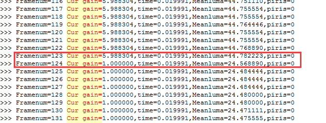
6.8.2 Flickering occurs when exposure changes
There are several reasons why flicker can occur when exposure changes:
(1) The frame number of the gain and time effective moments in the CISExpUpdate module is wrong. Examples of common LOGS are as follows (only key LOG lines per frame are intercepted):
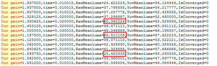
The red frame is marked with the brightness error position, and it can be seen that as the exposure increases or decreases, the corresponding brightness is opposite to the exposure change trend. By observation, it can be seen that the sudden change in luminance occurs in the second frame after both the exposure time and exposure gain change. The change trend of brightness is consistent with the trend of exposure time, so it can be judged that the effective frame number of gain and time is wrong, and the change of exposure time and exposure gain does not take effect at the same time, resulting in a mismatch between brightness and exposure. You can solve this problem by modifying the number of frames in gain and time. The above problems can be reproduced using AE’s syncTest
function, setting two sets of exposures (different exposure gain and exposure time), and making them switch back and forth to see if the LOG can know if it is reproduced.
(2) The brightness oscillation back and forth caused by driving errors cannot converge, often occurs in highlight scenes, common LOG examples are as follows (only intercept the key LOG line of each frame)
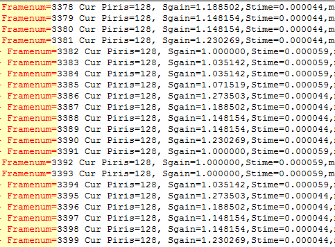
As shown in the figure, it can be observed that the exposure oscillates back and forth between 59ms and 44ms, and looking at the corresponding brightness average of 59ms and 44ms, it will be found that the ratio of brightness and the ratio of exposure of the two has a large gap, and there is a problem with linearity. The first step requires the sensor’s drive detection, where the exposure register value is printed to see if the register value is consistent with the exposure in the log. The above problem can be reproduced using AE’s syncTest function, setting multiple sets of exposures (including the one in question), making them switch back and forth to see if the brightness change corresponding to each frame of exposure in LOG is linear.
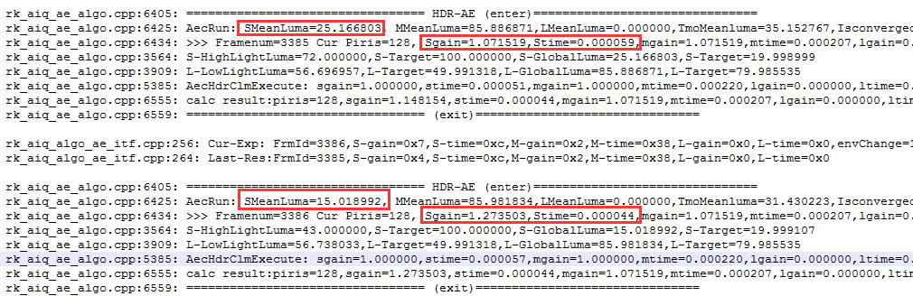
(3) Flickering caused by AE subsequent modules, common LOG examples are as follows (only intercept the key LOG lines of each frame):
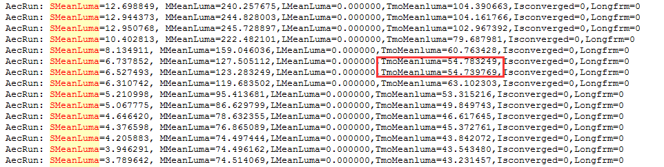
From LOG, it can be seen that during the decline of SMeanLuma and MMeanLuma on the left, the brightness of the output of the TmoMeanluma module has changed, and when this happens, it is necessary to debug the TMO module.
7. AWB
7.1 Overview
The function of the AWB module is to uniformly compensate for the color deviation caused by the color temperature environment and the deviation of the inherent color channel gain of the shooting equipment by changing the gain of the color channel of the shooting equipment, so that the obtained image can correctly reflect the true color of the object.
7.2 Important concepts
Color temperature: The color temperature is defined by the absolute black body, and when the radiation of the light source is exactly the same as the radiation of the absolute black body in the visible area, the temperature of the black body is called the color temperature of the light source.
White balance: Under light sources with different color temperatures, the response of white in the sensor will be bluish or reddish. The white balance algorithm adjusts the intensity of the three color channels R, G, and B to make white appear realistically.
7.3 Description of the feature
The AWB module consists of two parts: WB information statistics and AWB policy control algorithm.
7.4 Feature-level API reference
7.4.1 rk_aiq_uapi2_setWBMode
【Description】 Set the white balance operating mode.
【Grammar】
XCamReturn rk_aiq_uapi2_setWBMode(const rk_aiq_sys_ctx_t* ctx, opMode_t mode);
【Parameters】
| Parameter Name | Description | Input/Output |
|---|---|---|
| sys_ctx | AIQ context pointer | Input |
| mode | White balance operating mode | Input |
【Return Value】
| Return value | Description |
|---|---|
| 0 | Success |
| Non-0 | Failure, see Error Code Table |
【Note】
If set to manual mode, the white balance gain value is controlled by the current manual white balance parameter. If you need to switch manual mode while setting a specific gain value, you can use the rk_aiq_uapi2_setMWBGain interface.
【Requirements】
Header file: rk_aiq_user_api2_imgproc.h
Library file: librkaiq.so
【Example】
Reference sample_awb_module.cpp
7.4.2 rk_aiq_uapi2_getWBMode
【Description】 Gets the white balance operating mode.
【Grammar】
XCamReturn rk_aiq_uapi2_getWBMode(const rk_aiq_sys_ctx_t* ctx, opMode_t *mode);
【Parameters】
| Parameter Name | Description | Input/Output |
|---|---|---|
| sys_ctx | AIQ context pointer | Input |
| mode | White balance operating mode | Output |
【Return Value】
| Return value | Description |
|---|---|
| 0 | Success |
| Non-0 | Failure, see Error Code Table |
【Requirements】
Header file: rk_aiq_user_api2_imgproc.h
Library file: librkaiq.so
【Example】
Reference sample_awb_module.cpp
7.4.3 rk_aiq_uapi2_lockAWB
【Description】 Locks the current white balance parameters.
【Grammar】
XCamReturn rk_aiq_uapi2_lockAWB(const rk_aiq_sys_ctx_t* ctx);
【Parameters】
| Parameter Name | Description | Input/Output |
|---|---|---|
| sys_ctx | AIQ context pointer | Input |
【Return Value】
| Return value | Description |
|---|---|
| 0 | Success |
| Non-0 | Failure, see Error Code Table |
【Requirements】
Header file: rk_aiq_user_api2_imgproc.h
Library file: librkaiq.so
【Example】
Reference sample_awb_module.cpp
7.4.4 rk_aiq_uapi2_unlockAWB
【Description】 Unlock locked white balance parameters.
【Grammar】
XCamReturn rk_aiq_uapi2_unlockAWB(const rk_aiq_sys_ctx_t* ctx);
【Parameters】
| Parameter Name | Description | Input/Output |
|---|---|---|
| sys_ctx | AIQ context pointer | Input |
【Return Value】
| Return value | Description |
|---|---|
| 0 | Success |
| Non-0 | Failure, see Error Code Table |
【Requirements】
Header file: rk_aiq_user_api2_imgproc.h
Library file: librkaiq.so
【Example】
Reference sample_awb_module.cpp
7.4.5 rk_aiq_uapi2_setMWBScene
【Description】 Set the white balance scene.
【Grammar】
 XCamReturn rk_aiq_uapi2_setMWBScene(const rk_aiq_sys_ctx_t* ctx,
 rk_aiq_wb_scene_t scene);
【Parameters】
| Parameter Name | Description | Input/Output |
|---|---|---|
| sys_ctx | AIQ context pointer | Input |
| scene | White balance scene | Input |
【Return Value】
| Return value | Description |
|---|---|
| 0 | Success |
| Non-0 | Failure, see Error Code Table |
【Requirements】
Header file: rk_aiq_user_api2_imgproc.h
Library file: librkaiq.so
【Example】
Reference sample_awb_module.cpp
7.4.6 rk_aiq_uapi2_getMWBScene
【Description】 Get the white balance scene.
【Grammar】
 XCamReturn rk_aiq_uapi2_getMWBScene(const rk_aiq_sys_ctx_t* ctx,
 rk_aiq_wb_scene_t *scene);
【Parameters】
| Parameter Name | Description | Input/Output |
|---|---|---|
| sys_ctx | AIQ context pointer | Input |
| scene | White balance scene | Output |
【Return Value】
| Return value | Description |
|---|---|
| 0 | Success |
| Non-0 | Failure, see Error Code Table |
【Requirements】
Header file: rk_aiq_user_api2_imgproc.h
Library file: librkaiq.so
【Example】
Reference sample_awb_module.cpp
7.4.7 rk_aiq_uapi2_setMWBGain
【Description】 Set the manual white balance gain factor.
【Grammar】
 XCamReturn rk_aiq_uapi2_setMWBGain(const rk_aiq_sys_ctx_t* ctx, rk_aiq_wb_gain_t
 *gain);
【Parameters】
| Parameter Name | Description | Input/Output |
|---|---|---|
| sys_ctx | AIQ context pointer | Input |
| gain | White balance gain factor | Input |
【Return Value】
| Return value | Description |
|---|---|
| 0 | Success |
| Non-0 | Failure, see Error Code Table |
【Requirements】
Header file: rk_aiq_user_api2_imgproc.h
Library file: librkaiq.so
【Example】
Reference sample_awb_module.cpp
7.4.8 rk_aiq_uapi2_getWBGain
【Description】 Gets the white balance gain factor. This function is used for both manual and auto white balance
【Grammar】
 XCamReturn rk_aiq_uapi2_getWBGain(const rk_aiq_sys_ctx_t* ctx, rk_aiq_wb_gain_t
 *gain);
【Parameters】
| Parameter Name | Description | Input/Output |
|---|---|---|
| sys_ctx | AIQ context pointer | Input |
| gain | White balance gain factor | Output |
【Return Value】
| Return value | Description |
|---|---|
| 0 | Success |
| Non-0 | Failure, see Error Code Table |
【Requirements】
Header file: rk_aiq_user_api2_imgproc.h
Library file: librkaiq.so
【Example】
Reference sample_awb_module.cpp
7.4.9 rk_aiq_uapi2_setMWBCT
【Description】 Set the manual white balance color temperature parameter.
【Grammar】
XCamReturn rk_aiq_uapi2_setMWBCT(const rk_aiq_sys_ctx_t* ctx, unsigned int ct);
【Parameters】
| Parameter Name | Description | Input/Output |
|---|---|---|
| sys_ctx | AIQ context pointer | Input |
| ct | White balance color temperature parameters | Input |
【Return Value】
| Return value | Description |
|---|---|
| 0 | Success |
| Non-0 | Failure, see Error Code Table |
【Requirements】
Header file: rk_aiq_user_api2_imgproc.h
Library file: librkaiq.so
【Example】
Reference sample_awb_module.cpp
7.4.10 rk_aiq_uapi2_getWBCT
【Description】 Get the white balance color temperature. This function is used both automatically and manually
【Grammar】
XCamReturn rk_aiq_uapi2_getWBCT(const rk_aiq_sys_ctx_t* ctx, unsigned int *ct);
【Parameters】
| Parameter Name | Description | Input/Output |
|---|---|---|
| sys_ctx | AIQ context pointer | Input |
| ct | White balance color temperature | Output |
【Return Value】
| Return value | Description |
|---|---|
| 0 | Success |
| Non-0 | Failure, see Error Code Table |
【Requirements】
Header file: rk_aiq_user_api2_imgproc.h
Library file: librkaiq.so
【Example】
Reference sample_awb_module.cpp
7.4.11 rk_aiq_uapi2_setAwbGainOffsetAttrib
【Description】 Sets the offset of the auto white balance gain.
【Grammar】
 XCamReturn rk_aiq_uapi2_setAwbGainOffsetAttrib(const rk_aiq_sys_ctx_t* ctx,
 rk_aiq_uapiV2_wb_awb_wbGainOffset_t attr);
【Parameters】
| Parameter Name | Description | Input/Output |
|---|---|---|
| sys_ctx | AIQ context pointer | Input |
| attr | wbgain offset parameter | Input |
【Return Value】
| Return value | Description |
|---|---|
| 0 | Success |
| Non-0 | Failure, see Error Code Table |
【Requirements】
Header file: rk_aiq_user_api2_imgproc.h
Library file: librkaiq.so
【Example】
Reference sample_awb_module.cpp
7.4.12 rk_aiq_uapi2_getAwbGainOffsetAttrib
【Description】 Gets the offset of the auto white balance gain
【Grammar】
 XCamReturn rk_aiq_uapi2_getAwbGainOffsetAttrib(const rk_aiq_sys_ctx_t* ctx,
 CalibDbV2_Awb_gain_offset_cfg_t *attr);
【Parameters】
| Parameter Name | Description | Input/Output |
|---|---|---|
| sys_ctx | AIQ context pointer | Input |
| attr | wbgain offset parameter | Output |
【Return Value】
| Return value | Description |
|---|---|
| 0 | Success |
| Non-0 | Failure, see Error Code Table |
【Requirements】
Header file: rk_aiq_user_api2_imgproc.h
Library file: librkaiq.so
【Example】
Reference sample_awb_module.cpp
7.4.13 rk_aiq_uapi2_setAwbGainAdjustAttrib
【Description】 Sets the tone adjustment parameters in auto white balance mode.
【Grammar】
 XCamReturn rk_aiq_uapi2_setAwbGainAdjustAttrib(const rk_aiq_sys_ctx_t* ctx,
 rk_aiq_uapiV2_wb_awb_wbGainAdjust_t attr);
【Parameters】
| Parameter Name | Description | Input/Output |
|---|---|---|
| sys_ctx | AIQ context pointer | Input |
| attr | White balance tone adjustment parameters | Input |
【Return Value】
| Return value | Description |
|---|---|
| 0 | Success |
| Non-0 | Failure, see Error Code Table |
【Requirements】
Header file: rk_aiq_user_api2_imgproc.h
Library file: librkaiq.so
【Example】
Reference sample_awb_module.cpp
7.4.14 rk_aiq_uapi2_getAwbGainAdjustAttrib
【Description】 Gets the tone adjustment parameters in auto white balance mode.
【Grammar】
 XCamReturn rk_aiq_uapi2_getAwbGainAdjustAttrib(const rk_aiq_sys_ctx_t* ctx,
 rk_aiq_uapiV2_wb_awb_wbGainAdjust_t *attr);
【Parameters】
| Parameter Name | Description | Input/Output |
|---|---|---|
| sys_ctx | AIQ context pointer | Input |
| attr | White balance tone adjustment parameters | Output |
【Return Value】
| Return value | Description |
|---|---|
| 0 | Success |
| Non-0 | Failure, see Error Code Table |
【Requirements】
Header file: rk_aiq_user_api2_imgproc.h
Library file: librkaiq.so
【Example】
Reference sample_awb_module.cpp
7.4.15 rk_aiq_uapi2_setAwbV30AllAttrib
【Description】 Set all parameters supported by the White Balance API.
【Grammar】
 XCamReturn rk_aiq_uapi2_setAwbV30AllAttrib(const rk_aiq_sys_ctx_t* ctx,
 rk_aiq_uapiV2_wbV30_attrib_t attr);
【Parameter】
| Parameter Name | Description | Input/Output |
|---|---|---|
| sys_ctx | AIQ context pointer | input |
| attr | All parameters supported by the White Balance API. | input |
【Return value】
| Return value | Description |
|---|---|
| 0 | succeed |
| Non-0 | Failed, see the error code table for details |
【Demand】
Header files:rk_aiq_user_api2_imgproc.h
Library files:librkaiq.so
【Example】
Refer to sample_awb_module.cpp
7.4.16 rk_aiq_uapi2_getAwbV30AllAttrib
【Description】 Get all the parameters supported by the White Balance API.
【Grammar】
 XCamReturn rk_aiq_uapi2_getAwbV30AllAttrib(const rk_aiq_sys_ctx_t* ctx,
 rk_aiq_uapiV2_wbV30_attrib_t *attr);
【Parameter】
| Parameter Name | Description | Input/Output |
|---|---|---|
| sys_ctx | AIQ context pointer | input |
| attr | wbgain offset parameter | output |
【Return value】
| Return value | Description |
|---|---|
| 0 | succeed |
| Non-0 | Failed, see the error code table for details |
【Demand】
Header files:rk_aiq_user_api2_imgproc.h
Library files:librkaiq.so
【Example】
Refer to sample_awb_module.cpp
7.5 Functional-level API data types
7.5.1 rk_aiq_wb_op_mode_t
【Description】 Defines the white balance operating mode
【Definition】
 typedef enum rk_aiq_wb_op_mode_s {
     RK_AIQ_WB_MODE_INVALID        = 0,
     RK_AIQ_WB_MODE_MANUAL         = 1,
     RK_AIQ_WB_MODE_AUTO           = 2,
     RK_AIQ_WB_MODE_MAX
 } rk_aiq_wb_op_mode_t;
【Member】
| Member Name | Description |
|---|---|
| RK_AIQ_WB_MODE_MANUAL | White balance manual mode |
| RK_AIQ_WB_MODE_AUTO | White balance auto mode |
7.5.2 rk_aiq_wb_mwb_mode_t
【Description】 Defines the manual white balance mode type
【Definition】
 typedef enum rk_aiq_wb_mwb_mode_e {
     RK_AIQ_MWB_MODE_INVAILD              = 0,
     RK_AIQ_MWB_MODE_CCT                  = 1,
     RK_AIQ_MWB_MODE_WBGAIN               = 2,
     RK_AIQ_MWB_MODE_SCENE                = 3,
 } rk_aiq_wb_mwb_mode_t;
【Member】
| Member Name | Description |
|---|---|
| RK_AIQ_MWB_MODE_CCT | Color temperature |
| RK_AIQ_MWB_MODE_WBGAIN | Gain factor |
| RK_AIQ_MWB_MODE_SCENE | Scenario |
7.5.3 rk_aiq_wb_gain_t
【Description】 Define the white balance gain parameters
【Definition】
 typedef struct rk_aiq_wb_gain_s {
     float rgain;
     float grgain;
     float gbgain;
     float bgain;
 } rk_aiq_wb_gain_t;
【Member】
| Member Name | Description |
|---|---|
| rgain | R channel gain |
| grgain | G-channel gain |
| gbgain | GB channel gain |
| bgain | B-channel gain |
7.5.4 rk_aiq_wb_scene_t
【Description】 Define the white balance gain parameters
【Definition】
 typedef enum rk_aiq_wb_scene_e {
     RK_AIQ_WBCT_INCANDESCENT = 0,
     RK_AIQ_WBCT_FLUORESCENT,
     RK_AIQ_WBCT_WARM_FLUORESCENT,
     RK_AIQ_WBCT_DAYLIGHT,
     RK_AIQ_WBCT_CLOUDY_DAYLIGHT,
     RK_AIQ_WBCT_TWILIGHT,
     RK_AIQ_WBCT_SHADE
 } rk_aiq_wb_scene_t;
【Member】
| Member Name | Description |
|---|---|
| RK_AIQ_WBCT_INCANDESCENT | Incandescent lamp |
| RK_AIQ_WBCT_FLUORESCENT | Fluorescent lamps |
| RK_AIQ_WBCT_WARM_FLUORESCENT | Warm fluorescent lamp |
| RK_AIQ_WBCT_DAYLIGHT | Daylight |
| RK_AIQ_WBCT_CLOUDY_DAYLIGHT | Cloudy |
| RK_AIQ_WBCT_TWILIGHT | Twilight |
| RK_AIQ_WBCT_SHADE | Shadow |
7.5.5 rk_aiq_wb_cct_t
【Description】 Define the white balance gain parameters
【Definition】
 typedef struct rk_aiq_wb_cct_s {
     float CCT;
     float CCRI;
 } rk_aiq_wb_cct_t;
【Member】
| Member Name | Description |
|---|---|
| CCT | Correlated color temperature |
| CCRI | Correlation color rendering index |
7.5.6 rk_aiq_wb_mwb_attrib_t
【Description】 Define manual white balance properties
【Definition】
 typedef struct rk_aiq_wb_mwb_attrib_s {
     rk_aiq_wb_mwb_mode_t mode;
     union MWBPara_u {
         rk_aiq_wb_gain_t gain;
         rk_aiq_wb_scene_t scene;
         rk_aiq_wb_cct_t cct;
     } para;
 } rk_aiq_wb_mwb_attrib_t;
【Member】
| Member Name | Description |
|---|---|
| mode | Mode selection |
7.5.7 rk_aiq_uapiV2_wb_awb_wbGainOffset_t
【Description】 Define the auto white balance gain offset
【Definition】
 typedef struct rk_aiq_uapiV2_wb_awb_wbGainOffset_s{
   rk_aiq_uapi_sync_t sync;
   CalibDbV2_Awb_gain_offset_cfg_t gainOffset;
 }rk_aiq_uapiV2_wb_awb_wbGainOffset_t;
【Member】
| Member name | Description |
|---|---|
| sync | Refer to rk_aiq_uapi_sync_t definition in the Overview/API Description section |
| gainOffset | See Description CalibDbV2_Awb_gain_offset_cfg_t Later |
7.5.8 CalibDbV2_Awb_gain_offset_cfg_t
【Description】 Define the auto white balance gain offset
【Definition】
 typedef struct CalibDbV2_Awb_gain_offset_cfg_s{
   bool enable;
   float offset[4];
 }CalibDbV2_Awb_gain_offset_cfg_t;
【Member】
| Member name |
Description |
|---|---|
| enable | The enable switch takes a value of 0 or 1, which means no enable and enable |
| offset | wbgain and offset are added, and the offset range corresponding to R GR GB B channel is determined by the addition of wbgain and offset, and the range after adding wbgain and offset is in the range of [0,8] (ISP21) |
7.5.9 rk_aiq_uapiV2_wb_awb_wbGainAdjust_t
【Description】 Define automatic white balance tonal adjustment parameters
【Definition】
 typedef struct rk_aiq_uapiV2_wb_awb_wbGainAdjustLut_s {
   float lumaValue;
   int ct_grid_num;
   int cri_grid_num;
   float ct_in_range[2];//min,max, equal distance sapmle
   float cri_in_range[2];//min,max
   float *ct_lut_out;//size is ct_grid_num*cri_grid_num
   float *cri_lut_out;
 } rk_aiq_uapiV2_wb_awb_wbGainAdjustLut_t;
 typedef struct rk_aiq_uapiV2_wb_awb_wbGainAdjust_s {
   rk_aiq_uapi_sync_t sync;
   bool enable;
   rk_aiq_uapiV2_wb_awb_wbGainAdjustLut_t *lutAll;
   int lutAll_len;
 } rk_aiq_uapiV2_wb_awb_wbGainAdjust_t;
【Member】
| Member name | Description |
|---|---|
| sync | Refer to rk_aiq_uapi_sync_t definition in the Overview/API Description section |
| enable | The value of tone adjustment enabled is 0 or 1, which means not enabled and enabled |
| lutAll | Different ambient brightness can be configured with different output color temperature tables |
| lutAll_len | Specify the number of temperature tables |
| lutAll.ct_grid_num | The number of sampling points for the color temperature input into the color temperature table is unlimited |
| lutAll.ct_in_range | The range of color temperature entered into the color temperature table is not limited |
| lutAll.cri_grid_num | The number of sampling points for the color rendering index of the input color temperature table is not limited |
| lutAll.cri_in_range | The range of the color rendering index of the input color temperature table is not limited |
| lutAll.ct_out | As shown in the tool interface diagram, the ct value of each dot is from left to right (hue from cold to warm), that is, the value range of CT from small to large is 0-255000 |
| lutAll.cri_out | As shown in the tool interface diagram, the cri of each dot is from bottom to top (hue from purple to green), that is, the CRI from negative number to positive number ** The range of values is not limited |
For more instructions, refer to the WBGain color adjustment chapter in the Rockchip_Color_Optimization_Guide documentation
7.5.10 rk_aiq_uapiV2_wbV30_awb_attrib_t
【Description】 Define auto white balance API parameters
【Definition】
 typedef struct rk_aiq_uapiV2_wbV30_awb_attrib_s {
     rk_aiq_uapiV2_wb_awb_wbGainAdjust_t wbGainAdjust;
     CalibDbV2_Awb_gain_offset_cfg_t wbGainOffset;
 } rk_aiq_uapiV2_wbV30_awb_attrib_t;
【Member】
| Member name | Description |
|---|---|
| wbGainAdjust | Refer to the CalibDbV2_Awb_gain_offset_cfg_t |
| wbGainOffset | Refer to the rk_aiq_uapiV2_wb_awb_wbGainAdjust_t |
| multiWindow | Refer to the rk_aiq_uapiV2_wbV32_awb_mulWindow_t |
7.5.11 rk_aiq_uapiV2_wbV32_attrib_t
【Description】 Define all parameters supported by the White Balance API.
【Definition】
 typedef struct rk_aiq_uapiV2_wbV30_attrib_s {
     rk_aiq_uapi_sync_t sync;
     bool byPass;
     rk_aiq_wb_op_mode_t mode;
     rk_aiq_wb_mwb_attrib_t stManual;
     rk_aiq_uapiV2_wbV30_awb_attrib_t stAuto;
 } rk_aiq_uapiV2_wbV30_attrib_t;
【Member】
| Member name |
Description |
|---|---|
| sync | For rk_aiq_uapi_sync_t description, see **Overview/API Description】 section |
| bypass | The value 0 or 1 0 means to do white balance correction, and the white balance gain used is controlled by the parameter control at the end of the table , 1 means that no white balance correction is performed |
| mode | For automatic or manual white balance mode control parameters, refer to rk_aiq_wb_op_mode_t |
| stManual | For manual white balance parameters, refer to rk_aiq_wb_mwb_attrib_t |
| stAuto | For auto white balance parameters, refer to rk_aiq_uapiV2_wbV21_awb_attrib_t |
7.6 Module-level API reference
7.6.1 rk_aiq_user_api2_awbV30_SetAllAttrib
【Description】 Set all parameters supported by the White Balance API.
【Grammar】
 XCamReturn
 rk_aiq_user_api2_awbV30_SetAllAttrib(const rk_aiq_sys_ctx_t* sys_ctx,
 rk_aiq_uapiV2_wbV30_attrib_t attr);
【Parameters】
| Parameter Name | Description | Input/Output |
|---|---|---|
| sys_ctx | AIQ context pointer | Input |
| attr | All parameters supported by the White Balance API | Output |
【Return Value】
| Return value | Description |
|---|---|
| 0 | Success |
| Non-0 | Failure, see Error Code Table |
【Requirements】
Header files: rk_aiq_user_api2_awb.h, rk_aiq_uapi2_awb_int.h
Library file: librkaiq.so
【Example】
Reference sample_awb_module.cpp
7.6.2 rk_aiq_user_api2_awbV30_GetAllAttrib
【Description】 Get all parameters supported by the White Balance API.
【Grammar】
 XCamReturn
 rk_aiq_user_api2_awbV30_GetAllAttrib(const rk_aiq_sys_ctx_t* sys_ctx,
 rk_aiq_uapiV2_wbV30_attrib_t *attr);
【Parameters】
| Parameter Name | Description | Input/Output |
|---|---|---|
| sys_ctx | AIQ context pointer | Input |
| attr | All parameters supported by the White Balance API | Output |
【Return Value】
| Return value | Description |
|---|---|
| 0 | Success |
| Non-0 | Failure, see Error Code Table |
【Requirements】
Header files: rk_aiq_user_api2_awb.h, rk_aiq_uapi2_awb_int.h
Library file: librkaiq.so
【Example】
Reference sample_awb_module.cpp
7.6.3 rk_aiq_user_api2_awb_GetCCT
【Description】 Get the white balance color temperature. This function is used both automatically and manually
【Grammar】
 XCamReturn
 rk_aiq_user_api2_awb_GetCCT(const rk_aiq_sys_ctx_t* sys_ctx, rk_aiq_wb_cct_t
 *cct);
【Parameters】
| Parameter Name | Description | Input/Output |
|---|---|---|
| sys_ctx | AIQ context pointer | Input |
| cct | Color temperature parameters for white balance | Output |
【Return Value】
| Return value | Description |
|---|---|
| 0 | Success |
| Non-0 | Failure, see Error Code Table |
【Requirements】
Header files: rk_aiq_user_api2_awb.h, rk_aiq_uapi2_awb_int.h
Library file: librkaiq.so
【Example】
Reference sample_awb_module.cpp
7.6.4 rk_aiq_user_api2_awb_QueryWBInfo
【Description】 Get the white balance gain factor, color temperature.
【Grammar】
 XCamReturn
 rk_aiq_user_api2_awb_QueryWBInfo(const rk_aiq_sys_ctx_t* sys_ctx,
 rk_aiq_wb_querry_info_t *wb_querry_info);
【Parameters】
| Parameter Name | Description | Input/Output |
|---|---|---|
| sys_ctx | AIQ context pointer | Input |
| wb_querry_info | Color-dependent status parameters | Output |
【Return Value】
| Return value | Description |
|---|---|
| 0 | Success |
| Non-0 | Failure, see Error Code Table |
【Requirements】
Header files: rk_aiq_user_api2_awb.h, rk_aiq_uapi2_awb_int.h
Library file: librkaiq.so
【Example】
Reference sample_awb_module.cpp
7.6.5 rk_aiq_user_api2_awb_Lock
【Description】 Locks the current white balance parameters.
【Grammar】
 XCamReturn
 rk_aiq_user_api2_awb_Lock(const rk_aiq_sys_ctx_t* sys_ctx);
【Parameters】
| Parameter Name | Description | Input/Output |
|---|---|---|
| sys_ctx | AIQ context pointer | Input |
【Return Value】
| Return value | Description |
|---|---|
| 0 | Success |
| Non-0 | Failure, see Error Code Table |
【Requirements】
Header files: rk_aiq_user_api2_awb.h, rk_aiq_uapi2_awb_int.h
Library file: librkaiq.so
【Example】
Reference sample_awb_module.cpp
7.6.6 rk_aiq_user_api2_awb_Unlock
【Description】 Unlock locked white balance parameters.
【Grammar】
 XCamReturn
 rk_aiq_user_api2_awb_Lock(const rk_aiq_sys_ctx_t* sys_ctx);
【Parameters】
| Parameter Name | Description | Input/Output |
|---|---|---|
| sys_ctx | AIQ context pointer | Input |
【Return Value】
| Return value | Description |
|---|---|
| 0 | Success |
| Non-0 | Failure, see Error Code Table |
【Requirements】
Header files: rk_aiq_user_api2_awb.h, rk_aiq_uapi2_awb_int.h
Library file: librkaiq.so
【Example】
Reference sample_awb_module.cpp
7.6.7 rk_aiq_user_api2_awb_SetWpModeAttrib
【Description】 Set the white balance operating mode.
【Grammar】
 XCamReturn
 rk_aiq_user_api2_awb_SetWpModeAttrib(const rk_aiq_sys_ctx_t* sys_ctx,
 rk_aiq_uapiV2_wb_opMode_t attr);
【Parameters】
| Parameter Name | Description | Input/Output |
|---|---|---|
| sys_ctx | AIQ context pointer | Input |
| attr | White balance operating mode | Output |
【Return Value】
| Return value | Description |
|---|---|
| 0 | Success |
| Non-0 | Failure, see Error Code Table |
【Requirements】
Header files: rk_aiq_user_api2_awb.h, rk_aiq_uapi2_awb_int.h
Library file: librkaiq.so
【Example】
Reference sample_awb_module.cpp
7.6.8 rk_aiq_user_api2_awb_GetWpModeAttrib
【Description】 Gets the white balance operating mode.
【Grammar】
 XCamReturn
 rk_aiq_user_api2_awb_GetWpModeAttrib(const rk_aiq_sys_ctx_t* sys_ctx,
 rk_aiq_uapiV2_wb_opMode_t *attr);
【Parameters】
| Parameter Name | Description | Input/Output |
|---|---|---|
| sys_ctx | AIQ context pointer | Input |
| attr | White balance operating mode | Output |
【Return Value】
| Return value | Description |
|---|---|
| 0 | Success |
| Non-0 | Failure, see Error Code Table |
【Requirements】
Header files: rk_aiq_user_api2_awb.h, rk_aiq_uapi2_awb_int.h
Library file: librkaiq.so
【Example】
Reference sample_awb_module.cpp
7.6.9 rk_aiq_user_api2_awb_SetMwbAttrib
【Description】 Set manual white balance parameters.
【Grammar】
 XCamReturn
 rk_aiq_user_api2_awb_SetMwbAttrib(const rk_aiq_sys_ctx_t* sys_ctx,
 rk_aiq_wb_mwb_attrib_t attr);
【Parameters】
| Parameter Name | Description | Input/Output |
|---|---|---|
| sys_ctx | AIQ context pointer | Input |
| attr | Manual white balance parameters | Input |
【Return Value】
| Return value | Description |
|---|---|
| 0 | Success |
| Non-0 | Failure, see Error Code Table |
【Requirements】
Header files: rk_aiq_user_api2_awb.h, rk_aiq_uapi2_awb_int.h
Library file: librkaiq.so
【Example】
Reference sample_awb_module.cpp
7.6.10 rk_aiq_user_api2_awb_GetMwbAttrib
【Description】 Set manual white balance parameters.
【Grammar】
 XCamReturn
 rk_aiq_user_api2_awb_SetMwbAttrib(const rk_aiq_sys_ctx_t* sys_ctx,
 rk_aiq_wb_mwb_attrib_t attr);
【Parameters】
| Parameter Name | Description | Input/Output |
|---|---|---|
| sys_ctx | AIQ context pointer | Input |
| attr | Manual white balance parameters | Input |
【Return Value】
| Return value | Description |
|---|---|
| 0 | Success |
| Non-0 | Failure, see Error Code Table |
【Requirements】
Header files: rk_aiq_user_api2_awb.h, rk_aiq_uapi2_awb_int.h
Library file: librkaiq.so
【Example】
Reference sample_awb_module.cpp
7.6.11 rk_aiq_user_api2_awb_SetWbGainAdjustAttrib
【Description】 Sets the tone adjustment parameters in auto white balance mode.
【Grammar】
 XCamReturn
 rk_aiq_user_api2_awb_SetWbGainAdjustAttrib(const rk_aiq_sys_ctx_t* sys_ctx,
 rk_aiq_uapiV2_wb_awb_wbGainAdjust_t attr);
【Parameters】
| Parameter Name | Description | Input/Output |
|---|---|---|
| sys_ctx | AIQ context pointer | Input |
| attr | Tone adjustment parameters | Input |
【Return Value】
| Return value | Description |
|---|---|
| 0 | Success |
| Non-0 | Failure, see Error Code Table |
【Requirements】
Header files: rk_aiq_user_api2_awb.h, rk_aiq_uapi2_awb_int.h
Library file: librkaiq.so
【Example】
Reference sample_awb_module.cpp
7.6.12 rk_aiq_user_api2_awb_GetWbGainAdjustAttrib
【Description】 Gets the tone adjustment parameters in auto white balance mode.
【Grammar】
 XCamReturn
 rk_aiq_user_api2_awb_GetWbGainAdjustAttrib(const rk_aiq_sys_ctx_t* sys_ctx,
 rk_aiq_uapiV2_wb_awb_wbGainAdjust_t *attr);
【Parameters】
| Parameter Name | Description | Input/Output |
|---|---|---|
| sys_ctx | AIQ context pointer | Input |
| attr | Tone adjustment parameters | Input |
【Return Value】
| Return value | Description |
|---|---|
| 0 | Success |
| Non-0 | Failure, see Error Code Table |
【Requirements】
Header files: rk_aiq_user_api2_awb.h, rk_aiq_uapi2_awb_int.h
Library file: librkaiq.so
【Example】
Reference sample_awb_module.cpp
7.6.13 rk_aiq_user_api2_awb_SetWbGainOffsetAttrib
【Description】 Sets the offset of the auto white balance gain
【Grammar】
 XCamReturn
 rk_aiq_user_api2_awb_SetWbGainOffsetAttrib(const rk_aiq_sys_ctx_t* sys_ctx,
 rk_aiq_uapiV2_wb_awb_wbGainOffset_t attr);
【Parameters】
| Parameter Name | Description | Input/Output |
|---|---|---|
| sys_ctx | AIQ context pointer | Input |
| attr | Tone adjustment parameters | Input |
【Return Value】
| Return value | Description |
|---|---|
| 0 | Success |
| Non-0 | Failure, see Error Code Table |
【Requirements】
Header files: rk_aiq_user_api2_awb.h, rk_aiq_uapi2_awb_int.h
Library file: librkaiq.so
【Example】
Reference sample_awb_module.cpp
7.6.14 rk_aiq_user_api2_awb_GetWbGainOffsetAttrib
【Description】 Gets the offset of the auto white balance gain
【Grammar】
 XCamReturn
 rk_aiq_user_api2_awb_GetWbGainOffsetAttrib(const rk_aiq_sys_ctx_t* sys_ctx,
 rk_aiq_uapiV2_wb_awb_wbGainOffset_t *attr);
【Parameters】
| Parameter Name | Description | Input/Output |
|---|---|---|
| sys_ctx | AIQ context pointer | Input |
| attr | Tone adjustment parameters | Input |
【Return Value】
| Return value | Description |
|---|---|
| 0 | Success |
| Non-0 | Failure, see Error Code Table |
【Requirements】
Header files: rk_aiq_user_api2_awb.h, rk_aiq_uapi2_awb_int.h
Library file: librkaiq.so
【Example】
Reference sample_awb_module.cpp
7.7 Module-level API data types
7.7.1 rk_aiq_wb_querry_info_t
【Description】 Define white balance query information
【Definition】
 typedef struct rk_aiq_wb_querry_info_s {
     rk_aiq_wb_gain_t gain;
     rk_aiq_wb_cct_t cctGloabl;
     bool awbConverged;
     uint32_t LVValue;
 } rk_aiq_wb_querry_info_t;
【Member】
| Member Name | Description |
|---|---|
| gain | Gain |
| cctGloabl | Global Color Temperature Parameter |
| LVValue | Related ambient brightness |
7.7.2 rk_aiq_wb_op_mode_t
【Description】 Defines the white balance operating mode
【Definition】
 typedef struct rk_aiq_uapiV2_wb_opMode_s {
   rk_aiq_uapi_sync_t sync;
   rk_aiq_wb_op_mode_t mode;
 } rk_aiq_uapiV2_wb_opMode_t;
【Member】
| Member Name | Description |
|---|---|
| sync | For rk_aiq_uapi_sync_t description, see **Overview/API Description】 section |
| mode | Refer to rk_aiq_wb_op_mode_t Description |
7.7.3 rk_aiq_wb_mwb_attrib_t
【Description】 Define manual white balance properties
【Definition】
 typedef struct rk_aiq_wb_mwb_attrib_s {
      rk_aiq_uapi_sync_t sync;
     rk_aiq_wb_mwb_mode_t mode;
     union MWBPara_u {
         rk_aiq_wb_gain_t gain;
         rk_aiq_wb_scene_t scene;
         rk_aiq_wb_cct_t cct;
     } para;
 } rk_aiq_wb_mwb_attrib_t;
【Member】
| Member Name | Description |
|---|---|
| sync | For rk_aiq_uapi_sync_t definitions, see Overview/API Description section |
| mode | Mode selection |
| para | Parameter configuration for the mode |
8. AF
8.1 Overview
The function of the AF module refers to the process of adjusting the camera lens so that the image of the subject is clear.
8.2 Description of the feature
The AF module consists of two parts: AF information statistics and AF control algorithm. The figure below shows the block diagram of the AF information statistics module
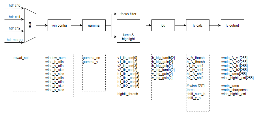
Among them, ch0/ch1/ch2 corresponds to the S/M/L frame in HDR mode, and debayer is the composite frame in HDR mode.
The output of windowA mainly contains 15*15 V1/V2/H1/H2 FV information, brightness information and highlight count.
The output of windowB mainly contains an FV information, brightness information, and highlight count.
8.3 Development of userAF algorithms
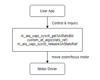
Reference code location: sdk: external/camera_engine_rkaiq/rkisp_demo/demo/af_algo_demo
8.4 Feature-level API reference
8.4.1 rk_aiq_uapi2_setFocusMode
【Description】 :Configure the focus mode.
【Grammar】
XCamReturn rk_aiq_uapi2_setFocusMode(const rk_aiq_sys_ctx_t* ctx, opMode_t mode);
【Parameters】
| Parameter Name | Description | Input/Output |
|---|---|---|
| sys_ctx | AIQ context pointer | Input |
| mode | Focus mode | Input |
【Return Value】
| Return value | Description |
|---|---|
| 0 | Success |
| Non-0 | Failure, see Error Code Table |
【Requirements】
Header file: rk_aiq_user_api2_imgproc.h
Library file: librkaiq.so
8.4.2 rk_aiq_uapi2_getFocusMode
【Description】: Gets the current focus mode.
【Grammar】
 XCamReturn rk_aiq_uapi2_getFocusMode(const rk_aiq_sys_ctx_t* ctx, opMode_t
 *mode);
【Parameters】
| Parameter Name | Description | Input/Output |
|---|---|---|
| sys_ctx | AIQ context pointer | Input |
| mode | Focus mode | Output |
【Return Value】
| Return value | Description |
|---|---|
| 0 | Success |
| Non-0 | Failure, see Error Code Table |
【Requirements】
Header file: rk_aiq_user_api2_imgproc.h
Library file: librkaiq.so
8.4.3 rk_aiq_uapi2_setFocusWin
【Description】 Set the autofocus window.
【Grammar】
XCamReturn rk_aiq_uapi2_setFocusWin(const rk_aiq_sys_ctx_t* ctx, paRect_t *rect);
【Parameters】
| Parameter Name |
Description | Input/Output |
|---|---|---|
| sys_ctx | AIQ context pointer | Input |
| rect | Focus window, the value range is determined by the sensor input size |
Input |
【Return Value】
| Return value | Description |
|---|---|
| 0 | Success |
| Non-0 | Failure, see Error Code Table |
【Requirements】
Header file: rk_aiq_user_api2_imgproc.h
Library file: librkaiq.so
8.4.4 rk_aiq_uapi2_getFocusWin
【Description】 Set the autofocus window.
【Grammar】
XCamReturn rk_aiq_uapi2_getFocusWin(const rk_aiq_sys_ctx_t* ctx, paRect_t *rect);
【Parameters】
| Parameter Name | Description | Input/Output |
|---|---|---|
| sys_ctx | AIQ context pointer | Input |
| rect | Focus window | Output |
【Return Value】
| Return value | Description |
|---|---|
| 0 | Success |
| Non-0 | Failure, see Error Code Table |
【Requirements】
Header file: rk_aiq_user_api2_imgproc.h
Library file: librkaiq.so
8.4.5 rk_aiq_uapi2_lockFocus
【Description】 :Lock autofocus, focus pause action.
【Grammar】
XCamReturn rk_aiq_uapi2_lockFocus(const rk_aiq_sys_ctx_t* ctx);
【Parameters】
| Parameter Name | Description | Input/Output |
|---|---|---|
| sys_ctx | AIQ context pointer | Input |
【Return Value】
| Return value | Description |
|---|---|
| 0 | Success |
| Non-0 | Failure, see Error Code Table |
【Requirements】
Header file: rk_aiq_user_api2_imgproc.h
Library file: librkaiq.so
8.4.6 rk_aiq_uapi2_unlockFocus
【Description】 Unlock autofocus, focus continues action.
【Grammar】
XCamReturn rk_aiq_uapi2_unlockFocus(const rk_aiq_sys_ctx_t* ctx);
【Parameters】
| Parameter Name | Description | Input/Output |
|---|---|---|
| sys_ctx | AIQ context pointer | Input |
【Return Value】
| Return value | Description |
|---|---|
| 0 | Success |
| Non-0 | Failure, see Error Code Table |
【Requirements】
Header file: rk_aiq_user_api2_imgproc.h
Library file: librkaiq.so
8.4.7 rk_aiq_uapi2_oneshotFocus
【Description】 Trigger a single focus, after the focus is completed, the focus will not continue.
【Grammar】
XCamReturn rk_aiq_uapi2_oneshotFocus(const rk_aiq_sys_ctx_t* ctx);
【Parameters】
| Parameter Name | Description | Input/Output |
|---|---|---|
| sys_ctx | AIQ context pointer | Input |
【Return Value】
| Return value | Description |
|---|---|
| 0 | Success |
| Non-0 | Failure, see Error Code Table |
【Requirements】
Header file: rk_aiq_user_api2_imgproc.h
Library file: librkaiq.so
8.4.8 rk_aiq_uapi2_manualTrigerFocus
【Description】 Manually trigger focus, after the focus is completed, continue to monitor whether the picture is blurry, if the picture is blurry, perform focus again.
【Grammar】
XCamReturn rk_aiq_uapi2_manualTrigerFocus(const rk_aiq_sys_ctx_t* ctx);
【Parameters】
| Parameter Name | Description | Input/Output |
|---|---|---|
| sys_ctx | AIQ context pointer | Input |
【Return Value】
| Return value | Description |
|---|---|
| 0 | Success |
| Non-0 | Failure, see Error Code Table |
【Requirements】
Header file: rk_aiq_user_api2_imgproc.h
Library file: librkaiq.so
8.4.9 rk_aiq_uapi2_trackingFocus
【Description】 Continue to monitor whether the picture is blurry, if the picture is blurry, perform focus again, generally use after rk_aiq_uapi2_oneshotFocus.
【Grammar】
XCamReturn rk_aiq_uapi2_trackingFocus(const rk_aiq_sys_ctx_t* ctx);
【Parameters】
| Parameter Name | Description | Input/Output |
|---|---|---|
| sys_ctx | AIQ context pointer | Input |
【Return Value】
| Return value | Description |
|---|---|
| 0 | Success |
| Non-0 | Failure, see Error Code Table |
【Requirements】
Header file: rk_aiq_user_api2_imgproc.h
Library file: librkaiq.so
8.4.10 rk_aiq_uapi2_getSearchResult
【Description】 Get the focus result.
【Grammar】
 XCamReturn rk_aiq_uapi2_getSearchResult(const rk_aiq_sys_ctx_t* ctx,
 rk_aiq_af_result_t* result);
【Parameters】
| Parameter Name |
Description | Input/Output |
|---|---|---|
| sys_ctx | AIQ context pointer | Input |
| result | For focusing results, refer to the description of the structure rk_aiq_af_result_t |
Output |
【Return Value】
| Return value | Description |
|---|---|
| 0 | Success |
| Non-0 | Failure, see Error Code Table |
【Requirements】
Header file: rk_aiq_user_api2_imgproc.h
Library file: librkaiq.so
8.4.11 rk_aiq_uapi2_getZoomRange
【Description】Gets the zoom range value, which is used to limit the zoom code parameters rk_aiq_uapi_setOpZoomPosition input.
【Grammar】
 XCamReturn rk_aiq_uapi2_getZoomRange(const rk_aiq_sys_ctx_t* ctx,
 rk_aiq_af_zoomrange* range);
【Parameters】
| Parameter Name | Description | Input/Output |
|---|---|---|
| sys_ctx | AIQ context pointer | Input |
| range | Zoom movable range, refer to structure rk_aiq_af_zoomrange | Output |
【Return Value】
| Return value | Description |
|---|---|
| 0 | Success |
| Non-0 | Failure, see Error Code Table |
【Requirements】
Header file: rk_aiq_user_api2_imgproc.h
Library file: librkaiq.so
8.4.12 rk_aiq_uapi2_setOpZoomPosition
【Description】 Set zoom position, modify zoom position.
【Grammar】
XCamReturn rk_aiq_uapi2_setOpZoomPosition(const rk_aiq_sys_ctx_t* ctx, int pos);
【Parameters】
| Parameter Name |
Description | Input/Output |
|---|---|---|
| sys_ctx | AIQ context pointer | Input |
| pos | zoom position, the value range is determined by rk_aiq_uapi2_getZoomRange |
Input |
【Return Value】
| Return value | Description |
|---|---|
| 0 | Success |
| Non-0 | Failure, see Error Code Table |
【Requirements】
Header file: rk_aiq_user_api2_imgproc.h
Library file: librkaiq.so
8.4.13 rk_aiq_uapi2_getOpZoomPosition
【Description】 Get the zoom location.
【Grammar】
XCamReturn rk_aiq_uapi2_getOpZoomPosition(const rk_aiq_sys_ctx_t* ctx, int *pos);
【Parameters】
| Parameter Name | Description | Input/Output |
|---|---|---|
| sys_ctx | AIQ context pointer | Input |
| pos | zoom position | Output |
【Return Value】
| Return value | Description |
|---|---|
| 0 | Success |
| Non-0 | Failure, see Error Code Table |
【Requirements】
Header file: rk_aiq_user_api2_imgproc.h
Library file: librkaiq.so
8.4.14 rk_aiq_uapi2_endOpZoomChange
【Description】 End the setting of the zoom device position, call after the rk_aiq_uapi_setOpZoomPosition, and perform the focus action after being called.
【Grammar】
XCamReturn rk_aiq_uapi2_endOpZoomChange(const rk_aiq_sys_ctx_t* ctx);
【Parameters】
| Parameter Name | Description | Input/Output |
|---|---|---|
| sys_ctx | AIQ context pointer | Input |
【Return Value】
| Return value | Description |
|---|---|
| 0 | Success |
| Non-0 | Failure, see Error Code Table |
【Requirements】
Header file: rk_aiq_user_api2_imgproc.h
Library file: librkaiq.so
8.4.15 rk_aiq_uapi2_getFocusRange
【Description】 Gets the focus range value, which is used to limit the focus code parameter rk_aiq_uapi_setFocusPosition input.
【Grammar】
 XCamReturn rk_aiq_uapi2_getFocusRange(const rk_aiq_sys_ctx_t* ctx,
 rk_aiq_af_focusrange* range);
【Parameters】
| Parameter Name | Description | Input/Output |
|---|---|---|
| sys_ctx | AIQ context pointer | Input |
| range | Focus movable range, refer to the structure rk_aiq_af_focusrange | Output |
【Return Value】
| Return value | Description |
|---|---|
| 0 | Success |
| Non-0 | Failure, see Error Code Table |
【Requirements】
Header file: rk_aiq_user_api2_imgproc.h
Library file: librkaiq.so
8.4.16 rk_aiq_uapi2_setFocusPosition
【Description】 Set the focus position in manual focus mode.
【Grammar】
 XCamReturn rk_aiq_uapi2_setFocusPosition(const rk_aiq_sys_ctx_t* ctx, unsigned
 short code);
【Parameters】
| Parameter Name |
Description | Input/Output |
|---|---|---|
| sys_ctx | AIQ context pointer | Input |
| code | Focus code value, the value range is determined by rk_aiq_uapi2_getFocusRange |
Input |
【Return Value】
| Return value | Description |
|---|---|
| 0 | Success |
| Non-0 | Failure, see Error Code Table |
【Requirements】
Header file: rk_aiq_user_api2_imgproc.h
Library file: librkaiq.so
8.4.17 rk_aiq_uapi2_getFocusPosition
【Description】 Gets the current focus position.
【Grammar】
 XCamReturn rk_aiq_uapi2_getFocusPosition(const rk_aiq_sys_ctx_t* ctx, unsigned
 short *code);
【Parameters】
| Parameter Name | Description | Input/Output |
|---|---|---|
| sys_ctx | AIQ context pointer | Input |
| code | Focus code value | Output |
【Return Value】
| Return value | Description |
|---|---|
| 0 | Success |
| Non-0 | Failure, see Error Code Table |
【Requirements】
Header file: rk_aiq_user_api2_imgproc.h
Library file: librkaiq.so
8.4.18 rk_aiq_uapi2_startZoomCalib
【Description】 Perform electric motor module correction.
【Grammar】
XCamReturn rk_aiq_uapi2_startZoomCalib(const rk_aiq_sys_ctx_t* ctx);
【Parameters】
| Parameter Name | Description | Input/Output |
|---|---|---|
| sys_ctx | AIQ context pointer | Input |
【Return Value】
| Return value | Description |
|---|---|
| 0 | Success |
| Non-0 | Failure, see Error Code Table |
【Requirements】
Header file: rk_aiq_user_api2_imgproc.h
Library file: librkaiq.so
8.4.19 rk_aiq_uapi2_resetZoom
【Description】 Perform an electric motor module reset.
【Grammar】
XCamReturn rk_aiq_uapi2_resetZoom(const rk_aiq_sys_ctx_t* ctx);
【Parameters】
| Parameter Name | Description | Input/Output |
|---|---|---|
| sys_ctx | AIQ context pointer | Input |
【Return Value】
| Return value | Description |
|---|---|
| 0 | Success |
| Non-0 | Failure, see Error Code Table |
【Requirements】
Header file: rk_aiq_user_api2_imgproc.h
Library file: librkaiq.so
8.5 Functional-level API data types
8.5.1 opMode_t
【Description】 Define the AF information statistics working mode
【Definition】
 typedef enum opMode_e {
     OP_AUTO   = 0,
     OP_MANUAL = 1,
     OP_SEMI_AUTO = 2,
     OP_INVAL
 } opMode_t;
【Member】
| Member Name | Description |
|---|---|
| OP_AUTO | Autofocus mode, running the built-in AF algorithm |
| OP_MANUAL | Manual focus mode, stop the built-in AF algorithm |
| OP_SEMI_AUTO | Semi-autofocus mode, set zoom position API call to perform an autofocus |
8.5.2 rk_aiq_af_zoomrange
【Description】 Define the zoom value range
【Definition】
 typedef struct {
     int min_pos;
     int max_pos;
     float min_fl;
     float max_fl;
 } rk_aiq_af_zoomrange;
【Member】
| Member Name | Description |
|---|---|
| min_pos | zoom minimum |
| max_pos | zoommax |
| min_fl | Minimum focal length |
| max_fl | Maximum focal length |
8.5.3 rk_aiq_af_focusrange
【Description】 Define the focus value range
【Definition】
 typedef struct {
     int min_pos;
     int max_pos;
 } rk_aiq_af_focusrange;
【Member】
| Member Name | Description |
|---|---|
| min_pos | Focus Minimum |
| max_pos | Focus Max |
8.5.4 rk_aiq_af_result_t
【Description】 Define AF search results
【Definition】
 typedef enum rk_aiq_af_sec_stat_e
 {
     RK_AIQ_AF_SEARCH_INVAL   = 0,
     RK_AIQ_AF_SEARCH_RUNNING = 1,
     RK_AIQ_AF_SEARCH_END     = 2
 } rk_aiq_af_sec_stat_t;
 typedef struct {
     rk_aiq_af_sec_stat_t stat;
     int32_t final_pos;
 } rk_aiq_af_result_t;
【Member】
| Member Name | Description |
|---|---|
| stat | Focus Status |
| final_pos | Final focus location |
8.6 Module-level API reference
8.6.1 rk_aiq_user_api2_af_SetAttrib
【Description】 Set the focus properties.
【Grammar】
 XCamReturn
 rk_aiq_user_api2_af_SetAttrib(const rk_aiq_sys_ctx_t* sys_ctx, rk_aiq_af_attrib_t
 attr);
【Parameters】
| Parameter Name | Description | Input/Output |
|---|---|---|
| sys_ctx | AIQ context pointer | Input |
| attr | Parameter properties of focus | Input |
【Return Value】
| Return value | Description |
|---|---|
| 0 | Success |
| Non-0 | Failure, see Error Code Table |
【Requirements】
Header file: rk_aiq_user_api2_af.h
Library file: librkaiq.so
8.6.2 rk_aiq_user_api2_af_GetAttrib
【Description】 Gets the focus properties.
【Grammar】
 XCamReturn
 rk_aiq_user_api2_af_GetAttrib(const rk_aiq_sys_ctx_t* sys_ctx, rk_aiq_af_attrib_t
 *attr);
【Parameters】
| Parameter Name | Description | Input/Output |
|---|---|---|
| sys_ctx | AIQ context pointer | Input |
| attr | Parameter properties of focus | Output |
【Return Value】
| Return value | Description |
|---|---|
| 0 | Success |
| Non-0 | Failure, see Error Code Table |
【Requirements】
Header file: rk_aiq_user_api2_af.h
Library file: librkaiq.so
8.7 Module-level API data types
8.7.1 RKAIQ_AF_MODE
【Description】 Defines the focus operating mode
【Definition】
 typedef enum _RKAIQ_AF_MODE
 {
     RKAIQ_AF_MODE_NOT_SET = -1,
     RKAIQ_AF_MODE_AUTO,
     RKAIQ_AF_MODE_MACRO,
     RKAIQ_AF_MODE_INFINITY,
     RKAIQ_AF_MODE_FIXED,
     RKAIQ_AF_MODE_EDOF,
     RKAIQ_AF_MODE_CONTINUOUS_VIDEO,
     RKAIQ_AF_MODE_CONTINUOUS_PICTURE,
     RKAIQ_AF_MODE_ONESHOT_AFTER_ZOOM,
 } RKAIQ_AF_MODE;
【Member】
| Member Name | Description |
|---|---|
| RKAIQ_AF_MODE_NOT_SET | The focus mode is not set |
| RKAIQ_AF_MODE_AUTO | Autofocus mode |
| RKAIQ_AF_MODE_MACRO | Macro focus mode |
| RKAIQ_AF_MODE_INFINITY | Long Focus Mode |
| RKAIQ_AF_MODE_FIXED | Fixed focus mode |
| RKAIQ_AF_MODE_EDOF | Depth of field focus mode |
| RKAIQ_AF_MODE_CONTINUOUS_VIDEO | Smooth continuous focus mode |
| RKAIQ_AF_MODE_CONTINUOUS_PICTURE | Fast continuous focus mode |
| RKAIQ_AF_MODE_ONESHOT_AFTER_ZOOM | Semi-autofocus mode, set zoom position call, automatically trigger a focus |
8.7.2 RKAIQ_AF_HWVER
【Description】 Defines the focus operating mode
【Definition】
 typedef enum _RKAIQ_AF_HWVER
 {
     RKAIQ_AF_HW_V20 = 0,
     RKAIQ_AF_HW_V30,
     RKAIQ_AF_HW_VMAX
 } RKAIQ_AF_HWVER;
【Member】
| Member Name | Description |
|---|---|
| RKAIQ_AF_HW_V20 | AF hardware version 2.0 |
| RKAIQ_AF_HW_V30 | AF hardware version 3.0 |
8.7.3 rk_aiq_af_algo_meas_v30_t
【Description】 Define the AF information statistics working mode
【Definition】
 typedef struct {
     unsigned char af_en;
     unsigned char rawaf_sel;
     unsigned char gamma_en;
     unsigned char gaus_en;
     unsigned char v1_fir_sel;
     unsigned char hiir_en;
     unsigned char viir_en;
     unsigned char v1_fv_outmode;    // 0 square, 1 absolute
     unsigned char v2_fv_outmode;    // 0 square, 1 absolute
     unsigned char h1_fv_outmode;    // 0 square, 1 absolute
     unsigned char h2_fv_outmode;    // 0 square, 1 absolute
     unsigned char ldg_en;
     unsigned char accu_8bit_mode;   //fix to 1
     unsigned char ae_mode;
     unsigned char y_mode;           //fix to 0
     unsigned char line_en[RKAIQ_RAWAF_LINE_NUM];
     unsigned char line_num[RKAIQ_RAWAF_LINE_NUM];
     unsigned char window_num;
     unsigned short wina_h_offs;
     unsigned short wina_v_offs;
     unsigned short wina_h_size;
     unsigned short wina_v_size;
     unsigned short winb_h_offs;
     unsigned short winb_v_offs;
     unsigned short winb_h_size;
     unsigned short winb_v_size;
     unsigned short gamma_y[RKAIQ_RAWAF_GAMMA_NUM];
     // [old version param]
     unsigned short thres;
     unsigned char shift_sum_a;
     unsigned char shift_sum_b;
     unsigned char shift_y_a;
     unsigned char shift_y_b;
     /**********[Vertical IIR (v1 & v2)]************/
     short v1_iir_coe[9];
     short v1_fir_coe[3];
     short v2_iir_coe[3];
     short v2_fir_coe[3];
     /**********[Horizontal IIR (h1 & h2)]************/
     short h1_iir1_coe[6];
     short h2_iir1_coe[6];
     short h1_iir2_coe[6];
     short h2_iir2_coe[6];
     /**********[Focus value statistic param]**********/
     // level depended gain
     // input8 lumi, output8bit gain
     unsigned char h_ldg_lumth[2];    //luminance thresh
     unsigned char h_ldg_gain[2];     //gain for [minLum,maxLum]
     unsigned short h_ldg_gslp[2];    //[slope_low,-slope_high]
     unsigned char v_ldg_lumth[2];
     unsigned char v_ldg_gain[2];
     unsigned short v_ldg_gslp[2];
     // coring
     unsigned short v_fv_thresh;
     unsigned short h_fv_thresh;
     // left shift, more needed if outmode=square
     unsigned char v1_fv_shift; //only for sel1
     unsigned char v2_fv_shift;
     unsigned char h1_fv_shift;
     unsigned char h2_fv_shift;
     /**********[High light]**********/
     unsigned short highlit_thresh;
 }  rk_aiq_af_algo_meas_v30_t;
【Member】
| Member Name | Description |
|---|---|
| af_en | Whether AF information statistics are enabled, 0 is off, 1 is on |
| rawaf_sel | Select the channel of AF information statistics, the value range is 0-3, the long/medium/short/synthetic frame channel selection corresponding to HDR mode, the general AF selection medium frame channel, the non-HDR mode is set to 0, and the HDR mode is set to 1 |
| gamma_en | Gamma module enables switch, 0 is off, 1 is on |
| gaus_en | The setting needs to be fixed to 1 |
| v1_fir_sel | The setting needs to be fixed to 1 |
| hiir_en | H1/H2 channel enable switch, 0 is off, 1 is on |
| viir_en | V1/V2 channel enable switch, 0 is off and 1 is on. Note that when the gamma_en is opened, the viir_en must be set to 1 |
| v1_fv_outmode | V1 channel FV output mode selection, 0 for squared mode, 1 for absolute value mode |
| v2_fv_outmode | V2 channel FV output mode selection, 0 for squared mode, 1 for absolute value mode |
| ldg_en | LDG function enable switch, 0 is off, 1 is on |
| accu_8bit_mode | The setting needs to be fixed to 1 |
| ae_mode | When the ae_mode is set to 1, RAWAF enables 15x15 brightness averaging statistics, multiplexing the logic of the RAWAE_BIG module |
| y_mode | The setting needs to be fixed to 0 |
| sobel_sel | The setting needs to be fixed to 0 |
| v_dnscl_mode | Wide and narrow band mode selection, set according to the output of the AF filter coefficient generation tool |
| from_awb | The AF statistics input is obtained from AWB |
| from_ynr | The AF statistics input is obtained from YNR |
| ae_config_use | Fixed configuration 0 |
| line_en | Currently not effective |
| line_num | Currently not effective |
| window_num | The number of windows in effect, when the window_num is 1, WinA (main window) takes effect; When the window_num is 2, wina (main window) and winb (independent window) take effect |
| wina_h_offs | The horizontal coordinate of the first pixel in the upper left corner of WinA (main window), which must be greater than or equal to 2 |
| wina_v_offs | The vertical coordinate of the first pixel in the upper-left corner of wina (main window), which must be greater than or equal to 1 |
| Member Name | Description |
|---|---|
| wina_h_size | the window width of Wina (main window), which must be less than the image width -2-wina_h_offs; The value must also be a multiple of 15; |
| wina_v_size | the window height of Wina (main window), which must be less than the image height -2-wina_v_offs; The value must also be a multiple of 15; |
| winb_h_offs | The horizontal coordinate of the first pixel in the upper-left corner of winb (separate window), which must be greater than or equal to 2 |
| winb_v_offs | The vertical coordinate of the first pixel in the upper-left corner of winb (stand-alone window), which must be greater than or equal to 1 |
| winb_h_size | The window width of winb (independent window), which must be less than the image width -2-wina_h_offs |
| winb_v_size | The window height of winb (independent window), which must be less than the image height -2-wina_v_offs |
| gamma_y | The y value of the gamma table, the value range is 0-1023; The x-coordinate segment is 0 to 1023: 16 16 16 16 32 32 32 32 64 64 64 128 128 128 128 128 |
| thres | The AF statistical threshold of win b (independent window), when the calculated fv value is less than this value, the fv value is changed to 0, which can reduce the influence of noise, and the value range is 0-0xFFFF |
| shift_sum_a | Currently unavailable, fixed setting to 0 |
| shift_y_a | Currently unavailable, fixed setting to 0 |
| v1_iir_coe[9] | The 3X3 IIR coefficient for the V1 channel is set according to the output of the AF Filter Factor Generation tool |
| v1_fir_coe[3] | The 1x3 FIR factor for the V1 channel is set according to the output of the AF filter coefficient generation tool |
| v2_iir_coe[3] | The 1x3 IIR coefficient for the V2 channel is set according to the output of the AF filter coefficient generation tool |
| v2_fir_coe[3] | The 1x3 FIR factor for the V2 channel is set according to the output of the AF Filter Factor Generation tool |
| h1_iir1_coe[6] | The 1X6 IIR1 coefficient for the H1 channel, set according to the output of the AF Filter Factor Generation tool |
| h2_iir1_coe[6] | The 1X6 IIR1 coefficient for the H2 channel is set according to the output of the AF Filter Factor Generation tool |
| h1_iir2_coe[6] | The 1X6 IIR2 coefficient for the H1 channel is set according to the output of the AF Filter Factor Generation tool |
| h2_iir2_coe[6] | 1X6 IIR2 coefficient for H2 channel, set according to the output of the AF filter coefficient generation tool |
| Member Name | Description |
|---|---|
| h_ldg_lumth[2] | The brightness threshold coefficient of the ldg module used for H1/H2 channels, 0 is set for the left dark area, 1 is set for the right highlight area, and the value range is 0~255 |
| h_ldg_gain[2] | The minimum gain value of the ldg module used for H1/H2 channels, 0 is the left dark area setting, 1 is the right highlight area setting, the value range is 0~255 |
| h_ldg_gslp[2] | The slope coefficient of the ldg module used for H1/H2 channels, 0 is set for the left dark area, 1 is set for the right highlight area, and the value range is 0~65535 |
| v_ldg_lumth[2] | The brightness threshold coefficient of the ldg module used for V1/V2 channels, 0 is set for the left dark area, 1 is the right highlight area, and the value range is 0~255 |
| v_ldg_gain[2] | The minimum gain value of the ldg module used for V1/V2 channels, 0 is the left dark area setting, 1 is the right highlight area setting, the value range is 0~255 |
| v_ldg_gslp[2] | The minimum gain value of the ldg module used for V1/V2 channels, 0 is the left dark area setting, 1 is the right highlight area setting, the value range is 0~255 |
| v_fv_thresh | For the AF statistical threshold of V1/V2 channels, when the calculated fv value is less than this value, the fv value is changed to 0, which can reduce the influence of noise, and the value range is 0-0x0FFF |
| h_fv_thresh | For the AF statistical threshold used for H1/H2 channels, when the calculated fv value is less than this value, the fv value is changed to 0, which can reduce the influence of noise, and the value range is 0-0x0FFF |
| v1_fv_shift | The shit bit value of the fv value used for the V1 channel will shift the fv value to the right according to this value to avoid the overflow of the obtained fv value, and the value range is 0-7 |
| v2_fv_shift | The shit bit value of the fv value used for the V2 channel will shift the fv value to the right according to this value to avoid the overflow of the obtained fv value, and the value range is 0-7 |
| h1_fv_shift | The shit bit value of the fv value used for the H1 channel will shift the fv value to the right according to this value to avoid the overflow of the obtained fv value, and the value range is 0-7 |
| h2_fv_shift | The shit bit value of the fv value used for the H2 channel will shift the fv value to the right according to this value to avoid the overflow of the obtained fv value, and the value range is 0-7 |
| highlit_thresh | Indicates the threshold of the highlight statistics, when it is higher than this value, it is considered to be high highlights, and it is included in the statistics, and only the number of high highlights in each area is accumulated, and the value range is 0- 0x0FFF |
8.7.4 rk_aiq_af_attrib_t
【Description】 Focus configuration information
【Definition】
 typedef struct rk_aiq_af_attrib_s {
     rk_aiq_uapi_sync_t sync;
     RKAIQ_AF_MODE AfMode;
     RKAIQ_AF_HWVER AfHwVer;
     bool contrast_af;
     bool laser_af;
     bool pdaf;
     int h_offs;
     int v_offs;
     unsigned int h_size;
     unsigned int v_size;
     short fixedModeDefCode;
     short macroModeDefCode;
     short infinityModeDefCode;
     union {
         rk_aiq_af_algo_meas_v20_t manual_meascfg;
         rk_aiq_af_algo_meas_v30_t manual_meascfg_v30;
     };
 } rk_aiq_af_attrib_t;
【Member】
| Member Name | Description |
|---|---|
| sync | For information about synchronous asynchronous APIs, refer to rk_aiq_uapi_sync_t definitions, see Overview/API Description section |
| AfMode | Focus mode |
| contrast_af | Enable contrast focus |
| laser_af | Enable laser focus |
| pdaf | Enable phase focus |
| h_offs | The starting horizontal coordinate of the focus window |
| v_offs | The starting vertical coordinate of the focus window |
| h_size | Focus window width |
| v_size | Focus window height |
| fixedModeDefCode | Focus code value |
| macroModeDefCode | The stop code value in macro focus mode is 0-value |
| infinityModeDefCode | The starting code value in long-range focus mode with a focus range of -64 |
| manual_meascfg | AF2.0 Custom Focus Statistics Configuration |
| manual_meascfg_v30 | AF3.0 Custom Focus Statistics Configuration |
8.8 Additional instructions
8.8.1 VCM motor module driver verification
1. Whether the starting current and termination current of the VCM drive are set correctly,
First of all, it is necessary to obtain relevant information about the starting current and termination current from the module factory.
Next, select a few modules to confirm whether the information is correct, as follows:
In dts, set the start current and termination current to the maximum range that the VCM can support.
Switch the focus mode to manual mode, gradually adjust the VCM position from 64, when the lens starts to move and the telefocus object (more than 10 meters) is clear, record the current position value,
The starting current is (vcm_max_mA - vcm_min_mA) * (64 - curPos) / 64.
Continue to adjust the VCM position, and when the near-focus object (10cm or 20cm) is clear, record the current position value,
The termination current is (vcm_max_mA - vcm_min_mA) * (64 - curPos) / 64.
2. Whether the final residence position is stable when the VCM is moved in different directions.
Switch the focus mode to manual mode, select a position, move from 0 to this position and from 64 to this position, compare whether the two images are consistent in clarity and whether the AF statistics are close.
3. Whether the time required to move the lens is correct.
8.8.2 Electric motor module drive verification
1. Whether multiple single step movements and one multi-step move end up staying in the same position
1. First select a zoom/focus motor position to make the image reach the clearest state, record the current motor position, and grab an image A;
2. Let the zoom or focus motor step back a certain number of steps, and then move the zoom or focus motor in one step until it reaches the recorded zoom/focus motor position, and grab an image B;
3. Let the zoom or focus motor go back a certain number of steps again, move the zoom or focus motor once, reach the recorded zoom/focus motor position, and grab an image C;
4. Compare whether the clarity of image A, image B and image C is consistent, and whether the field of view is consistent;
2. Whether the motor moves randomly and ends up staying in the same position
1. First select a zoom/focus motor position to make the image reach the clearest state, record the current motor position, and grab an image A;
2. Second, let the zoom or focus motor move randomly through the script, move it 400 to 500 times, return to the original zoom/focus motor position, and grab an image B;
3. Compare image A and image B to determine whether the clarity is consistent and whether the field of view is consistent;
3. Whether the final residence position of the motor moving at the same time is the same
1. First select a zoom/focus motor position to make the image reach the clearest state, record the current motor position, and grab an image A;
2. Secondly, let the zoom and focus motor move randomly at the same time through the script, move 400 to 500 times, return to the original zoom/focus motor position, and grab an image B;
3. Compare image A and image B to determine whether the clarity is consistent and whether the field of view is consistent;
9. IMGPROC
9.1 Overview
imgproc refers to the module that affects the effect of the image.
9.2 Merge
9.2.1 Description of the feature
Merge is a module that combines multiple frames of an image into a single frame.
9.2.2 Important concepts
Takes effect in and only in HDR mode.
9.2.3 Functional level API reference
9.2.4 Module-level API reference
9.2.4.1 rk_aiq_user_api2_amerge_SetAttrib
【Description】 Set the merge property.
【Grammar】
 XCamReturn
 rk_aiq_user_api2_amerge_SetAttrib(const rk_aiq_sys_ctx_t* sys_ctx,
 amerge_attrib_t attr);
【Parameters】
| Parameter Name | Description | Input/Output |
|---|---|---|
| sys_ctx | AIQ context pointer | Input |
| attr | The parameter property of merge | Input |
【Return Value】
| Return value | Description |
|---|---|
| 0 | Success |
| Non-0 | Failure, see Error Code Table |
【Requirements】
Header file: rk_aiq_user_api2_amerge.h
Library file: librkaiq.so
9.2.4.2 rk_aiq_user_api2_amerge_GetAttrib
【Description】 Gets the merge property.
【Grammar】
 XCamReturn
 rk_aiq_user_api2_amerge_GetAttrib(const rk_aiq_sys_ctx_t* sys_ctx,
 amerge_attrib_t* attr);
【Parameters】
| Parameter Name | Description | Input/Output |
|---|---|---|
| sys_ctx | AIQ context pointer | Input |
| attr | The parameter property of merge | Output |
【Return Value】
| Return value | Description |
|---|---|
| 0 | Success |
| Non-0 | Failure, see Error Code Table |
【Requirements】
Header file: rk_aiq_user_api2_amerge.h
Library file: librkaiq.so
9.2.5 Module-level API data types
9.2.5.1 merge_OpMode_t
【Description】 Define the merge mode of operation
【Definition】
 typedef enum merge_OpModeV21_e {
     MERGE_OPMODE_API_OFF = 0,
     MERGE_OPMODE_MANU    = 1,
 } merge_OpModeV21_t;
【Member】
| Member Name | Description |
|---|---|
| MERGE_OPMODE_API_OFF | API is turned off mode, and the algorithm is in AUTO mode, using the parameter |
| MERGE_OPMODE_MANU | Manual mode |
9.2.5.2 MergeBaseFrame_t
【Description】 Defines datum frame properties when blending
【Definition】
 typedef enum MergeBaseFrame_e {
     BASEFRAME_LONG  = 0,
     BASEFRAME_SHORT = 1,
 } MergeBaseFrame_t;
【Member】
| Member Name | Description |
|---|---|
| BASEFRAME_LONG | When blending, long frames are used as the benchmark |
| BASEFRAME_SHORT | When blending, short frames are used as the benchmark |
9.2.5.3 MergeCurrCtlData_t
【Description】 Define Merge control parameter attributes.
【Definition】
 typedef struct MergeCurrCtlData_s {
     float Envlv;
     float MoveCoef;
 } MergeCurrCtlData_t;
【Member】
| Member Name |
Description |
|---|---|
| Envlv | The current ambient brightness ranges from 0,1 to 0.000001 |
| MoveCoef | The current motion coefficient, the value range: [0,1], the accuracy is 0.000001, and the value is temporarily fixed. |
9.2.5.4 mMergeOECurveV21_t
【Description】 Define the Manual Merge Overexposure Curve property
【Definition】
 typedef struct mMergeOECurveV21_s {
     float Smooth;
     float Offset;
 } mMergeOECurveV21_t;
【Member】
| Member Name |
Description |
|---|---|
| Smooth | The slope of the overexposure curve, the value range [0,1], the default value is 0.4, and the accuracy is 0.01. |
| Offset | The offset value of the overexposure curve is in the range [108,280], the default value is 210, and the accuracy is 0.1. |
9.2.5.5 mMergeMDCurveV21_t
【Description】 Defines motion curve properties in long frame mode
【Definition】
 typedef struct mMergeMDCurveV21_s {
     float LM_smooth;
     float LM_offset;
     float MS_smooth;
     float MS_offset;
 } mMergeMDCurveV21_t;
【Member】
| Member name |
Description |
|---|---|
| LM_smooth | The slope of the motion curve between the long frame and the middle frame, the value range is [0,1], the default value is 0.4, and the accuracy is 0.01. On the RK356x platform, this value is invalid. |
| LM_offset | The offset value of the motion curve between the long frame and the medium frame is in the range of [0.26,1], the default value is 0.38, and the accuracy is 0.01. On the RK356x platform, this value is invalid |
| MS_smooth | The slope of the motion curve between medium and short frames, the value range is [0,1], the default value is 0.4, and the accuracy is 0.01. |
| MS_offset | The value of the motion curve offset between medium frame and short frame is [0.26,1], the default value is 0.38, and the accuracy is 0.01. |
9.2.5.6 mMergeAttrV21_t
【Description】 Define the manual merge attribute in RK3588.
【Definition】
 typedef struct mMergeAttrV21_s {
     mMergeOECurveV21_t OECurve;
     mMergeMDCurveV21_t MDCurve;
 } mMergeAttrV21_t;
【Member】
| Member Name | Description |
|---|---|
| OECurve | Overexposure curve parameter |
| MDCurve | Motion Profile Parameter |
9.2.5.7 mergeAttrV21_t
【Description】 Configure the merge attribute under the RK356x chip
【Definition】
 typedef struct mergeAttrV21_s {
     merge_OpModeV21_t    opMode;
     mMergeAttrV21_t      stManual;
     MergeCurrCtlData_t   CtlInfo;
 } mergeAttrV21_t;
【Member】
| Member Name | Description |
|---|---|
| opMode | Mode selection |
| stManual | Manual merge property |
| CtlInfo | Control quantity parameters |
9.2.5.8 mLongFrameModeData_t
【Description】 Defines the control parameter properties in long frame mode
【Definition】
 typedef struct mLongFrameModeData_s {
     mMergeOECurveV21_t OECurve;
     mMergeMDCurveV21_t MDCurve;
 } mLongFrameModeData_t;
【Member】
| Member name | Description |
|---|---|
| OECurve | Overexposure curve parameters |
| MDCurve | Motion profile parameters |
9.2.5.9 mMergeMDCurveV30Short_t
【Description】 Defines motion curve properties in short frame mode
【Definition】
 typedef struct mMergeMDCurveV30Short_s{
     float Coef;
     float ms_thd0;
     float lm_thd0;
 } mMergeMDCurveV30Short_t;
【Member】
| Member name |
Description |
|---|---|
| Coef | Control coefficient, value range [0,1], default value is 0.05, accuracy 0.0001. |
| ms_thd0 | The medium and short frame control coefficient has a value range of [0,1], and the default value is 0.0 and the accuracy is 0.1. |
| lm_thd0 | The long medium frame control coefficient has a value range of [0,1], the default value is 0.0, and the accuracy is 0.1. |
9.2.5.10 mShortFrameModeData_t
【Description】 Define control parameter properties in short frame mode
【Definition】
 typedef struct mShortFrameModeData_s {
     mMergeOECurveV21_t      OECurve;
     mMergeMDCurveV30Short_t MDCurve;
 } mShortFrameModeData_t;
【Member】
| Member name | Description |
|---|---|
| OECurve | Overexposure curve parameters |
| MDCurve | Motion profile parameters |
9.2.5.11 mMergeAttrV30_t
【Description】 Define the manual merge attribute in RK3588
【Definition】
 typedef struct mMergeAttrV30_s {
     MergeBaseFrame_t      BaseFrm;
     mLongFrameModeData_t  LongFrmModeData;
     mShortFrameModeData_t ShortFrmModeData;
 } mMergeAttrV30_t;
【Member】
| Member Name | Description |
|---|---|
| BaseFrm | Fused datum frame |
| LongFrmModeData | When the reference value is a long frame, control data data |
9.2.5.12 MergeOECurveV10_t
【Description】 Define the Auto Merge overexposure curve properties
【Definition】
 typedef struct MergeOECurveV10_s {
     float EnvLv[MERGE_ENVLV_STEP_MAX];
     float Smooth[MERGE_ENVLV_STEP_MAX];
     float Offset[MERGE_ENVLV_STEP_MAX];
 } MergeOECurveV10_t;
【Member】
| Member name |
Description |
|---|---|
| EnvLv | Ambient brightness, value range [0,1], 0: all black, 1: brightest. |
| Smooth | The slope of the overexposure curve, the value range [0,1], the default value is 0.4, and the accuracy is 0.01. |
| Offset | The offset value of the overexposure curve is in the range [108,280], the default value is 210, and the accuracy is 0.1. |
9.2.5.13 MergeMDCurveV10_t
【Description】 Defines motion curve properties in long frame mode
【Definition】
 typedef struct MergeMDCurveV10_s {
     float MoveCoef[MERGE_ENVLV_STEP_MAX];
     float LM_smooth[MERGE_ENVLV_STEP_MAX];
     float LM_offset[MERGE_ENVLV_STEP_MAX];
     float MS_smooth[MERGE_ENVLV_STEP_MAX];
     float MS_offset[MERGE_ENVLV_STEP_MAX];
 } MergeMDCurveV10_t;
【Member】
| Member name |
Description |
|---|---|
| MoveCoef | The degree of screen motion, the value range [0,1], where 0 represents complete stationary, 1 represents full motion |
| LM_smooth | The slope of the motion curve between long and medium frames, the value range is [0,1], and the default value is 0.4. In HDR x2 mode, it does not take effect |
| LM_offset | The motion curve offset value between long and medium frames is in the range of [0.26,1], and the default value is 0.38. In HDR x2 mode, it does not take effect |
| MS_smooth | The slope of the motion curve between medium and short frames, the value range is [0,1], and the default value is 0.4. |
| MS_offset | The value of the motion curve offset between medium frame and short frame is [0.26,1], and the default value is 0.38. |
9.2.5.14 MergeEachChnCurveV12_t
【Description】 Define the properties of the subchannel detection curve in long frame mode
【Definition】
 typedef struct MergeEachChnCurveV12_s {
     float EnvLv[MERGE_ENVLV_STEP_MAX];
     float Smooth[MERGE_ENVLV_STEP_MAX];
     float Offset[MERGE_ENVLV_STEP_MAX];
 } MergeEachChnCurveV12_t;
【Member】
| Member Name |
Description |
|---|---|
| EnvLv | Ambient brightness, value range [0,1], 0: all black, 1: brightest. |
| Smooth | The slope of the sub-channel overexposure curve, the value range [0,1], the default value is 0.4, and the accuracy is 0.01. |
| Offset | The offset value of the sub-channel overexposure curve, the value range [0,1], the default value is 0.38, and the accuracy is 0.01. |
9.2.5.15 LongFrameModeDataV12_t
【Description】 Defines the control parameter properties in long frame mode
【Definition】
 typedef struct LongFrameModeDataV12_s {
     bool                   EnableEachChn;
     MergeOECurveV10_t      OECurve;
     MergeMDCurveV10_t      MDCurve;
     MergeEachChnCurveV12_t EachChnCurve;
     float                  OECurve_damp;
     float                  MDCurveLM_damp;
     float                  MDCurveMS_damp;
 } LongFrameModeDataV12_t;
【Member】
| Member name | Description |
|---|---|
| EnableEachChn | Split channel detection switch |
| OECurve | Overexposure curve parameters |
| MDCurve | Motion profile parameters |
| EachChnCurve | Split Channel Detection Curve Parameters |
| MDCurveLM_damp | The smoothing coefficient of the change of motion curve between long frames and medium frames is the proportion of the current frame parameter, the value range is [0,1], and the default value is 0.9. In HDR x2 mode, it does not take effect |
| MDCurveMS_damp | The smoothing coefficient of the change of the motion curve between the middle frame and the short frame is the proportion of the current frame parameter, the value range is [0,1], and the default value is 0.9. |
9.2.5.16 MergeMDCurveV11Short_t
【Description】 Defines motion curve properties in short frame mode
【Definition】
 typedef struct MergeMDCurveV11Short_s{
     float Coef;
     float ms_thd0;
     float lm_thd0;
 } MergeMDCurveV11Short_t;
【Member】
| Member name |
Description |
|---|---|
| Coef | Control coefficient, value range [0,1], default value is 0.05, accuracy 0.0001. |
| ms_thd0 | The medium and short frame control coefficient has a value range of [0,1], and the default value is 0.0 and the accuracy is 0.1. |
| lm_thd0 | The long medium frame control coefficient has a value range of [0,1], the default value is 0.0, and the accuracy is 0.1. |
9.2.5.17 ShortFrameModeData_t
【Description】 Define control parameter properties in short frame mode
【Definition】
 typedef struct ShortFrameModeData_s {
     MergeOECurveV10_t      OECurve;
     MergeMDCurveV11Short_t MDCurve;
     float                  OECurve_damp;
     float                  MDCurve_damp;
 } ShortFrameModeData_t;
【Member】
| Member name | Description |
|---|---|
| OECurve | Overexposure curve parameters |
| MDCurve | Motion profile parameters |
| OECurve_damp | The smoothing coefficient of the change of the overexposure curve is the proportion of the current frame parameter, the value range is [0,1], and the default value is 0.9. |
| MDCurve_damp | The smoothing coefficient of the change of the motion curve is the proportion of the current frame parameter, the value range is [0,1], and the default value is 0.9. |
9.2.5.18 CalibDbV2_merge_V12_t
【Description】 Define the automerge property
【Definition】
 typedef struct CalibDbV2_merge_V12_s {
     MergeBaseFrame_t       BaseFrm;
     float                  ByPassThr;
     LongFrameModeDataV12_t LongFrmModeData;
     ShortFrameModeData_t   ShortFrmModeData;
 } CalibDbV2_merge_V12_t;
【Member】
| Member Name | Description |
|---|---|
| BaseFrm | Fused datum frame |
| ByPassThr | bypass current module threshold, value range [0,1]. If the percentage difference between the current ambient brightness and the ambient brightness of the previous frame is less than ByPassThr, the parameters of this module are not updated. |
| LongFrmModeData | When the reference value is a long frame, control data data |
9.2.5.19 MergeCurrCtlData_t
【Description】 RK3588 chip under merge attribute configuration
【Definition】
 typedef struct mergeAttrV30_s {
     merge_OpModeV21_t    opMode;
     mMergeAttrV30_t      stManual;
     MergeCurrCtlData_t   CtlInfo;
 } mergeAttrV30_t;
【Member】
| Member Name | Description |
|---|---|
| opMode | Mode selection |
| stManual | Manual merge property |
| CtlInfo | Control quantity parameters |
9.2.5.20 mergeAttr_t
【Description】 The merge property is configured
【Definition】
 typedef struct mergeAttr_s {
     rk_aiq_uapi_sync_t  sync;
     mergeAttrV21_t      attrV21;
     mergeAttrV30_t      attrV30;
 } mergeAttr_t;
【Member】
| Member Name | Description |
|---|---|
| sync | For rk_aiq_uapi_sync_t definitions, see Overview/API Description section |
| attrV21 | The merge attribute under the RK356x chip is invalid in the RK3588 chip |
| attrV30 | The merge attribute under the RK3588 chip is invalid in the RK356x chip |
9.3 DRC
9.3.1 Description of the feature
DRC (High Dynamic Range Compression), which compresses high-bit images to low-bit images.
9.3.2 Important concepts
DRC can be used in either linear or HDR mode.
9.3.3 Feature-level API reference
9.3.3.1 rk_aiq_uapi2_setDrcGain
【Description】
Quickly set DrcGain curve-related parameters.
【Grammar】
 XCamReturn rk_aiq_uapi2_setDrcGain(const rk_aiq_sys_ctx_t* ctx, float Gain, float
 Alpha, float Clip);
At this time, the mode of the api is DRC_OPMODE_DRC_GAIN, after calling the interface, the interface parameters will be stored in stDrcGain, the three parameters that constitute the DrcGain curve are determined by stDrcGain, and the other parameters of the DRC module are still determined by the parameters of the DRC module in the json file.
【Parameters】
| Parameter Name | Description | Input/Output |
|---|---|---|
| ctx | AIQ context pointer | Input |
| Gain | Gain value range: [1,8] |
Input |
| Alpha | Alpha value range: [0,1] |
Input |
| Clip | Clip value range: [0,64] |
Input |
【Return Value】
| Return value | Description |
|---|---|
| 0 | Success |
| Non-0 | Failure, see Error Code Table |
【Requirements】
Header file: rk_aiq_user_api2_imgproc.h
Library file: librkaiq.so
9.3.3.2 rk_aiq_uapi2_getDrcGain
【Description】
Get the parameters associated with the fast DrcGain curve.
The parameters related to the DrcGain curve obtained by the API are the parameters in stDrcGain, and only when the api mode is set to DRC_OPMODE_DRC_GAIN, the parameters that are actually used are the current parameters.
【Grammar】
 XCamReturn rk_aiq_uapi2_getDrcGain(const rk_aiq_sys_ctx_t* ctx, float Gain, float
 Alpha, float Clip);
【Parameters】
| Parameter Name | Description | Input/Output |
|---|---|---|
| ctx | AIQ context pointer | Input |
| Gain | Gain value range: [1,8] |
Output |
| Alpha | Alpha value range: [0,1] |
output |
| Clip | Clip value range: [0,64] |
output |
【Return Value】
| Return value | Description |
|---|---|
| 0 | Success |
| Non-0 | Failure, see Error Code Table |
【Requirements】
Header file: rk_aiq_user_api2_imgproc.h
Library file: librkaiq.so
9.3.3.3 rk_aiq_uapi2_setDrcHiLit
【Description】
Quickly set DrcHiLit parameters.
In this case, the mode of the API is DRC_OPMODE_HILIT, after calling the interface, the interface parameters will be stored in stHiLit, the HiLight parameters will be determined by stHiLit, and other parameters of the DRC module will still be determined by the parameters of the DRC module in the json file.
【Grammar】
XCamReturn rk_aiq_uapi2_setDrcHiLit(const rk_aiq_sys_ctx_t* ctx, float Strength);
【Parameters】
| Parameter Name | Description | Input/Output |
|---|---|---|
| ctx | AIQ context pointer | Input |
| Strength | Intensity value range: [0,1] |
Input |
【Return Value】
| Return value | Description |
|---|---|
| 0 | Success |
| Non-0 | Failure, see Error Code Table |
【Requirements】
Header file: rk_aiq_user_api2_imgproc.h
Library file: librkaiq.so
9.3.3.4 rk_aiq_uapi2_getDrcHiLit
【Description】
Get the relevant parameters for quick DrcHiLit.
The DrcHiLit parameters obtained by the API are the parameters in stHiLit, and only when the API mode is set to DRC_OPMODE_HILIT, the parameters that are currently in use are the parameters that are actually used.
【Grammar】
XCamReturn rk_aiq_uapi2_getDrcHiLit(const rk_aiq_sys_ctx_t* ctx, float Strength);
【Parameters】
| Parameter Name | Description | Input/Output |
|---|---|---|
| ctx | AIQ context pointer | Input |
| Strength | Intensity value range: [0,1] |
output |
【Return Value】
| Return value | Description |
|---|---|
| 0 | Success |
| Non-0 | Failure, see Error Code Table |
【Requirements】
Header file: rk_aiq_user_api2_imgproc.h
Library file: librkaiq.so
9.3.3.5 rk_aiq_uapi2_setDrcLocalData
【Description】
Quickly set DrcLocalData parameters.
In this case, the mode of the API is DRC_OPMODE_LOCAL_TMO, after calling the API, the interface parameters will be stored in stLocalDataV30, the LocalData parameters will be determined by stLocalDataV30, and other parameters of the DRC module will still be determined by the parameters of the DRC module in the json file.
【Grammar】
 XCamReturn rk_aiq_uapi2_setDrcLocalData(const rk_aiq_sys_ctx_t* ctx, float
 LocalWeit, float GlobalContrast, float LoLitContrast,int LocalAutoEnable, float
 LocalAutoWeit);
【Parameters】
| Parameter Name | Description | Input/Output |
|---|---|---|
| ctx | AIQ context pointer | Input |
| LocalWeit | LocalWeit value range: [0,1] |
Input |
| GlobalContrast | GlobalContrast value range: [0,1] |
Input |
| LoLitContrast | LoLitContrast value range: [0,1] |
Input |
| LocalAutoEnable | Automatic Local switch value range: [0,1] |
Input |
| LocalAutoWeit | Automatic LocalWeit value range: [0,1] |
Input |
【Return Value】
| Return value | Description |
|---|---|
| 0 | Success |
| Non-0 | Failure, see Error Code Table |
【Requirements】
Header file: rk_aiq_user_api2_imgproc.h
Library file: librkaiq.so
9.3.3.6 rk_aiq_uapi2_getDrcLocalData
【Description】
Obtain the parameters related to DrcLocalData.
The LocalData parameters obtained by the API are the parameters in stLocalDataV30 and are used only when the API mode is set to DRC_OPMODE_LOCAL_TMO.
【Grammar】
 XCamReturn rk_aiq_uapi2_getDrcLocalData(const rk_aiq_sys_ctx_t* ctx, float*
 LocalWeit, float* GlobalContrast, float* LoLitContrast,int* LocalAutoEnable,
 float* LocalAutoWeit);
【Parameters】
| Parameter Name | Description | Input/Output |
|---|---|---|
| ctx | AIQ context pointer | Input |
| LocalWeit | LocalWeit value range: [0,1] |
output |
| GlobalContrast | GlobalContrast value range: [0,1] |
output |
| LoLitContrast | LoLitContrast value range: [0,1] |
output |
| ocalAutoEnable | Automatic Local switch value range: [0,1] |
output |
| LocalAutoWeit | Automatic LocalWeit value range: [0,1] |
output |
【Return Value】
| Return value | Description |
|---|---|
| 0 | Success |
| Non-0 | Failure, see Error Code Table |
【Requirements】
Header file: rk_aiq_user_api2_imgproc.h
Library file: librkaiq.so
9.3.4 Module-level API reference
9.3.4.1 rk_aiq_user_api2_adrc_SetAttrib
【Description】 Set the DRC software properties.
【Grammar】
 XCamReturn
 rk_aiq_user_api2_adrc_SetAttrib(RkAiqAlgoContext* ctx,
                            drc_attrib_t attr);
【Parameters】
| Parameter Name | Description | Input/Output |
|---|---|---|
| ctx | AIQ context pointer | Input |
| attr | DRC Software Property Structure | Input |
【Return Value】
| Return value | Description |
|---|---|
| 0 | Success |
| Non-0 | Failure, see Error Code Table |
【Requirements】
Header file: rk_aiq_user_api2_adrc.h
Library file: librkaiq.so
【Description】
9.3.4.2 rk_aiq_user_api2_adrc_GetAttrib
【Description】 Obtain DRC software properties.
【Grammar】
 XCamReturn
 rk_aiq_user_api2_adrc_GetAttrib(RkAiqAlgoContext* ctx,
                            drc_attrib_t* attr);
【Parameters】
| Parameter Name | Description | Input/Output |
|---|---|---|
| ctx | AIQ context pointer | Input |
| attr | DRC Software Property Structure | Output |
【Return Value】
| Return value | Description |
|---|---|
| 0 | Success |
| Non-0 | Failure, see Error Code Table |
【Requirements】
Header file: rk_aiq_user_api2_adrc.h
Library file: librkaiq.so
【Description】
9.3.5 Module-level API data types
9.3.5.1 AdrcVersion_t
【Description】 Define the DRC version attributes
【Definition】
 typedef enum AdrcVersion_e {
     ADRC_VERSION_356X = 0,
     ADRC_VERSION_3588 = 1,
     ADRC_VERSION_MAX
 } AdrcVersion_t;
【Member】
| Member Name | Description |
|---|---|
| ADRC_VERSION_356X | RK356x |
| ADRC_VERSION_3588 | RK3588 |
| ADRC_VERSION_MAX | Maximum version mode |
9.3.5.2 drc_OpMode_t
【Description】 Define the DRC operating mode
【Definition】
 typedef enum drc_OpMode_e {
     DRC_OPMODE_API_OFF   = 0,
     DRC_OPMODE_MANU      = 1,
     DRC_OPMODE_DRC_GAIN  = 2,
     DRC_OPMODE_HILIT     = 3,
     DRC_OPMODE_LOCAL_TMO = 4,
 } drc_OpMode_t;
【Member】
| Member Name | Description |
|---|---|
| DRC_OPMODE_API_OFF | In automatic mode, all parameters in the Drc module are determined by json |
| DRC_OPMODE_MANU | In manual mode, all parameters in the Drc module are determined by stManualV30 |
| DRC_OPMODE_DRC_GAIN | In DrcGain mode, some parameters of DrcGain are determined by stDrcGain, and other parameters are determined by the relevant parameters in the json file |
| DRC_OPMODE_HILIT | In HiLit mode, some parameters of HiLight are determined by stHiLit, and other parameters are determined by relevant parameters in the json file |
| DRC_OPMODE_LOCAL_TMO | In LocalTMO mode, some parameters of LocalData are determined by stLocalDataV30, and other parameters are determined by relevant parameters in the json file |
9.3.5.3 mDrcGain_t
【Description】 Define manual DrcGain parameter properties
【Definition】
 typedef struct mDrcGain_s {
     float DrcGain;
     float Alpha;
     float Clip;
 } mDrcGain_t;
【Member】
| Member Name | Description |
|---|---|
| DrcGain | Manual DrcGain value, value range [1,8], default value is 1, accuracy 0.01 |
| Alpha | Manual alpha value, value range [0,1], default value is 0.2, precision 0.01 |
| Clip | Manual Clip value, value range [0,64], default value is 16, precision 0.01 |
9.3.5.4 mDrcHiLit_t
【Description】 Define the manual Drc HiLit parameter properties
【Definition】
 typedef struct mDrcHiLit_s {
     float Strength;
 } mDrcHiLit_t;
【Member】
| Member Name | Description |
|---|---|
| Strength | Manual Strength value, value range [0,1], default value is 0, precision 0.01 |
9.3.5.5 mLocalDataV21_t
【Description】 Define the DRC Local parameter attribute under RK356x
【Definition】
 typedef struct mLocalDataV21_s {
     float LocalWeit;
     float GlobalContrast;
     float LoLitContrast;
 } mLocalDataV21_t;
【Member】
| Member Name |
Description |
|---|---|
| LocalWeit | Manual LocalWeit value in the range of 0,1, the default value is 1, and the accuracy is 0.01 |
| GlobalContrast | Manual GlobalContrast value, the value range is 0,1, the default value is 0, and the accuracy is 0.01 |
| LoLitContrast | Manual LoLitContrast value in the range of 0,1, the default value is 0, and the accuracy is 0.01 |
9.3.5.6 mLocalDataV30_t
【Description】 Define the DRC Local parameter attribute under RK356x
【Definition】
 typedef struct mLocalDataV30_s {
     float         LocalWeit;
     int           LocalAutoEnable;
     float         LocalAutoWeit;
     float         GlobalContrast;
     float         LoLitContrast;
 } mLocalDataV30_t;
【Member】
| Member Name | Description |
|---|---|
| LocalWeit | Manual LocalWeit value, value range [0,1], default value is 1, precision 0.01. |
| LocalAutoEnable | Automatic LocalWeit switch, value range [0,1], default value is 1, accuracy 1 |
| LocalAutoWeit | Automatic LocalWeit value, value range [0,1], default value is 0.4, accuracy 0.01. |
| GlobalContrast | Manual GlobalContrast value, value range [0,1], default value is 0, precision 0.01. |
| LoLitContrast | Manual LoLitContrast value, value range [0,1], default value is 0, precision 0.01. |
9.3.5.7 mDrcLocalV21_t
【Description】 Define the DRC Local parameter attribute under RK356x
【Definition】
 typedef struct mDrcLocalV21_s {
     mLocalDataV21_t LocalData;
     float           curPixWeit;
     float           preFrameWeit;
     float           Range_force_sgm;
     float           Range_sgm_cur;
     float           Range_sgm_pre;
     int             Space_sgm_cur;
     int             Space_sgm_pre;
 } mDrcLocalV21_t;
【Member】
| Member Name | Description |
|---|---|
| LocalData | Manually set LocalData to |
| curPixWeit | The two-sided weight of the current point, the value range is [0,1], the default value is 0.37, and the accuracy is 0.001. |
| preFrameWeit | The bilateral weight of the previous frame, the value range is [0,1], the default value is 0.8, and the accuracy is 0.001 |
| Range_force_sgm | The reciprocal of the two-sided value range sigma, the value range is [0,1], the default value is 0, and the precision is 0.0001. |
| Range_sgm_cur | The reciprocal of the sigma in the bilateral airspace of the previous frame can be in the range of 0,1, with a default value of 0.2 and an accuracy of 0.0001. |
| Range_sgm_pre | The reciprocal of the sigma in the bilateral airspace of the previous frame, the value range is [0,1], the default value is 0.2, and the accuracy is 0.0001. |
| Space_sgm_cur | The reciprocal of the two-sided value range of the current frame, the value range is [0,4095], the default value is 4068, and the precision is 1. |
| Space_sgm_pre | The reciprocal of the two-sided value range sigma in the previous frame, the value range is [0,4095], the default value is 3068, and the precision is 1. |
9.3.5.8 mDrcLocalV30_t
【Description】 Define the DRC Local parameter attribute in RK3588
【Definition】
 typedef struct mDrcLocalV30_s {
     mLocalDataV30_t LocalData;
     float           curPixWeit;
     float           preFrameWeit;
     float           Range_force_sgm;
     float           Range_sgm_cur;
     float           Range_sgm_pre;
     int             Space_sgm_cur;
     int             Space_sgm_pre;
 } mDrcLocalV30_t;
【Member】
| Member Name | Description |
|---|---|
| LocalData | Manual LocalData settings |
| curPixWeit | The bilateral weight of the current point, the value range [0,1], the default value is 0.37, and the accuracy is 0.001 |
| preFrameWeit | The bilateral weight of the previous frame, the value range [0,1], the default value is 0.8, and the precision is 0.001 |
| Range_force_sgm | The reciprocal of the bilateral value range sigma, the value range [0,1], the default value is 0, and the precision is 0.0001 |
| Range_sgm_cur | The reciprocal of the bilateral airspace sigma in the previous frame, the value range [0,1], the default value is 0.2, and the accuracy is 0.0001 |
| Range_sgm_pre | The reciprocal of the bilateral airspace sigma in the previous frame, the value range [0,1], the default value is 0.2, and the accuracy is 0.0001 |
| Space_sgm_cur | The reciprocal of the bilateral value range sigma of the current frame, the value range [0,4095], the default value is 4068, and the precision is 1 |
| Space_sgm_pre | The reciprocal of the previous two-sided value range sigma, the value range [0,4095], the default value is 3068, and the precision is 1 |
9.3.5.9 CompressMode_t
【Description】 Define the manual mode, DrcCompress curve operating mode
【Definition】
 typedef enum CompressMode_s {
     COMPRESS_AUTO   = 0,
     COMPRESS_MANUAL = 1,
 } CompressMode_t;
【Member】
| Member Name | Description |
|---|---|
| COMPRESS_AUTO | Manual mode, Compress curve automatic mode |
| COMPRESS_MANUAL | Manual mode, Compress curve manual mode |
9.3.5.10 mDrcCompress_t
【Description】 Define the manual DrcCompress parameter property
【Definition】
 typedef struct mDrcCompress_s {
     CompressMode_t Mode;
     uint16_t       Manual_curve[17];
 } mDrcCompress_t;
【Member】
| Member Name | Description |
|---|---|
| Mode | Switch function |
| Manual_curve | In manual mode, Manual Compress Curve |
9.3.5.11 mdrcAttr_V21_t
【Description】 Define the manual DRC properties under the RK356x chip
【Definition】
typedef struct mdrcAttr_V21_s {
bool Enable;
mDrcGain_t DrcGain;
mDrcHiLit_t HiLight;
mDrcLocalV21_t LocalSetting;
mDrcCompress_t CompressSetting;
int Scale_y[ADRC_Y_NUM];
float Edge_Weit;
bool OutPutLongFrame;
int IIR_frame;
} mdrcAttr_V21_t;
【Member】
| Member Name | Description |
|---|---|
| Enable | Manual DRC switch |
| DrcGain | Manual DrcGain settings |
| HiLight | Manual HiLit settings |
| LocalSetting | Manual Local Settings |
| CompressSetting | Compression curve settings |
| Scale_y | Gain-corrected scale table, value range [0,2048], accuracy 1. |
| Edge_Weit | The edge response scale value is in the value range [0,1], the default value is 0.02, and the accuracy is 0.01. Used to reduce high-contrast edge Artifact |
| OutPutLongFrame | Only output long frame switch, 0: off, 1: on. |
| IIR_frame | The number of frames of the IIR filter, the value range [1,1000], the default value is 2. |
9.3.5.12 mdrcAttr_V30_t
【Description】 Define the manual DRC attributes under the RK3588 chip
【Definition】
typedef struct mdrcAttr_V30_s {
bool Enable;
mDrcGain_t DrcGain;
mDrcHiLit_t HiLight;
mDrcLocalV30_t LocalSetting;
mDrcCompress_t CompressSetting;
int Scale_y[ADRC_Y_NUM];
float Edge_Weit;
bool OutPutLongFrame;
int IIR_frame;
} mdrcAttr_V30_t;
【Member】
| Member Name | Description |
|---|---|
| Enable | Manual DRC switch |
| DrcGain | Manual DrcGain settings |
| HiLight | Manual HiLit settings |
| LocalSetting | Manual Local Settings |
| CompressSetting | Compression curve settings |
| Scale_y | Gain-corrected scale table, value range [0,2048], accuracy 1. |
| Edge_Weit | The edge response scale value is in the value range [0,1], the default value is 0.02, and the accuracy is 0.01. Used to reduce high-contrast edge Artifact |
| OutPutLongFrame | Only output long frame switch, 0: off, 1: on. |
| IIR_frame | The number of frames of the IIR filter, the value range [1,1000], the default value is 2. |
9.3.5.13 DrcInfo_t
【Description】 Define DRC control parameter properties
【Definition】
typedef struct DrcInfo_s {
float EnvLv;
float ISO;
} DrcInfo_t;
【Member】
| Member Name | Description |
|---|---|
| EnvLv | Current ambient brightness |
| ISO | Current ISO |
9.3.5.14 drcAttr_t
【Description】 Define DRC properties
【Definition】
typedef struct drcAttr_s {
rk_aiq_uapi_sync_t sync;
AdrcVersion_t Version;
drc_OpMode_t opMode;
mdrcAttr_V21_t stManualV21;
mdrcAttr_V30_t stManualV30;
mDrcGain_t stDrcGain;
mDrcHiLit_t stHiLit;
mLocalDataV21_t stLocalDataV21;
mLocalDataV30_t stLocalDataV30;
DrcInfo_t Info;
} drcAttr_t;
【Member】
| Member Name | Description |
|---|---|
| sync | For rk_aiq_uapi_sync_t definitions, see Overview/API Description section |
| Version | Version information |
| opMode | API pattern |
| stManualV21 | The manual DRC attribute on the RK356x chip takes effect when opMode is DRC_OPMODE_MANU |
| stManualV30 | The RK3588 is a manual DRC attribute on the chip, and the parameters take effect when opMode is DRC_OPMODE_MANU |
| stDrcGain | DrcGain property, which takes effect when opMode is DRC_OPMODE_DRC_GAIN |
| stHiLit | The Hillitt attribute, the parameter is in effect when Optmod is Dirk_Optmod_Hillit |
| stLocalDataV21 | The LocalData attribute of the RK356x chip takes effect when opMode is DRC_OPMODE_LOCAL_TMO |
| stLocalDataV30 | The LocalData attribute of the RK3588 chip takes effect when opMode is set to DRC_OPMODE_LOCAL_TMO |
| Info | Control parameter information |
9.4 Noise Removal
9.4.1 Description of the feature
Image noise refers to unnecessary or unwanted interference information that exists in image data. Image denoising is the process of reducing noise in digital images.
9.4.2 Functional level API reference
9.4.2.1 rk_aiq_uapi2_setNRMode
【Description】 Set the denoising mode.
【Grammar】
XCamReturn rk_aiq_uapi2_setNRMode(const rk_aiq_sys_ctx_t* ctx, opMode_t mode);
【Parameters】
| Parameter Name | Description | Input/Output |
|---|---|---|
| ctx | AIQ context pointer | Input |
| mode | Working mode | Input |
【Return Value】
| Return value | Description |
|---|---|
| 0 | Success |
| Non-0 | Failure, see Error Code Table |
【Requirements】
Header file: rk_aiq_user_api2_imgproc.h
Library file: librkaiq.so
9.4.2.2 rk_aiq_uapi2_getNRMode
【Description】 Gets the current denoising mode.
【Grammar】
XCamReturn rk_aiq_uapi2_getNRMode(const rk_aiq_sys_ctx_t* ctx, opMode_t* mode);
【Parameters】
| Parameter Name | Description | Input/Output |
|---|---|---|
| ctx | AIQ context pointer | Input |
| mode | Working mode | Output |
【Return Value】
| Return value | Description |
|---|---|
| 0 | Success |
| Non-0 | Failure, see Error Code Table |
【Requirements】
Header file: rk_aiq_user_api2_imgproc.h
Library file: librkaiq.so
9.4.2.3 rk_aiq_uapi2_setANRStrth
【Description】 Set the normal denoising intensity.
【Grammar】
XCamReturn rk_aiq_uapi2_setANRStrth(const rk_aiq_sys_ctx_t* ctx, unsigned int
level);
【Parameters】
| Parameter Name | Description | Input/Output |
|---|---|---|
| ctx | AIQ context pointer | Input |
| level | Denoising intensity, value range 0.0-100.0, default value 50. | Input |
【Return Value】
| Return value | Description |
|---|---|
| 0 | Success |
| Non-0 | Failure, see Error Code Table |
【Requirements】
Header file: rk_aiq_user_api2_imgproc.h
Library file: librkaiq.so
9.4.2.4 rk_aiq_uapi2_getANRStrth
【Description】 Get normal denoising intensity.
【Grammar】
XCamReturn rk_aiq_uapi2_getANRStrth(const rk_aiq_sys_ctx_t* ctx, unsigned int*
level);
【Parameters】
| Parameter Name | Description | Input/Output |
|---|---|---|
| ctx | AIQ context pointer | Input |
| level | Denoising intensity, value range 0.0-100.0, default value 50. | Output |
【Return Value】
| Return value | Description |
|---|---|
| 0 | Success |
| Non-0 | Failure, see Error Code Table |
【Requirements】
Header file: rk_aiq_user_api2_imgproc.h
Library file: librkaiq.so
9.4.2.5 rk_aiq_uapi2_setMSpaNRStrth
【Description】 Set the airspace denoising intensity.
【Grammar】
XCamReturn rk_aiq_uapi2_setMSpaNRStrth(const rk_aiq_sys_ctx_t* ctx, bool on,
unsigned int level);
【Parameters】
| Parameter Name | Description | Input/Output |
|---|---|---|
| ctx | AIQ context pointer | Input |
| on | Switch | Input |
| level | Denoising intensity, value range 0.0-100.0, default value 50. | Input |
【Return Value】
| Return value | Description |
|---|---|
| 0 | Success |
| Non-0 | Failure, see Error Code Table |
【Requirements】
Header file: rk_aiq_user_api2_imgproc.h
Library file: librkaiq.so
9.4.2.6 rk_aiq_uapi2_getMSpaNRStrth
【Description】 Get the airspace denoising intensity.
【Grammar】
XCamReturn rk_aiq_uapi2_getMSpaNRStrth(const rk_aiq_sys_ctx_t* ctx, bool *on,
unsigned int *level);
【Parameters】
| Parameter Name | Description | Input/Output |
|---|---|---|
| ctx | AIQ context pointer | Input |
| on | Switch | Output |
| level | Denoising intensity, value range 0.0-100.0, default value 50. | Output |
【Return Value】
| Return value | Description |
|---|---|
| 0 | Success |
| Non-0 | Failure, see Error Code Table |
【Requirements】
Header file: rk_aiq_user_api2_imgproc.h
Library file: librkaiq.so
9.4.2.7 rk_aiq_uapi2_setMTNRStrth
【Description】 Set the temporal domain denoising intensity.
【Grammar】
XCamReturn rk_aiq_uapi2_setMTNRStrth(const rk_aiq_sys_ctx_t* ctx, bool on,
unsigned int level);
【Parameters】
| Parameter Name | Description | Input/Output |
|---|---|---|
| ctx | AIQ context pointer | Input |
| on | Switch | Input |
| level | Denoising intensity, value range 0.0-100.0, default value 50. | Input |
【Return Value】
| Return value | Description |
|---|---|
| 0 | Success |
| Non-0 | Failure, see Error Code Table |
【Requirements】
Header file: rk_aiq_user_api2_imgproc.h
Library file: librkaiq.so
9.4.2.8 rk_aiq_uapi2_getMTNRStrth
【Description】 Get the temporal domain denoising intensity.
【Grammar】
XCamReturn rk_aiq_uapi2_getMTNRStrth(const rk_aiq_sys_ctx_t* ctx, bool *on,
unsigned int *level);
【Parameters】
| Parameter Name | Description | Input/Output |
|---|---|---|
| ctx | AIQ context pointer | Input |
| on | Switch | Output |
| level | Denoising intensity, value range 0.0-100.0, default value 50. | Output |
【Return Value】
| Return value | Description |
|---|---|
| 0 | Success |
| Non-0 | Failure, see Error Code Table |
【Requirements】
Header file: rk_aiq_user_api2_imgproc.h
Library file: librkaiq.so
9.4.3 Module-level API reference
9.4.3.1 rk_aiq_user_api2_abayer2dnrV2_SetAttrib
【Description】 Set the denoising algorithm properties.
【Grammar】
XCamReturn
rk_aiq_user_api2_abayer2dnrV2_SetAttrib(const rk_aiq_sys_ctx_t* sys_ctx,
rk_aiq_bayer2dnr_attrib_v2_t* attr);
【Parameters】
| Parameter Name | Description | Input/Output |
|---|---|---|
| sys_ctx | AIQ context pointer | Input |
| attr | Parameter properties for denoising | Input |
【Return Value】
| Return value | Description |
|---|---|
| 0 | Success |
| Non-0 | Failure, see Error Code Table |
【Requirements】
Header files: rk_aiq_user_api2_abayer2dnr_v2.h, RkAiqHandleIntV3x.h
Library file: librkaiq.so
9.4.3.2 rk_aiq_user_api2_abayer2dnrV2_GetAttrib
【Description】 Gets the denoising algorithm properties.
【Grammar】
XCamReturn
rk_aiq_user_api2_abayer2dnrV2_GetAttrib(const rk_aiq_sys_ctx_t* sys_ctx,
rk_aiq_bayer2dnr_attrib_v2_t* attr);
【Parameters】
| Parameter Name | Description | Input/Output |
|---|---|---|
| sys_ctx | AIQ context pointer | Input |
| attr | Parameter properties for denoising | Input |
【Return Value】
| Return value | Description |
|---|---|
| 0 | Success |
| Non-0 | Failure, see Error Code Table |
【Requirements】
Header files: rk_aiq_user_api2_abayer2dnr_v2.h, RkAiqHandleIntV3x.h
Library file: librkaiq.so
9.4.3.3 rk_aiq_user_api2_abayer2dnrV2_SetStrength
【Description】 Set the denoising force.
【Grammar】
XCamReturn
rk_aiq_user_api2_abayer2dnrV2_SetStrength(const rk_aiq_sys_ctx_t* sys_ctx,
rk_aiq_bayer2dnr_strength_v2_t *pStrength)
【Parameters】
| Parameter Name |
Description | Input/Output |
|---|---|---|
| sys_ctx | AIQ context pointer | Input |
| pStrength | For structures related to denoising intensity, the percent value range in the structure is 0.0-1.0 |
Input |
【Return Value】
| Return value | Description |
|---|---|
| 0 | Success |
| Non-0 | Failure, see Error Code Table |
【Requirements】
Header files: rk_aiq_user_api2_abayer2dnr_v2.h, RkAiqHandleIntV3x.h
Library file: librkaiq.so
9.4.3.4 rk_aiq_user_api2_abayer2dnrV2_GetStrength
【Description】 Get denoising power.
【Grammar】
XCamReturn
rk_aiq_user_api2_abayer2dnrV2_GetStrength(const rk_aiq_sys_ctx_t* sys_ctx,
rk_aiq_bayer2dnr_strength_v2_t *pStrength);
【Parameters】
| Parameter Name |
Description | Input/Output |
|---|---|---|
| sys_ctx | AIQ context pointer | Input |
| pPercnt | Denoising strength structure pointer, the percentage value range in the structure is 0.0-1.0 |
Input |
【Return Value】
| Return value | Description |
|---|---|
| 0 | Success |
| Non-0 | Failure, see Error Code Table |
【Requirements】
Header files: rk_aiq_user_api2_abayer2dnr_v2.h, RkAiqHandleIntV3x.h
Library file: librkaiq.so
9.4.3.5 rk_aiq_user_api2_abayertnrV2_SetAttrib
【Description】 Set the denoising algorithm properties.
【Grammar】
XCamReturn
rk_aiq_user_api2_abayertnrV2_SetAttrib(const rk_aiq_sys_ctx_t* sys_ctx,
rk_aiq_bayertnr_attrib_v2_t* attr);
【Parameters】
| Parameter Name | Description | Input/Output |
|---|---|---|
| sys_ctx | AIQ context pointer | Input |
| attr | Parameter properties for denoising | Input |
【Return Value】
| Return value | Description |
|---|---|
| 0 | Success |
| Non-0 | Failure, see Error Code Table |
【Requirements】
Header files: rk_aiq_user_api2_abayertnr_v2.h, RkAiqHandleIntV3x.h
Library file: librkaiq.so
9.4.3.6 rk_aiq_user_api2_abayertnrV2_GetAttrib
【Description】 Gets the denoising algorithm properties.
【Grammar】
XCamReturn
rk_aiq_user_api2_abayertnrV2_GetAttrib(const rk_aiq_sys_ctx_t* sys_ctx,
rk_aiq_bayertnr_attrib_v2_t* attr);
【Parameters】
| Parameter Name | Description | Input/Output |
|---|---|---|
| sys_ctx | AIQ context pointer | Input |
| attr | Parameter properties for denoising | Input |
【Return Value】
| Return value | Description |
|---|---|
| 0 | Success |
| Non-0 | Failure, see Error Code Table |
【Requirements】
Header files: rk_aiq_user_api2_abayertnr_v2.h, RkAiqHandleIntV3x.h
Library file: librkaiq.so
9.4.3.7 rk_aiq_user_api2_abayertnrV2_SetStrength
【Description】 Set the denoising force.
【Grammar】
XCamReturn
rk_aiq_user_api2_abayertnrV2_SetStrength(const rk_aiq_sys_ctx_t* sys_ctx,
rk_aiq_bayertnr_strength_v2_t *pStrength);
【Parameters】
| Parameter Name |
Description | Input/Output |
|---|---|---|
| sys_ctx | AIQ context pointer | Input |
| pStrength | Denoising strength structure pointer, the percentage value range in the structure is 0.0-1.0 |
Input |
【Return Value】
| Return value | Description |
|---|---|
| 0 | Success |
| Non-0 | Failure, see Error Code Table |
【Requirements】
Header files: rk_aiq_user_api2_abayertnr_v2.h, RkAiqHandleIntV3x.h
Library file: librkaiq.so
9.4.3.8 rk_aiq_user_api2_abayertnrV2_GetStrength
【Description】 Get denoising power.
【Grammar】
XCamReturn
rk_aiq_user_api2_abayertnrV2_GetStrength(const rk_aiq_sys_ctx_t* sys_ctx,
rk_aiq_bayertnr_strength_v2_t *pStrength);
【Parameters】
| Parameter Name |
Description | Input/Output |
|---|---|---|
| sys_ctx | AIQ context pointer | Input |
| pStrength | Denoising strength structure pointer, the percentage value range in the structure is 0.0-1.0 |
Input |
【Return Value】
| Return value | Description |
|---|---|
| 0 | Success |
| Non-0 | Failure, see Error Code Table |
【Requirements】
Header files: rk_aiq_user_api2_abayertnr_v2.h, RkAiqHandleIntV3x.h
Library file: librkaiq.so
9.4.3.9 rk_aiq_user_api2_aynrV3_SetAttrib
【Description】 Set the denoising algorithm properties.
【Grammar】
XCamReturn
rk_aiq_user_api2_aynrV3_SetAttrib(const rk_aiq_sys_ctx_t* sys_ctx,
rk_aiq_ynr_attrib_v3_t* attr);
【Parameters】
| Parameter Name | Description | Input/Output |
|---|---|---|
| sys_ctx | AIQ context pointer | Input |
| attr | Parameter properties for denoising | Input |
【Return Value】
| Return value | Description |
|---|---|
| 0 | Success |
| Non-0 | Failure, see Error Code Table |
【Requirements】
Header files: rk_aiq_user_api2_aynr_v3.h, RkAiqHandleIntV3x.h
Library file: librkaiq.so
9.4.3.10 rk_aiq_user_api2_aynrV3_GetAttrib
【Description】 Gets the denoising algorithm properties.
【Grammar】
XCamReturn
rk_aiq_user_api2_aynrV3_GetAttrib(const rk_aiq_sys_ctx_t* sys_ctx,
rk_aiq_ynr_attrib_v3_t* attr);
【Parameters】
| Parameter Name | Description | Input/Output |
|---|---|---|
| sys_ctx | AIQ context pointer | Input |
| attr | Parameter properties for denoising | Input |
【Return Value】
| Return value | Description |
|---|---|
| 0 | Success |
| Non-0 | Failure, see Error Code Table |
【Requirements】
Header files: rk_aiq_user_api2_aynr_v3.h, RkAiqHandleIntV3x.h
Library file: librkaiq.so
9.4.3.11 rk_aiq_user_api2_aynrV3_SetStrength
【Description】 Set the denoising force.
【Grammar】
XCamReturn
rk_aiq_user_api2_aynrV3_SetStrength(const rk_aiq_sys_ctx_t* sys_ctx,
rk_aiq_ynr_strength_v3_t* pStrength);
【Parameters】
| Parameter Name |
Description | Input/Output |
|---|---|---|
| sys_ctx | AIQ context pointer | Input |
| pStrength | Denoising strength structure pointer, the percentage value range in the structure is 0.0-1.0 |
Input |
【Return Value】
| Return value | Description |
|---|---|
| 0 | Success |
| Non-0 | Failure, see Error Code Table |
【Requirements】
Header files: rk_aiq_user_api2_aynr_v3.h, RkAiqHandleIntV3x.h
Library file: librkaiq.so
9.4.3.12 rk_aiq_user_api2_aynrV3_GetStrength
【Description】 Get denoising power.
【Grammar】
XCamReturn
rk_aiq_user_api2_aynrV3_GetStrength(const rk_aiq_sys_ctx_t* sys_ctx,
rk_aiq_ynr_strength_v3_t* pStrength);
【Parameters】
| Parameter Name |
Description | Input/Output |
|---|---|---|
| sys_ctx | AIQ context pointer | Input |
| pStrength | Denoising strength structure pointer, the percentage value range in the structure is 0.0-1.0 |
Input |
【Return Value】
| Return value | Description |
|---|---|
| 0 | Success |
| Non-0 | Failure, see Error Code Table |
【Requirements】
Header files: rk_aiq_user_api2_aynr_v3.h, RkAiqHandleIntV3x.h
Library file: librkaiq.so
9.4.3.13 rk_aiq_user_api2_acnrV2_SetAttrib
【Description】 Set the denoising algorithm properties.
【Grammar】
XCamReturn
rk_aiq_user_api2_acnrV2_SetAttrib(const rk_aiq_sys_ctx_t* sys_ctx,
rk_aiq_cnr_attrib_v2_t* attr);
【Parameters】
| Parameter Name | Description | Input/Output |
|---|---|---|
| sys_ctx | AIQ context pointer | Input |
| attr | Parameter properties for denoising | Input |
【Return Value】
| Return value | Description |
|---|---|
| 0 | Success |
| Non-0 | Failure, see Error Code Table |
【Requirements】
Header files: rk_aiq_user_api2_acnr_v2.h, RkAiqHandleIntV3x.h
Library file: librkaiq.so
9.4.3.14 rk_aiq_user_api2_acnrV2_GetAttrib
【Description】 Gets the denoising algorithm properties.
【Grammar】
XCamReturn
rk_aiq_user_api2_acnrV2_GetAttrib(const rk_aiq_sys_ctx_t* sys_ctx,
rk_aiq_cnr_attrib_v2_t* attr);
【Parameters】
| Parameter Name | Description | Input/Output |
|---|---|---|
| sys_ctx | AIQ context pointer | Input |
| attr | Parameter properties for denoising | Input |
【Return Value】
| Return value | Description |
|---|---|
| 0 | Success |
| Non-0 | Failure, see Error Code Table |
【Requirements】
Header files: rk_aiq_user_api2_acnr_v2.h, RkAiqHandleIntV3x.h
Library file: librkaiq.so
9.4.3.15 rk_aiq_user_api2_acnrV2_SetStrength
【Description】 Set the denoising force.
【Grammar】
XCamReturn
rk_aiq_user_api2_acnrV2_SetStrength(const rk_aiq_sys_ctx_t* sys_ctx,
rk_aiq_cnr_strength_v2_t *pStrength);
【Parameters】
| Parameter Name |
Description | Input/Output |
|---|---|---|
| sys_ctx | AIQ context pointer | Input |
| pStrength | Denoising strength structure pointer, the percentage value range in the structure is 0.0-1.0 |
Input |
【Return Value】
| Return value | Description |
|---|---|
| 0 | Success |
| Non-0 | Failure, see Error Code Table |
【Requirements】
Header files: rk_aiq_user_api2_acnr_v2.h, RkAiqHandleIntV3x.h
Library file: librkaiq.so
9.4.3.16 rk_aiq_user_api2_acnrV2_GetStrength
【Description】 Get denoising power.
【Grammar】
XCamReturn
rk_aiq_user_api2_acnrV2_GetStrength(const rk_aiq_sys_ctx_t* sys_ctx,
rk_aiq_cnr_strength_v2_t *pStrength);
【Parameters】
| Parameter Name |
Description | Input/Output |
|---|---|---|
| sys_ctx | AIQ context pointer | Input |
| pStrength | Denoising strength structure pointer, the percentage value range in the structure is 0.0-1.0 |
Input |
【Return Value】
| Return value | Description |
|---|---|
| 0 | Success |
| Non-0 | Failure, see Error Code Table |
【Requirements】
Header files: rk_aiq_user_api2_acnr_v2.h, RkAiqHandleIntV3x.h
Library file: librkaiq.so
9.4.4 Module-level API data types
9.4.4.1 rk_aiq_bayer2dnr_attrib_v2_t
【Description】 Define the parameters of the denoising module
【Definition】
typedef struct rk_aiq_bayer2dnr_attrib_v2_s {
rk_aiq_uapi_sync_t sync;
Abayer2dnr_OPMode_V2_t eMode;
Abayer2dnr_Auto_Attr_V2_t stAuto;
Abayer2dnr_Manual_Attr_V2_t stManual;
} rk_aiq_bayer2dnr_attrib_v2_t;
【Member】
| Member Name | Description |
|---|---|
| sync | For synchronous asynchronous mode selection, see Overview/API Description section |
| eMode | Bayer2DNR Denoising Module Mode |
| stAuto | Bayer2DNR Denoising Module Auto Mode Parameters |
| stManual | Bayer2DNR Denoising Module Manual Mode Parameters |
9.4.4.2 Abayer2dnr_OPMode_V2_t
【Description】 Define the mode of the denoising module
【Definition】
typedef enum Abayer2dnr_OPMode_V2_e {
ABAYER2DNR_OP_MODE_INVALID = 0,
ABAYER2DNR_OP_MODE_AUTO = 1,
ABAYER2DNR_OP_MODE_MANUAL = 2,
ABAYER2DNR_OP_MODE_REG_MANUAL = 3,
ABAYER2DNR_OP_MODE_MAX
} Abayer2dnr_OPMode_V2_t;
【Member】
| Member Name | Description |
|---|---|
| ABAYER2DNR_OP_MODE_INVALID | Bayer Domain 2DNR Denoising Module Invalid Mode |
| ABAYER2DNR_OP_MODE_AUTO | Bayer Domain 2DNR Denoising Module Auto Mode |
| ABAYER2DNR_OP_MODE_MANUAL | Bayer Domain 2DNR Denoising Module Manual Mode Algorithm Settings |
| ABAYER2DNR_OP_MODE_REG_MANUAL | Bayer domain 2DNR denoising module register settings for manual mode |
| ABAYER2DNR_OP_MODE_MAX | Bayer domain 2DNR denoising module mode maximum, is an invalid mode |
9.4.4.3 Abayer2dnr_Auto_Attr_V2_t
【Description】 Define the automatic properties of the denoising module
【Definition】
typedef struct Abayer2dnr_Auto_Attr_V2_s
{
RK_Bayer2dnr_Params_V2_t st2DParams;
RK_Bayer2dnr_Params_V2_Select_t st2DSelect;
} Abayer2dnr_Auto_Attr_V2_t;
【Member】
| Member Name | Description |
|---|---|
| st2DParams | Bayer2DNR module each ISO corresponds to the algorithm attribute parameter |
| st2DSelect | The bayer2dnr module calculates the attribute parameter |
9.4.4.4 Abayer2dnr_Manual_Attr_V2_t
【Description】 Define manual properties for the denoising module
【Definition】
typedef struct Abayer2dnr_Manual_Attr_V2_s
{
RK_Bayer2dnr_Params_V2_Select_t st2DSelect;
RK_Bayer2dnr_Fix_V2_t st2Dfix;
} Abayer2dnr_Manual_Attr_V2_t;
【Member】
| Member Name | Description |
|---|---|
| st2DSelect | Bayer2DNR algorithm parameter value |
| st2Dfix | Bayer2DNR register value in manual mode |
9.4.4.5 RK_Bayer2dnr_Params_V2_t
【Description】 Define the automatic mode of the denoising module, and the corresponding ISO algorithm attribute parameters
【Definition】
typedef struct RK_Bayer2dnr_Params_V2_s
{
int enable;
float iso[RK_BAYER2DNR_V2_MAX_ISO_NUM];
int lumapoint[16];
int sigma[RK_BAYER2DNR_V2_MAX_ISO_NUM][16];
float filter_strength[RK_BAYER2DNR_V2_MAX_ISO_NUM];
float edgesofts[RK_BAYER2DNR_V2_MAX_ISO_NUM];
float ratio[RK_BAYER2DNR_V2_MAX_ISO_NUM];
float weight[RK_BAYER2DNR_V2_MAX_ISO_NUM];
int gauss_guide[RK_BAYER2DNR_V2_MAX_ISO_NUM];
int pix_diff[RK_BAYER2DNR_V2_MAX_ISO_NUM];
int diff_thld[RK_BAYER2DNR_V2_MAX_ISO_NUM];
} RK_Bayer2dnr_Params_V2_t;
【Member】
| Member Name |
Parameter type |
Description |
|---|---|---|
| enable | Debug parameter |
The module switch is enabled. 1: The module is on, 0: The module is closed. |
| ISO | Debug parameter |
Different ISO gears, corresponding to different debugging parameters. Currently, only 13 gears are supported |
| lumapoint | Calibration Data |
Different pixel brightness corresponds to different noise sigma curve points. A total of 16 points |
| sigma | Calibration Data |
Different pixel brightness corresponds to different noise sigma curve points. A total of 16 points |
| gauss_guide | Debug parameter |
Whether the Gaussian steering is enabled. 1: Enable. 0: Closed. |
| filter_strength | Debug parameter |
Denoising velocity parameter. The value range is [0, 16], the higher the value, the greater the denoising power |
| edgesofts | Debug parameter |
Affects airspace weights. The value ranges from 1 to 16, and the default value is 1. |
| ratio | Debug parameter |
Soft threshold weights. The value range is 0, 1.0. The lower the value, the greater the denoising power |
| weight | Debug parameter |
The higher the filter output weight, the greater the denoising intensity |
| pix_diff | Debug parameter |
5x5 window pixel difference threshold for bilateral filtering; Default configuration value 0x3fff. |
| diff_thld | Debug parameter |
The square difference threshold for calculating Euclidean distances for bilateral filtering is 0x3ff; |
9.4.4.6 RK_Bayer2dnr_Params_V2_Select_t
【Description】 Define the manual mode algorithm properties of the denoising module
【Definition】
typedef struct RK_Bayer2dnr_Params_V2_Select_s
{
int enable;
int lumapoint[16];
int sigma[16];
float filter_strength;
float edgesofts;
float ratio;
float weight;
int gauss_guide;
int pix_diff;
int diff_thld;
} RK_Bayer2dnr_Params_V2_Select_t;
【Members】
| Member name |
Parameter type |
Description |
|---|---|---|
| enable | Debug parameters |
The module switch is enabled. 1: Module open, 0: Module off. |
| lumapoint | Calibration data |
Different Pixel brightness corresponds to different noise SIGMA curve points. A total of 16 points. |
| sigma | Calibration data |
Different Pixel brightness corresponds to different noise SIGMA curve points. A total of 16 points. |
| gauss_guide | Debug parameters |
Whether Gaussian guidance is enabled. 1: Enable. 0: Close. |
| filter_strength | Debug parameters |
Denoising force parameters. Value range [0, 16], the larger the value, the greater the denoising force. |
| edgesofts | Debug parameters |
Affects airspace weights. The value range is [1, 16], and the default value is 1. |
| ratio | Debug parameters |
Soft threshold weights. The value range is [0, 1.0]. The smaller the value, the greater the denoising force. |
| weight | Debug parameter |
The higher the filter output weight, the greater the denoising intensity |
| pix_diff | Debug parameter |
5x5 window pixel difference threshold for bilateral filtering; Default configuration value 0x3fff. |
| diff_thld | Debug parameter |
The square difference threshold for calculating Euclidean distances for bilateral filtering is 0x3ff; |
9.4.4.7 RK_Bayer2dnr_Fix_V2_t
【Description】 Define the manual mode register configuration for the denoising module
【Definition】
typedef struct RK_Bayer2dnr_Fix_V2_s {
//ISP_BAYNR_3A00_CTRL
uint8_t baynr_lg2_mode;
uint8_t baynr_gauss_en;
uint8_t baynr_log_bypass;
uint8_t baynr_en;
// ISP_BAYNR_3A00_DGAIN0-2
uint16_t baynr_dgain[3];
// ISP_BAYNR_3A00_PIXDIFF
uint16_t baynr_pix_diff;
// ISP_BAYNR_3A00_THLD
uint16_t baynr_diff_thld;
uint16_t baynr_softthld;
// ISP_BAYNR_3A00_W1_STRENG
uint16_t bltflt_streng;
uint16_t baynr_reg_w1;
// ISP_BAYNR_3A00_SIGMAX0-15
uint16_t sigma_x[16];
// ISP_BAYNR_3A00_SIGMAY0-15
uint16_t sigma_y[16];
// ISP_BAYNR_3A00_WRIT_D
uint16_t weit_d[3];
uint16_t lg2_lgoff;
uint16_t lg2_off;
uint32_t dat_max;
} RK_Bayer2dnr_Fix_V2_t;
} RK_Bayer2dnr_Fix_V23_t;
【Members】
| Parameter | Bit width |
Parameter description |
|---|---|---|
| baynr_gauss_en | 1 | Gaussian 3x3 Guided Filter Switch Enable Position; 1: Turn on filtering; 0: Turn off filtering; The default value is 0; |
| baynr_log_bypass | 1 | log transform whether to perform the control bit, HDR hardware internal forced shutdown; 1: Turn on log transformation bypass, that is, turn off log transformation; 0: Disable log conversion bypass, that is, enable log transformation; The default value is 0; |
| baynr_en | 1 | Bayer noise reduction switching enable bit; 1: Turn on noise reduction; 0: Turn off noise reduction; The default configuration value is 0; |
| baynr_dgain | 18 | In HDR mode, the parameter corresponding to the gain of three frames, decimal 10bit. |
| baynr_pix_diff | 14 | 5x5 window pixel difference threshold for bilateral filtering; Default configuration value 0x3fff |
| baynr_diff_thld | 10 | The square difference threshold for calculating the Euclidean distance for bilateral filtering has a default configuration value of 0x3ff; |
| baynr_softthld | 10 | Weight value of soft threshold, larger value, larger threshold, more noise retained, 10 bits decimal, default configuration value 0xa; |
| bltflt_streng | 12 | the noise reduction intensity of bilateral filtering; decimal 8bit; Default configuration value 0xa3 |
| baynr_reg_w1 | 10 | Filter output weight value, the larger the value, the more filtered output value is used, and the smaller the more the original value is used. Decimal places 10bit, default configuration value 0x3ff; |
| sigma_x | 16 | The 16 brightness levels of the noise curve should be configured to ensure that the interpolation of the two values is to the power of 2; |
| sigma_y | 16 | 16 noise sigma levels for the noise curve; The configuration parameters are calibrated. |
| weit_d | 10 | The airspace weight values represent the weight values of different locations. Decimal 10bit; The default configuration values are 0x178, 0x249, 0x31d; |
9.4.4.8 rk_aiq_bayer2dnr_strength_v2_t
【Description】 Define the denoising intensity configuration structure of the denoising module
【Definition】
typedef struct rk_aiq_bayer2dnr_strength_v2_s {
rk_aiq_uapi_sync_t sync;
float percent;
} rk_aiq_bayer2dnr_strength_v2_t;
【Member】
| Member Name | Description |
|---|---|
| sync | For synchronous asynchronous mode selection, see Overview/API Description section |
| percent | Denoising intensity, the value range is 0.0-1.0. |
9.4.4.9 rk_aiq_bayertnr_attrib_v2_t
【Description】 Define the denoising module parameters
【Definition】
typedef struct rk_aiq_bayertnr_attrib_v2_s {
rk_aiq_uapi_sync_t sync;
Abayertnr_OPMode_V2_t eMode;
Abayertnr_Auto_Attr_V2_t stAuto;
Abayertnr_Manual_Attr_V2_t stManual;
} rk_aiq_bayertnr_attrib_v2_t;
【Member】
| Member Name | Description |
|---|---|
| sync | For synchronous asynchronous mode selection, see Overview/API Description section |
| eMode | Bayertnr Denoising Module Mode |
| stAuto | Bayertnr Denoising Module Auto Mode Parameters |
| stManual | Bayertnr Denoising Module Manual Mode Parameters |
9.4.4.10 Abayertnr_OPMode_V2_t
【Description】 Define the mode of the denoising module
【Definition】
typedef enum Abayertnr_OPMode_V2_e {
ABAYERTNRV2_OP_MODE_INVALID = 0,
ABAYERTNRV2_OP_MODE_AUTO = 1,
ABAYERTNRV2_OP_MODE_MANUAL = 2,
ABAYERTNRV2_OP_MODE_REG_MANUAL = 3,
ABAYERTNRV2_OP_MODE_MAX
} Abayertnr_OPMode_V2_t;
【Member】
| Member Name | Description |
|---|---|
| ABAYERTNRV2_OP_MODE_INVALID | Bayer Domain TNR Denoising Module Invalid Mode |
| ABAYERTNRV2_OP_MODE_AUTO | Bayer Domain TNR Denoising Module Auto Mode |
| ABAYERTNRV2_OP_MODE_MANUAL | Bayer domain TNR denoising module manual mode algorithm settings |
| ABAYERTNRV2_OP_MODE_MAX | Bayer domain TNR denoising module mode maximum, is an invalid mode |
9.4.4.11 Abayertnr_Auto_Attr_V2_t
【Description】 Define the automatic properties of the denoising module
【Definition】
typedef struct Abayertnr_Auto_Attr_V2_s
{
int bayernr3DEn;
RK_Bayertnr_Params_V2_t st3DParams;
RK_Bayertnr_Params_V2_Select_t st3DSelect;
} Abayertnr_Auto_Attr_V2_t;
【Member】
| Member Name |
Description |
|---|---|
| bayernr3DEn | Bayer3dnr module enables switch |
| st3DParams | Bayer3DNR module automatic mode each ISO corresponding algorithm attribute parameter |
| st3DSelect | The bayer3dnr module calculates the attribute parameter |
9.4.4.12 Abayertnr_Manual_Attr_V23_t
【Description】 Define manual properties for the denoising module
【Definition】
typedef struct Abayertnr_Manual_Attr_V2_s
{
int bayernr3DEn;
RK_Bayertnr_Params_V2_Select_t st3DSelect;
RK_Bayertnr_Fix_V2_t st3DFix;
} Abayertnr_Manual_Attr_V2_t;
【Member】
| Member Name | Description |
|---|---|
| bayernr3DEn | Bayer3dnr module enables switch |
| st3DSelect | Bayer3DNR manual mode algorithm parameter value |
| st3Dfix | Bayer3DNR register value in manual mode |
9.4.4.13 RK_Bayertnr_Params_V2_t
【Description】 Define the automatic mode of the denoising module, and the corresponding ISO algorithm attribute parameters
【Definition】
typedef struct RK_Bayertnr_Params_V2_s
{
int enable;
float iso[RK_BAYERNR_V2_MAX_ISO_NUM];
//calib
int lumapoint[16];
int sigma[RK_BAYERNR_V2_MAX_ISO_NUM][16];
int lumapoint2[16];
int lo_sigma[RK_BAYERNR_V2_MAX_ISO_NUM][16];
int hi_sigma[RK_BAYERNR_V2_MAX_ISO_NUM][16];
//tuning
int thumbds[RK_BAYERNR_V2_MAX_ISO_NUM];
int lo_enable[RK_BAYERNR_V2_MAX_ISO_NUM];
int hi_enable[RK_BAYERNR_V2_MAX_ISO_NUM];
int lo_med_en[RK_BAYERNR_V2_MAX_ISO_NUM];
int lo_gsbay_en[RK_BAYERNR_V2_MAX_ISO_NUM];
int lo_gslum_en[RK_BAYERNR_V2_MAX_ISO_NUM];
int hi_med_en[RK_BAYERNR_V2_MAX_ISO_NUM];
int hi_gslum_en[RK_BAYERNR_V2_MAX_ISO_NUM];
int global_pk_en[RK_BAYERNR_V2_MAX_ISO_NUM];
int global_pksq[RK_BAYERNR_V2_MAX_ISO_NUM];
float lo_filter_strength[RK_BAYERNR_V2_MAX_ISO_NUM];
float hi_filter_strength[RK_BAYERNR_V2_MAX_ISO_NUM];
float soft_threshold_ratio[RK_BAYERNR_V2_MAX_ISO_NUM];
float hi_wgt_comp[RK_BAYERNR_V2_MAX_ISO_NUM];
float clipwgt[RK_BAYERNR_V2_MAX_ISO_NUM];
float hidif_th[RK_BAYERNR_V2_MAX_ISO_NUM];
} RK_Bayertnr_Params_V2_t;
【Member】
| Member Name | Parameter Type |
Description |
|---|---|---|
| Enable | Debug parameters |
Module Enable Switch |
| iso | Debug parameter |
Different ISO gears, corresponding to different debugging parameters. Currently, only 13 |
| lumapoint / sigma | Calibration parameter |
The value of the noise curve corresponding to different brightness. A total of 16 points. Lumapoint corresponds to pixel brightness, and sigma corresponds to noise curve value |
| lumapoint2 / lo_sigma |
Calibration parameter |
The value of the noise curve corresponding to different brightness. A total of 16 points. Lumapoint2 corresponds to the brightness of the pixels, and lo_sigma corresponds to the noise curve value |
| lumapoint2 / hi_sigma |
Calibration parameter |
The value of the noise curve corresponding to different brightness. A total of 16 points. lumapoint2 corresponds to pixel brightness, and hi_sigma corresponds to noise curve value |
| thumbds | Debug parameter |
Downsampling scale |
| lo_enable | Debug parameter |
The low-frequency movement determines whether it is open or not, 1 opens, 0 closes. It is turned on by default. |
| hi_enable | Debug parameter |
High-frequency motion judgment whether to open, 1 open, 0 off. It is turned on by default |
| lo_med_en | Debug parameter |
Internal low-frequency sub-module switch, 1 on, 0 off. It is turned on by default |
| lo_gsbay_en | Debug parameter |
Internal low-frequency sub-module switch, 1 on, 0 off. It is turned on by default |
| lo_gslum_en | Debug parameter |
Internal low-frequency sub-module switch, 1 on, 0 off. It is turned on by default |
| hi_med_en | Debug parameter |
Internal high-frequency submodule switch, 1 on, 0 off. It is turned on by default |
| hi_gslum_en | Debug parameter |
Internal high-frequency submodule switch, 1 on, 0 off. It is turned on by default |
| global_pk_en | Debug parameter |
Whether to use global PK for time domain denoising, 1 is used, 0 is not used. Currently, only 0. |
| Member Name | Parameter Type |
Description |
|---|---|---|
| global_pksq | Debug parameter |
The square value of the global pk, which is used when the global_pk_en is 1. The default value is 1024, and the value range is [0, 268435455] |
| lo_filter_strength | Debug parameter |
High-frequency exercise determines strength. Ultimately, it affects Hi Sigma, which in turn affects the denoising intensity in the time domain. The default value is 1, and the value range is [0.0, 16.0] |
| hi_filter_strength | Debug parameter |
High-frequency exercise determines strength. Ultimately, it affects Hi Sigma, which in turn affects the denoising intensity in the time domain. The default value is 1, and the value range is [0.0, 16.0] |
| soft_threshold_ratio | Debug parameter |
Soft threshold weights. The higher the value, the more noise is retained, and the value range is [0.0 1.0], and the default value is 0 |
| hi_wgt_comp | Debug parameter |
The proportional coefficient value of the superposition weight compensation is only useful when the high frequency is turned on; The default value is 0.16, and the value range is [0.0, 1.0]. |
| clipwgt | Debug parameter |
The weight limit value of the image overlay. The default value is 0.03215, and the value range is [0.0, 1.0]. |
| hidif_th | Debug parameter |
High-frequency difference threshold. The default value is 32767, and the value range is [0, 65535]. |
9.4.4.14 RK_Bayertnr_Params_V2_Select_t
【Description】 Defines the algorithm property struct in manual mode for the Denoising module
【Definition】
typedef struct RK_Bayertnr_Params_V2_Select_s
{
int enable;
//calib
int lumapoint[16];
int sigma[16];
int lumapoint2[16];
int lo_sigma[16];
int hi_sigma[16];
//tuning
int thumbds;
int lo_enable;
int hi_enable;
int lo_med_en;
int lo_gsbay_en;
int lo_gslum_en;
int hi_med_en;
int hi_gslum_en;
int global_pk_en;
int global_pksq;
float lo_filter_strength;
float hi_filter_strength;
float soft_threshold_ratio;
float clipwgt;
float hi_wgt_comp;
float hidif_th;
} RK_Bayertnr_Params_V2_Select_t;
【Member】
| Member Name | Parameter Type |
Description |
|---|---|---|
| Enable | Debugging parameters |
The module enables the switch |
| lumapoint / sigma | Calibration parameters |
The value of the noise curve corresponding to different brightness. A total of 16 points. Lumapoint corresponds to pixel brightness, and sigma corresponds to noise curve value |
| lumapoint2 / lo_sigma |
Calibration parameters |
The value of the noise curve corresponding to different brightness. A total of 16 points. Lumapoint2 corresponds to the brightness of the pixels, and lo_sigma corresponds to the noise curve value |
| lumapoint2 / hi_sigma |
Calibration parameters |
The value of the noise curve corresponding to different brightness. A total of 16 points. Lumapoint2 corresponds to the brightness of the pixels, and hi_sigma corresponds to the noise curve value |
| thumbds | Debugging parameters |
Downsampling ratio |
| lo_enable | Debugging parameters |
The low-frequency movement determines whether it is open or not, 1 opens, 0 closes. It is turned on by default. |
| hi_enable | Debugging parameters |
High-frequency motion judgment whether to open, 1 open, 0 off. It is turned on by default. |
| lo_med_en | Debugging parameters |
Internal low-frequency sub-module switch, 1 on, 0 off. It is turned on by default. |
| lo_gsbay_en | Debugging parameters |
Internal low-frequency sub-module switch, 1 on, 0 off. It is turned on by default. |
| lo_gslum_en | Debugging parameters |
Internal low-frequency sub-module switch, 1 on, 0 off. It is turned on by default. |
| hi_med_en | Debugging parameters |
Internal high-frequency submodule switch, 1 on, 0 off. It is turned on by default. |
| hi_gslum_en | Debugging parameters |
Internal high-frequency submodule switch, 1 on, 0 off. It is turned on by default. |
| global_pk_en | Debugging parameters |
Whether to use global PK for time domain denoising, 1 is used, 0 is not used. At present, only 0. |
| global_pksq | Debugging parameters |
The square value of the global pk, which is used when the global_pk_en is 1. The default value is 1024, and the value range is [0, 268435455] |
| Member Name | Parameter Type |
Description |
|---|---|---|
| lo_filter_strength | Debugging parameters |
High-frequency exercise determines strength. Ultimately, it affects Hi Sigma, which in turn affects the denoising intensity in the time domain. Default value 1, value range[0.0, 16.0] |
| hi_filter_strength | Debugging parameters |
High-frequency exercise determines strength. Ultimately, it affects Hi Sigma, which in turn affects the denoising intensity in the time domain. Default value 1, value range[0.0, 16.0] |
| soft_threshold_ratio | Debugging parameters |
Soft threshold weights. The higher the value, the more noise is retained, and the value range is [0.0 1.0], and the default value is 0. |
| hi_wgt_comp | Debugging parameters |
The proportional coefficient value of the superposition weight compensation is only useful when the high frequency is turned on; The default value is 0.16, and the value range is [0.0, 1.0]. |
| clipwgt | Debugging parameters |
The weight limit value of the image overlay. The default value is 0.03215, and the value range is 0.0, 1.0. |
| hidif_th | Debugging parameters |
High-frequency difference threshold. The default value is 32767, and the value range is 0, 65535. |
9.4.4.15 RK_Bayertnr_Params_V23_Select_t
【Description】 Define the algorithm attribute structure in manual mode for the denoising module
【Definition】
typedef struct RK_Bayertnr_Params_V23_Select_s
{
int enable;
//calib
int lumapoint[16];
int sigma[16];
int lumapoint2[16];
int lo_sigma[16];
int hi_sigma[16];
//tuning
int thumbds_w;
int thumbds_h;
int lo_enable;
int hi_enable;
int lo_med_en;
int lo_gsbay_en;
int lo_gslum_en;
int hi_med_en;
int hi_gslum_en;
int trans_en;
int wgt_use_mode;
int wgt_mge_mode;
int hi_guass;
int kl_guass;
bool global_pk_en;
int global_pksq;
float lo_filter_strength;
float hi_filter_strength;
float soft_threshold_ratio;
float lo_clipwgt;
float hi_wgt_comp;
int hidif_th;
float lo_filter_rat0;
int lo_filter_thed0;
int hi_filter_abs_ctrl;
int hi_filter_filt_bay;
int hi_filter_filt_avg;
int hi_filter_filt_mode;
float hi_filter_rat0;
int hi_filter_thed0;
float hi_filter_rat1;
int hi_filter_thed1;
int guass_guide_coeff0;
int guass_guide_coeff1;
int guass_guide_coeff2;
int guass_guide_coeff3;
} RK_Bayertnr_Params_V23_Select_t;
【Members】
| Member Name | Parameter Type |
Description |
|---|---|---|
| Enable | Debug parameters |
Module Enable Switch |
| lumapoint / sigma | Calibration parameters |
Noise curve values for different brightnesses. A total of 16 points. LumaPoint corresponds to Pixel brightness, and Sigma corresponds to the noise curve value |
| lumapoint2 / lo_sigma |
Calibration parameters |
Noise curve values for different brightnesses. A total of 16 points. lumapoint2 corresponds to pixel brightness, and lo_sigma corresponds to noise curve value |
| lumapoint2 / hi_sigma |
Calibration parameters |
Noise curve values for different brightnesses. A total of 16 points. lumapoint2 corresponds to pixel brightness, and hi_sigma corresponds to noise curve value |
| thumbds_w thumbds_h |
Debug parameters |
The downsampling ratio currently only supports three modes: 4x4, 8x4, and 8x8. Default 8x4 mode. |
| lo_enable | Debug parameters |
The low-frequency motion determines whether it is on, 1 on, 0 off. Open by default. |
| hi_enable | Debug parameters |
High-frequency motion determines whether it is on, 1 on, 0 off. Open by default. |
| lo_med_en | Debug parameters |
Internal low-frequency submodule switch, 1 on, 0 off. Open by default. |
| lo_gsbay_en | Debug parameters |
Internal low-frequency submodule switch, 1 on, 0 off. Open by default. |
| lo_gslum_en | Debug parameters |
Internal low-frequency submodule switch, 1 on, 0 off. Open by default. |
| hi_med_en | Debug parameters |
Internal high-frequency submodule switch, 1 on, 0 off. Open by default. |
| hi_gslum_en | Debug parameters |
Internal high-frequency submodule switch, 1 on, 0 off. Open by default. |
| global_pk_en | Debug parameters |
Whether global PK is used for time domain noise reduction, 1 is used and 0 is not. Currently only 0. |
| global_pksq | Debug parameters |
The squared value of the global pk, which is used only when the global_pk_en is 1. The default value is 1024, and the value range is [0, 268435455] |
| Member Name | Parameter Type |
Description |
|---|---|---|
| lo_filter_strength | Debug parameters |
High-frequency motion judgment force. Finally, it affects HI Sigma, which in turn affects the time-domain denoising force. Default value 1, value range [0.0, 16.0] |
| hi_filter_strength | Debug parameters |
High-frequency motion judgment force. Finally, it affects HI Sigma, which in turn affects the time-domain denoising force. Default value 1, value range [0.0, 16.0] |
| soft_threshold_ratio | Debug parameters |
Soft threshold weights. The larger the value, the more noise is retained, and the value range [0.0 1.0], the default value is 0. |
| hi_wgt_comp | Debug parameters |
The scale coefficient value of superimposed weight complement is only useful when the high frequency is turned on; The default value is 0.16, and the value range is [0.0, 1.0]. |
| lo_clipwgt | Debug parameters |
The weight limit value for the image overlay. The default value is 0.03215, and the value range is [0.0, 1.0]. |
| hidif_th | Debug parameters |
High-frequency difference threshold. The default value is 32767, and the value range is [0, 65535]. |
| trans_en | Debug parameters |
Whether bandwidth saving is enabled. 0: Do not enable, 1: Enable. linear mode can be set. HDR mode is recommended to configure 0. |
| wgt_use_mode | Debug parameters |
Whether to turn on the optimization function when weight fusion. 0: Do not enable, 1: Enable. |
| wgt_mge_mode | Debug parameters |
The high-frequency weight calculation turns on the optimization function. 0: Do not enable, 1: Enable. |
| hi_guass | Debug parameters |
High-frequency SIGMA uses filtered data, or raw unfiltered data. 0: Use raw data, 1: Use filtered data. |
| kl_guass | Debug parameters |
PK sigma looks for filtered data or raw unfiltered data. 0: Use raw data, 1: Use filtered data. |
| lo_filter_rat0 | Debug parameters |
When calculating the weight of low-frequency motion judgment, the difference value should be subtracted from the data proportion parameter. range [0.0, 16.0], default value 1. |
| lo_filter_thed0 | Debug parameters |
When calculating the weight of low-frequency motion judgment, the data offset parameter to be subtracted from the difference value. value range [0, 4095], default value 0. |
| Member Name | Parameter Type |
Description |
|---|---|---|
| hi_filter_rat0 | Debug parameters |
The proportion of data to be subtracted when calculating the first weight of high-frequency motion. range of values [0.0, 16.0], default value 1. |
| hi_filter_thed0 | Debug parameters |
When the first weight is calculated for high-frequency motion judgment, the data offset value to be subtracted from the difference value. value range [0, 4095], default value 256. |
| hi_filter_rat1 | Debug parameters |
When calculating the second weight of high-frequency motion judgment, the proportion of data to be subtracted from the difference value. value range [0.0, 16.0], default value 1. |
| hi_filter_thed1 | Debug parameters |
When calculating the second weight of high-frequency motion judgment, the data offset value to be subtracted from the difference value is . value range [0, 4095], and the default value is 1024. |
| hi_filter_abs_ctrl | Debug parameters |
Absolute value position selection for high-frequency weight calculation. 0: Difference->median->Gaussian->abs 1: Difference->median->abs->Gaussian default 0. |
| hi_filter_filt_bay | Debug parameters |
When calculating the high-frequency weights, Gaussian filters whether the 4 channels of Bayer data are calculated separately. 1: Separate calculation, 4 channels do 3x3 Gaussian 0: 4 channels are not calculated separately, do 5x7 Gaussian. default value 0. |
| hi_filter_filt_avg | Debug parameters |
Whether the 5x5 filtering function is enabled when calculating the high-frequency weight. 0: not on, 1: on. The default value is 0. |
| hi_filter_filt_mode | Debug parameters |
Filter mode selection when calculating high-frequency weights. range [0, 4]. The default value is 4. |
| guass_guide_coeff0 | Debug parameters |
Gaussian filter operators. range [0, 64]. The default values are 16,8,16,8. |
9.4.4.16 RK_Bayertnr_Fix_V2_t
【Description】 Define the manual mode register configuration for the denoising module
【Definition】
typedef struct RK_Bayertnr_Fix_V2_s {
// BAY3D_BAY3D_CTRL 0x2c00
uint8_t bay3d_exp_sel;
uint8_t bay3d_soft_st;
uint8_t bay3d_soft_mode;
uint8_t bay3d_bwsaving_en;
uint8_t bay3d_loswitch_protect;
uint8_t bay3d_glbpk_en;
uint8_t bay3d_logaus3_bypass_en;
uint8_t bay3d_logaus5_bypass_en;
uint8_t bay3d_lomed_bypass_en;
uint8_t bay3d_hichnsplit_en;
uint8_t bay3d_hiabs_pssel;
uint8_t bay3d_higaus_bypass_en;
uint8_t bay3d_himed_bypass_en;
uint8_t bay3d_lobypass_en;
uint8_t bay3d_hibypass_en;
uint8_t bay3d_bypass_en;
uint8_t bay3d_en_i;
// BAY3D_BAY3D_KALRATIO 0x2c04
uint16_t bay3d_softwgt;
uint16_t bay3d_hidif_th;
// BAY3D_BAY3D_GLBPK2 0x2c08
uint32_t bay3d_glbpk2;
// BAY3D_BAY3D_WGTLMT 0x2c10
uint16_t bay3d_wgtlmt;
uint16_t bay3d_wgtratio;
// BAY3D_BAY3D_SIG_X0 0x2c14 - 0x2c30
uint16_t bay3d_sig0_x[16];
// BAY3D_BAY3D_SIG0_Y0 0x2c34 - 0x2c50
uint16_t bay3d_sig0_y[16];
// BAY3D_BAY3D_SIG_X0 0x2c54 - 0x2c70
uint16_t bay3d_sig1_x[16];
// BAY3D_BAY3D_SIG1_Y0 0x2c74 - 0x2c90
uint16_t bay3d_sig1_y[16];
// BAY3D_BAY3D_SIG2_Y0 0x2c94 - 0x2cb0
uint16_t bay3d_sig2_y[16];
//BAY3D_BAY3D_LODIF_STAT0 0x2cb4 -0x2cb8
uint64_t ro_sum_lodif;
//BAY3D_BAY3D_LODIF_STAT0 0x2cbc -0x2cc0
uint64_t ro_sum_hidif0;
//BAY3D_BAY3D_MI_ST 0x2CC8
uint8_t sw_bay3dmi_st_linemode;
uint8_t sw_bay3d_mi2cur_linecnt;
} RK_Bayertnr_Fix_V2_t;
【Member】
| Parameter | Bit width |
Parameter description |
|---|---|---|
| bay3d_soft_st | 1 | The start pulse bit of the software mode, written when turned on 1. |
| bay3d_soft_mode | 1 | Enabling bits for software mode. 1: Turn on software mode; 0: Turn off software mode; Default configuration value 0x0; |
| bay3d_bwsaving_en | 1 | Bandwidth optimization enables bits, non-HDR is effective. 1: Turn on optimization; 0: Turn off optimization; The default configuration value 0x0; |
| bay3d_loswitch_protect | 1 | Not supported at this time. |
| bay3d_glbpk_en | 1 | whether Bayer time-domain noise reduction uses global pk; 1: Use global pk values; 0: Use a local pk value; The default configuration value is 1; |
| bay3d_logaus3_bypass_en | 1 | whether the low frequency is Gaussian filtered in the post-stage brightness domain; 1: Do not do; 0: Do; The default configuration value 0x0; |
| bay3d_logaus5_bypass_en | 1 | whether the low frequencies are Gaussian filtered on the pre- bayer domain; 1: Do not do; 0: Do; The default configuration value 0x0; |
| bay3d_lomed_bypass_en | 1 | whether the low frequency is filtered for median; 1: Do not do; 0: Do; The default configuration value 0x0; |
| bay3d_hichnsplit_en | 1 | The Gaussian filter that selects it when high-frequency judgment is done on the bayer domain or brightness domain, and this enabling bit is turned on when only the high-frequency motion judgment is opened; 1: Gaussian filtering in the bayer domain; 0: Gaussian filtering in the brightness domain; The default configuration value 0x0; |
| Parameter | Bit width |
Parameter description |
|---|---|---|
| bay3d_hiabs_pssel | 1 | Whether to make an absolute value before Gaussian filtering when judging high frequencies, and open this enabling level when only opening high-frequency motion judgment; 1: Do; 0: Do not do; The default configuration value 0x0; |
| bay3d_higaus_bypass_en | 1 | whether Gaussian filtering is done at high frequencies; 1: Do not do; 0: Do; The default configuration value 0x0; |
| bay3d_himed_bypass_en | 1 | whether the high frequency is filtered at the median value; 1: Do not do; 0: Do; The default configuration value 0x0; |
| bay3d_lobypass_en | 1 | High-frequency movement determines whether it is open; 1: Close; 0: Open; Default configuration value 0x0; At present, this bit does not support dynamic changes, and the default value is always 0. |
| bay3d_hibypass_en | 1 | High-frequency movement determines whether it is open; 1: Close; 0: Open; The default configuration value 0x0; |
| bay3d_bypass_en | 1 | Bayer’s bypass enable bit for time-domain noise reduction; 1: Open bypass, equivalent to bayer3d do nothing. 0: Close bypass; The default configuration value is 0; |
| bay3d_en_i | 1 | Switching enable bit for Bayer time-domain noise reduction; 1: Turn on time domain noise reduction; 0: Turn off time-domain noise reduction; The default configuration value is 0; |
| bay3d_softwgt | 10 | The weight value of the soft threshold, the larger the value, the larger the threshold, the more noise is retained. Decimal places 10bit, default configuration value 0x100; |
| bay3d_hidif_th | 16 | Count the threshold for the number of high-frequency difference values. Default configuration value 0xffff |
| bay3d_glbpk2 | 28 | The squared value of the global pk, which is used only when the pk_en is 0. Default configuration value 0x800; |
| bay3d_wgtlmt | 10 | Weight limit value for image overlays. Decimal places are 10 digits, default configuration value 0x380; |
| Parameter | Bit width |
Parameter description |
|---|---|---|
| bay3d_wgtratio | 10 | The scale coefficient value of superimposed weight complement is only useful when the high frequency is turned on; Decimal places are 10 digits, default configuration value 0x0; |
| bay3d_sig0_x0-15 | 16 | The 16 brightness levels of the noise curve should be configured to ensure that the difference between the two values is to the power of 2; |
| bay3d_sig0_y0-15 | 14 | 16 noise sigma levels for the noise curve; The configuration parameters are calibrated. |
| bay3d_sig1_x0-15 | 16 | The 16 brightness levels of the high and low frequency noise curves should be configured to ensure that the difference between the two values is a power of 2; |
| bay3d_sig1_y0-15 | 14 | 16 noise SIGMA levels for high-frequency noise curves; The configuration parameters are calibrated. |
| bay3d_sig2_y0-15 | 14 | 16 noise sigma levels for low-frequency noise curves; The configuration parameters are calibrated. |
9.4.4.17 rk_aiq_bayertnr_strength_v2_t
【Description】 Define the denoising intensity configuration structure of the denoising module
【Definition】
typedef struct rk_aiq_bayertnr_strength_v2_s {
rk_aiq_uapi_sync_t sync;
float percent;
} rk_aiq_bayertnr_strength_v2_t;
【Member】
| Member Name | Description |
|---|---|
| sync | For synchronous asynchronous mode selection, see Overview/API Description section |
| percent | Denoising intensity, the value range is 0.0-1.0. |
9.4.4.18 rk_aiq_ynr_attrib_v3_t
【Description】 Define the parameters of the denoising module
【Definition】
typedef struct rk_aiq_ynr_attrib_v3_s {
rk_aiq_uapi_sync_t sync;
Aynr_OPMode_V3_t eMode;
Aynr_Auto_Attr_V3_t stAuto;
Aynr_Manual_Attr_V3_t stManual;
} rk_aiq_ynr_attrib_v3_t;
【Member】
| Member Name | Description |
|---|---|
| sync | For synchronous asynchronous mode selection, see Overview/API Description section |
| eMode | Ynr Denoising Module Mode |
| stAuto | YNR Denoising Module Auto Mode Parameters |
| stManual | Ynr Denoising Module Manual Mode Parameters |
9.4.4.19 Aynr_OPMode_V3_t
【Description】 Define the mode of the denoising module
【Definition】
typedef enum Aynr_OPMode_V3_e {
AYNRV3_OP_MODE_INVALID = 0,
AYNRV3_OP_MODE_AUTO = 1,
AYNRV3_OP_MODE_MANUAL = 2,
AYNRV3_OP_MODE_REG_MANUAL = 3,
AYNRV3_OP_MODE_MAX
} Aynr_OPMode_V3_t;
【Member】
| Member Name | Description |
|---|---|
| AYNRV3_OP_MODE_INVALID | Y-domain ynr denoising module invalid mode |
| AYNRV3_OP_MODE_AUTO | Y-Domain YNR Denoising Module Auto Mode |
| AYNRV3_OP_MODE_MANUAL | Y-domain Algorithm settings for the manual mode of the ynr denoising module |
| AYNRV3_OP_MODE_REG_MANUAL | Y-domain Register settings for the manual mode of the ynr denoising module |
| AYNRV3_OP_MODE_MAX | Y-domain ynr denoising module mode maximum, is an invalid mode |
9.4.4.20 Aynr_Auto_Attr_V3_t
【Description】 Define the automatic properties of the denoising module
【Definition】
typedef struct Aynr_Auto_Attr_V3_s
{
RK_YNR_Params_V3_t stParams;
RK_YNR_Params_V3_Select_t stSelect;
} Aynr_Auto_Attr_V3_t;
【Member】
| Member Name | Description |
|---|---|
| stParams | Each ISO of the ynr module corresponds to the algorithm attribute parameter |
| stSelect | The ynr module calculates the attribute parameter |
9.4.4.21 Aynr_Manual_Attr_V3_t
【Description】 Define manual properties for the denoising module
【Definition】
typedef struct Aynr_Manual_Attr_V3_s
{
RK_YNR_Params_V3_Select_t stSelect;
RK_YNR_Fix_V3_t stFix;
} Aynr_Manual_Attr_V3_t;
【Member】
| Member Name | Description |
|---|---|
| stSelect | Algorithm parameter value |
| stFix | YNNR register value |
9.4.4.22 RK_YNR_Params_V3_t
【Description】 Define the attribute parameters of each ISO corresponding algorithm in the automatic mode of the YNR denoising module
【Definition】
typedef struct RK_YNR_Params_V3_s
{
int enable;
char version[64];
float iso[RK_YNR_V3_MAX_ISO_NUM];
RK_YNR_Params_V3_Select_t arYnrParamsISO[RK_YNR_V3_MAX_ISO_NUM];
} RK_YNR_Params_V3_t;
【Member】
| Member Name | Description |
|---|---|
| enable | The ynr module enables the switch |
| version | ynr module version number |
| iso | Different ISO gears, corresponding to different debugging parameters. Currently only supports 13 files |
| RK_YNR_Params_V3_Select_t | Algorithm parameters of the YYNR module |
9.4.4.23 RK_YNR_Params_V3_Select_t
【Description】 Define the manual mode algorithm properties of the denoising module
【Definition】
typedef struct RK_YNR_Params_V3_Select_s
{
int enable;
float lci;
float hci;
float sigma[YNR_V3_ISO_CURVE_POINT_NUM];
short lumaPoint[YNR_V3_ISO_CURVE_POINT_NUM];
float lo_lumaPoint[6];
float lo_ratio[6];
float hi_lumaPoint[6];
float hi_ratio[6];
// low frequency
float rnr_strength[17];
int ynr_bft3x3_bypass;
int ynr_lbft5x5_bypass;
int ynr_lgft3x3_bypass;
int ynr_flt1x1_bypass;
int ynr_sft5x5_bypass;
float low_bf1;
float low_bf2;
float low_thred_adj;
float low_peak_supress;
float low_edge_adj_thresh;
float low_lbf_weight_thresh;
float low_center_weight;
float low_dist_adj;
float low_weight;
float low_filt1_strength;
float low_filt2_strength;
float low_bi_weight;
// high frequency
float base_filter_weight1;
float base_filter_weight2;
float base_filter_weight3;
float high_thred_adj;
float high_weight;
float high_direction_weight[8];
float hi_min_adj;
float hi_edge_thed;
//local gain control
float ynr_global_gain_alpha;
float ynr_global_gain;
float ynr_adjust_thresh;
float ynr_adjust_scale;
} RK_YNR_Params_V3_Select_t;
【Members】
| Member Name | Parameter Type |
Description |
|---|---|---|
| enable | Debug parameters |
The ynr module enables the switch, 1: the module is on, 0: the module is off. |
| lci | Calibration data |
Affects the low-frequency noise sigma influence factor. The larger the value, the greater the noise sigma and the stronger the denoising force. |
| hci | Calibration data |
Affects the high-frequency noise sigma influence factor. The larger the value, the greater the noise sigma and the stronger the denoising force. |
| sigma | Calibration data |
Noise sigma curve. |
| lumaPoint | Calibration data |
Different Pixel brightness corresponds to different noise SIGMA curve points. A total of 16 points. |
| rnr_strength | Debug parameters |
In the center of the image, different denoising forces are set in the direction of the radius r of the circle. It is mainly configured for LSC noise. The value range is [0, 16.0], and the default value is 1. |
| ynr_bft3x3_bypass | Debug parameters |
Module internal submodule bypass function 0: function enable 1: function bypass In general, all submodules are turned on enabled, and these values are set to 0. |
| ynr_lbft5x5_bypass | Debug parameters |
Module internal submodule bypass function 0: function enable 1: function bypass In general, all submodules are turned on enabled, and these values are set to 0. |
| ynr_lgft3x3_bypass | Debug parameters |
Module internal submodule bypass function 0: function enable 1: function bypass In general, all submodules are turned on enabled, and these values are set to 0. |
| ynr_flt1x1_bypass | Debug parameters |
Module internal submodule bypass function 0: function enable 1: function bypass In general, all submodules are turned on enabled, and these values are set to 0. |
| Member Name | Parameter Type |
Description |
|---|---|---|
| ynr_sft5x5_bypass | Debug parameters |
Module internal submodule bypass function 0: function enable 1: function bypass In general, all submodules are turned on enabled, and these values are set to 0. |
| low_bf1 | Debug parameters |
Original figure 3x3 bilateral filtering force, the larger the value, the stronger the denoising. Value range [0.01, 32], default value 1. |
| low_bf2 | Debug parameters |
The 5x5 bilateral filtering force of the small picture in the previous frame, the larger the value, the stronger the denoising. Value range [0.01, 32], default value 1. |
| low_thred_adj | Debug parameters |
The higher the value of the low-frequency soft threshold, the greater the low-frequency noise reduction force. The value range is [0, 31], and the default value is 0.5. |
| low_peak_supress | Debug parameters |
Controls the force with which isolated noise is removed, the smaller the value, the greater the denoising force. The value range is [0, 1], and the default value is 0.5. |
| low_edge_adj_thresh | Debug parameters |
The threshold of the adjustment factor for edge detection of the small plot, is used to limit the maximum value that can be taken for the adjustment factor. The smaller the value, the greater the denoising force and the blurrier the image. integer in the range [0, 1023], default value 7. |
| low_lbf_weight_thresh | Debug parameters |
Used to limit the weight of 5x5 bilateral filtering. The higher the value, the weaker the low-frequency noise reduction. The value range is [0.0, 1.0]. Default value 0.25. |
| low_center_weight | Debug parameters |
The weight of the center point during 5x5 bilateral filtering, the smaller the value, the stronger the noise reduction. The value range is [0,1], and the default value is 0.5. |
| low_dist_adj | Debug parameters |
Bilateral filter distance weight adjustment factor. The smaller the value, the stronger the denoising. The value range is [0, 127.0], and the default value is 8.0. |
| low_weight | Debug parameters |
The weight of the low-frequency denoising result, the larger the value, the greater the low-frequency noise reduction force. The value range is [0, 1], and the default value is 0.5. |
| Member Name | Parameter Type |
Description |
|---|---|---|
| low_filt1_strength | Debug parameters |
The weight of the filter kernel for Gaussian filtering of the original graph. The value range is [0,1.0], and the default value is 0.7. |
| low_filt2_strength | Debug parameters |
Filter kernel weights for Gaussian filtering of the results of bilateral filtering. The value range is [0,1.0], and the default value is 0.85. |
| low_bi_weight | Debug parameters |
The first bilateral filter weights used in soft threshold processing. The higher the value, the greater the noise reduction. The value range is [0, 1], and the default value is 0.3. |
| base_filter_weight1 | Debug parameter |
The coefficient of the directional filter. In general, there is little need for adjustment |
| high_thred_adj | Debug parameter |
The higher the value, the greater the intensity of high- frequency noise reduction. The value range is 0, 31.0, and the default value is 1.0 |
| high_weight | Debug parameter |
High-frequency denoising weight, note that this value represents the proportion of the retained high-frequency components, and the smaller the value, the stronger the noise reduction. The value range is 0, 1, and the default value is 0.78. |
| high_direction_weight | Debug parameter |
The higher the value in a certain direction, the stronger the noise reduction along that direction. |
| hi_min_adj | Debug parameter |
The ratio of all variance values minus the smallest variance value, the larger the value, the sharper the edges. The value range is 0.0, 1.0, and the default value is 0.9 |
| hi_edge_thed | Debug parameter |
The smaller the threshold, the greater the high-frequency noise reduction. An integer in the range of 0, 255, with the default value of 100. |
| ynr_global_gain_alpha | Debug parameters |
Ynr denoising local mode and global mode interpolate force configuration. Generally, the default value is used, no configuration, and all use the local gain method. The value range is [0.0 1.0], and the default value is 0 |
| ynr_global_gain | Debug parameters |
Ynr denoising local mode and global mode interpolate force configuration. Generally, the default value is used, no configuration, and all use the local gain method. The gain value range is [0.0 64.0]. Default value 1. |
| Member Name | Parameter Type |
Description |
|---|---|---|
| ynr_adjust_thresh | Debug parameters |
Denoise force control for noise greater than the threshold ynr_adjust_thresh. The noise in the moving area is large, and the appropriate threshold < BR/> is set to increase the intensity of YNR denoising in the moving area. Value range [0.0, 1.0], default value 1. |
| ynr_adjust_scale | Debug parameters |
Denoise force control for noise greater than the threshold ynr_adjust_thresh. The noise in the moving area is large, and the appropriate threshold < BR/> is set to increase the intensity of YNR denoising in the moving area. Value range [0, 16.0], default value 1 |
| lo_lumaPoint / lo_ratio | Debug parameters |
Different Pixel brightness, fine-tuning the low-frequency Sigma |
| hi_lumaPoint / hi_ratio | Debug parameters |
Different Pixel brightness, fine-tuning of high-frequency Sigma |
9.4.4.24 RK_YNR_Fix_V3_t
【Description】 Define the manual mode register configuration for the denoising module
【Definition】
typedef struct RK_YNR_Fix_V3_s {
// YNR_2700_GLOBAL_CTRL (0x0000)
uint8_t ynr_rnr_en;
uint8_t ynr_gate_dis;
uint8_t ynr_thumb_mix_cur_en;
uint8_t ynr_global_gain_alpha;
uint16_t ynr_global_gain;
uint8_t ynr_flt1x1_bypass_sel;
uint8_t ynr_sft5x5_bypass;
uint8_t ynr_flt1x1_bypass;
uint8_t ynr_lgft3x3_bypass;
uint8_t ynr_lbft5x5_bypass;
uint8_t ynr_bft3x3_bypass;
uint8_t ynr_en;
// YNR_2700_RNR_MAX_R (0x0004)
uint8_t ynr_local_gainscale;
uint16_t ynr_rnr_max_r;
// YNR_2700_RNR_MAX_R (0x0008)
uint16_t ynr_rnr_center_coorv;
uint16_t ynr_rnr_center_coorh;
// YNR_2700_RNR_MAX_R (0x000c)
uint8_t ynr_localgain_adj;
uint16_t ynr_localgain_adj_thresh;
// YNR_2700_LOWNR_CTRL0 (0x0010)
uint16_t ynr_low_bf_inv[2];
// YNR_2700_LOWNR_CTRL1 (0x0014)
uint8_t ynr_low_peak_supress;
uint16_t ynr_low_thred_adj;
// YNR_2700_LOWNR_CTRL2 (0x0018)
uint16_t ynr_low_dist_adj;
uint16_t ynr_low_edge_adj_thresh;
// YNR_2700_LOWNR_CTRL3 (0x001c)
uint8_t ynr_low_bi_weight;
uint8_t ynr_low_weight;
uint16_t ynr_low_center_weight;
// YNR_2700_HIGHNR_CTRL0 (0x0020)
uint8_t ynr_hi_min_adj;
uint16_t ynr_high_thred_adj;
// YNR_2700_HIGHNR_CTRL1 (0x0024)
uint8_t ynr_high_retain_weight;
uint8_t ynr_hi_edge_thed;
// YNR_2700_HIGHNR_BASE_FILTER_WEIGHT (0x0028)
uint8_t ynr_base_filter_weight[3];
// YNR_2700_HIGHNR_BASE_FILTER_WEIGHT (0x002c)
uint32_t ynr_frame_full_size;
uint16_t ynr_lbf_weight_thres;
// YNR_2700_GAUSS1_COEFF (0x0030)
uint16_t ynr_low_gauss1_coeff[3];
// YNR_2700_GAUSS2_COEFF (0x0034)
uint16_t ynr_low_gauss2_coeff[3];
// YNR_2700_DIRECTION_W_0_3 (0x0038 - 0x003c)
uint8_t ynr_direction_weight[8];
// YNR_2700_SGM_DX_0_1 (0x0040 - 0x0060)
uint16_t ynr_luma_points_x[17];
// YNR_2700_LSGM_Y_0_1 (0x0070- 0x0090)
uint16_t ynr_lsgm_y[17];
// YNR_2700_HSGM_Y_0_1 (0x00a0- 0x00c0)
uint16_t ynr_hsgm_y[17];
// YNR_2700_RNR_STRENGTH03 (0x00d0- 0x00e0)
uint16_t ynr_rnr_strength[17];
} RK_YNR_Fix_V3_t;
【Members】
| Member Name | Bit width (integer. Decimal) |
Description |
|---|---|---|
| ynr_low_bf_inv[0] | 5.9 | Used to control the denoising force, note the reciprocal of the value of this register configuration, so the smaller the value, the greater the denoising force. A value of 512 represents 1x the denoising force and 256 means 2x the denoising force. Value range:[1, 16383] |
| ynr_low_bf[1] | 5.9 | To control the denoising intensity, note the reciprocal of the value velocity configured for this register, so the lower the value, the greater the denoising intensity. A value of 512 represents 1x the denoising and 256 means 2x the denoising effort |
| ynr_low_thred_adj | 5.6 | The adjustment force of the low-frequency soft threshold, the greater the low-frequency noise reduction force. Value range:[0, 2047] |
| ynr_low_peak_supress | 1.7 | Controls the force with which large isolated noises are removed, the higher the value, the stronger the force. Value range: [0, 128] |
| ynr_low_edge_adj_thresh | 11.0 | The threshold of the adjustment factor for edge detection of the small plot, which is used to limit the maximum value that can be taken by the adjustment factor. Value range:[1, 1024] |
| ynr_low_center_weight | 1.10 | The weight of the center point during 5x5 bilateral filtering, the smaller the value, the stronger the noise reduction. Value range:[1, 1024] |
| sw_ynr_lbf_weight_thres | 10.0 | The weight used to limit the 5x5 bilateral filtering value, the higher the value that makes the low-frequency noise reduction weaker. Value range: [0, 1023] |
| ynr_low_dist_adj | 7.2 | Bilateral filter distance weight adjustment factor Value range:[1, 511] |
| ynr_low_weight | 1.7 | The weight of the low-frequency denoising result, the higher the value that the more powerful the low-frequency noise reduction. Value range: [0, 128] |
| ynr_low_gauss1_coeff[3] | 1.8 | The weight range of the filter kernel for Gaussian filtering of the original graph is [0, 256] |
| ynr_low_gauss2_coeff[3] | 1.8 | Gaussian filter kernel weights range for Gaussian filtering results of bilateral filtering [0, 256] |
| Member Name | Bit width (integer. Decimal) |
Description |
|---|---|---|
| ynr_low_bi_weight | 1.7 | The first bilateral filter weight used in soft threshold processing, the higher the value, the greater the noise reduction. Value range: [0, 128] |
| ynr_base_filter_weight[3] | 1.6 | The coefficient of the directional filter Value range:[0, 64] |
| ynr_high_thred_adj | 5.6 | The higher the value, the greater the intensity of high- frequency noise reduction. Value range [0, 2047] |
| ynr_high_retain_weight | 1.7 | High-frequency denoising weight, note that this value represents the proportion of the high-frequency component that is retained, so the higher the value, the weaker the noise reduction. Value range [0, 128] |
| ynr_direction_weight[8] | 1.4 | The greater the value in a certain direction, the stronger the noise reduction along that direction. Value range [0,16] |
| ynr_hi_min_adj | 0.6 | The ratio of all variance values minus the smallest variance value, the larger the value, the sharper the edges. Value range [6,60] |
| ynr_hi_edge_thed | 10.0 | The smaller the threshold, the greater the high-frequency noise reduction. Value range [0,1023] |
| ynr_rnr_max_r | 14.0 | It is used to adjust the radial noise reduction strength, and is used to store the value of 1/((rows/2)^2+(cols/2)^2), where the first 9 bits are the mantissa M and the last 5 bits are the exponential E Value range [1, 16383] |
| ynr_rnr_strength[17] | 4.4 | Used to control the radial noise reduction force, there are a total of 17 data points, divided into 16 segments, representing the denoising intensity from the center point of the image to the four corners of the image. Value range [0, 15] |
| ynr_global_gain | 6.4 | The externally configured global gain controls the overall noise reduction intensity of the YNR, and the higher the value, the stronger the noise reduction force. Value range [0, 1023] |
| Member Name | Bit width (integer. Decimal) |
Description |
|---|---|---|
| ynr_global_gain_alpha | 1.3 | Controls the proportion of the gain value passed by the gain module and the externally configured gain value, the larger the value that uses the external global gain. Value range [0, 8] |
| ynr_bft3x3_bypass | 1 | Turn off 3x3 bilateral filtering when set to 1 Value range 0 or 1 |
| ynr_lbft5x5_bypass | 1 | Turn off 5x5 bilateral filtering when set to 1 Value range 0 or 1 |
| ynr_lgft3x3_bypass | 1 | When 1, turn off the 3x3 Gaussian filter |
| ynr_flt1x1_bypass | 1 | When 1, turn off the low-frequency soft threshold processing value range 0 or 1 |
| ynr_sft5x5_bypass | 1 | Turn off the high-frequency noise cancellation of 1x5 when it is 5 value range 0 or 1 |
9.4.4.25 rk_aiq_ynr_strength_v3_t
【Description】 Define the denoising intensity configuration structure of the denoising module
【Definition】
typedef struct rk_aiq_ynr_strength_v3_s {
rk_aiq_uapi_sync_t sync;
float percent;
bool strength_enable;
} rk_aiq_ynr_strength_v3_t;
【Member】
| Member Name | Description |
|---|---|
| sync | For synchronous asynchronous mode selection, see Overview/API Description section |
| percent | Denoising intensity, the value range is 0.0-1.0. |
9.4.4.26 rk_aiq_cnr_attrib_v2_t
【Description】 Define the denoising module parameters
【Definition】
typedef struct rk_aiq_cnr_attrib_v2_s {
rk_aiq_uapi_sync_t sync;
AcnrV2_OPMode_t eMode;
Acnr_Auto_Attr_V2_t stAuto;
Acnr_Manual_Attr_V2_t stManual;
} rk_aiq_cnr_attrib_v2_t;
【Member】
| Member Name | Description |
|---|---|
| sync | For synchronous asynchronous mode selection, see Overview/API Description section |
| eMode | CNR Denoising Module Mode |
| stAuto | CNR Denoising Module Auto Mode Parameters |
| stManual | CNR Denoising Module Manual Mode Parameters |
9.4.4.27 AcnrV2_OPMode_t
【Description】 Define the mode properties of the denoising module
【Definition】
typedef enum AcnrV2_OPMode_e {
ACNRV2_OP_MODE_INVALID = 0,
ACNRV2_OP_MODE_AUTO = 1,
ACNRV2_OP_MODE_MANUAL = 2,
ACNRV2_OP_MODE_REG_MANUAL = 3,
ACNRV2_OP_MODE_MAX
} AcnrV2_OPMode_t;
【Member】
| Member Name | Description |
|---|---|
| ACNRV2_OP_MODE_INVALID | UV domain CNR denoising module invalid mode |
| ACNRV2_OP_MODE_AUTO | UV domain CNR denoising module auto mode |
| ACNRV2_OP_MODE_MANUAL | UV domain Algorithm settings for manual mode of the CNR denoising module |
| ACNRV2_OP_MODE_REG_MANUAL | UV domain register settings for manual mode of the CNR denoising module |
| ACNRV2_OP_MODE_MAX | UV domain CNR denoising module mode maximum, is an invalid mode |
9.4.4.28 Acnr_Auto_Attr_V2_t
【Description】 Define the automatic properties of the denoising module
【Definition】
typedef struct Acnr_Auto_Attr_V2_s
{
all ISO params and select param
RK_CNR_Params_V2_t stParams;
RK_CNR_Params_V2_Select_t stSelect;
} Acnr_Auto_Attr_V2_t;
【Member】
| Member Name | Description |
|---|---|
| stParams | Each ISO of the CNR module corresponds to the algorithm attribute parameter |
| stSelect | The CNR module calculates the attribute parameter |
9.4.4.29 Acnr_Manual_Attr_V2_t
【Description】 Define manual properties for the denoising module
【Definition】
typedef struct Acnr_Manual_Attr_V2_s
{
RK_CNR_Params_V2_Select_t stSelect;
RK_CNR_Fix_V2_t stFix;
} Acnr_Manual_Attr_V2_t;
【Member】
| Member Name | Description |
|---|---|
| stSelect | Algorithm parameter values |
| stSelect | Register value |
9.4.4.30 RK_CNR_Params_V2_t
【Description】 Define the automatic mode of the denoising module, and the corresponding ISO algorithm attribute parameters
【Definition】
typedef struct RK_CNR_Params_V2_s
{
int enable;
float iso[RK_CNR_V2_MAX_ISO_NUM];
int hf_bypass[RK_CNR_V2_MAX_ISO_NUM];
int lf_bypass[RK_CNR_V2_MAX_ISO_NUM];
// gain
float global_gain[RK_CNR_V2_MAX_ISO_NUM];
float global_gain_alpha[RK_CNR_V2_MAX_ISO_NUM];
float local_gain_scale[RK_CNR_V2_MAX_ISO_NUM];
// strength adj by gain
int gain_adj_strength_ratio[RK_CNR_V2_MAX_ISO_NUM]
[RKCNR_V2_SGM_ADJ_TABLE_LEN];
//
float color_sat_adj[RK_CNR_V2_MAX_ISO_NUM];
float color_sat_adj_alpha[RK_CNR_V2_MAX_ISO_NUM];
// step1
// median filter
float hf_spikes_reducion_strength[RK_CNR_V2_MAX_ISO_NUM];
// bilateral filter
float hf_denoise_strength[RK_CNR_V2_MAX_ISO_NUM];
float hf_color_sat[RK_CNR_V2_MAX_ISO_NUM];
float hf_denoise_alpha[RK_CNR_V2_MAX_ISO_NUM];
int hf_bf_wgt_clip[RK_CNR_V2_MAX_ISO_NUM];
// step2
// median filter
float thumb_spikes_reducion_strength[RK_CNR_V2_MAX_ISO_NUM];
// bilateral filter
float thumb_denoise_strength[RK_CNR_V2_MAX_ISO_NUM];
float thumb_color_sat[RK_CNR_V2_MAX_ISO_NUM];
// step3
// bilateral filter
float lf_denoise_strength[RK_CNR_V2_MAX_ISO_NUM];
float lf_color_sat[RK_CNR_V2_MAX_ISO_NUM];
float lf_denoise_alpha[RK_CNR_V2_MAX_ISO_NUM];
// bilateral filter kernels
float kernel_5x5[5];
} RK_CNR_Params_V2_t;
【Member】
| Parameter Name | Parameter Type |
Parameter Description |
|---|---|---|
| Enable | Debugging parameters |
The module switch is enabled. 1: The module is on, 0: The module is closed. |
| iso | Debugging parameters |
Different ISO gears, corresponding to different debugging parameters. Currently, only 13 gears are supported. |
| hf_bypass | Debugging parameters |
High-frequency noise reduction bypass. 0: No bypass, 1: bypass. |
| lf_bypass | Debugging parameters |
Low-frequency noise reduction bypass.0:No bypass, 1:bypass. |
| global_gain | Debugging parameters |
CNR denoising local mode and global mode interpolation strength configuration. Generally, the default value is used, and the local gain method is used without configuration. The value range is 0.0 to 64.0, and the default value is 1. |
| global_gain_alpha | Debugging parameters |
CNR denoising local mode and global mode interpolation strength configuration. Generally, the default value is used, and the local gain method is used without configuration. The value range is 0.0 1.0, and the default value is 0. |
| global_gain_scale | Debugging parameters |
To amplify the CNR denoising strength, the default value is generally used, and it is not easy to adjust. The value range is 0, 128, and the default value is 1. |
| gain_adj_strength_ratio | Debugging parameters |
Adjust the filter intensity based on the local gain value. The lower the value, the stronger the noise removal. The value range is [1, 255], the default value is 255. |
| color_sat_adj | Debugging parameters |
The UV ratio of bilateral filtering based on gradient adjustment, 1~255. The smaller the value, the better the color noise removal. Valid values: [1, 255]. The default value is 40. |
| color_sat_adj_alpha | Debugging parameters |
color_sat_adj Adjusted ratio. The higher the value, the better the color noise removal. The value range is 0, 1.0. The default value is 0.8. |
| hf_spikes_reducion_strength | Debugging parameters |
High frequency median filter intensity. The higher the value, the stronger the median filtering. The value range is 0, 1.0. The default value is 0.5. |
| Parameter Name | Parameter Type |
Parameter Description |
|---|---|---|
| hf_denoise_strength | Debugging parameters |
High-frequency bilateral filter intensity. The higher the value, the better the color noise removal. The value range is [1, 1023]. The default value is 10. |
| hf_color_sat | Debugging parameters |
UV scale factor for high-frequency bilateral filtering. The lower the value, the more the color saturation drops. The value range is 0.0, 7.9. The default value is 1.5. |
| hf_denoise_alpha | Debugging parameters |
The weight of the center point of the high- frequency bilateral filter. Valid values: 0.0, 1.0. The default value is 0. |
| hf_bf_wgt_clip | Debugging parameters |
Minimum denoising at high frequencies. The higher the value, the stronger the denoising. The value range is 0, 255. The default value is 0. |
| thumb_spikes_reducion_strength | Debugging parameters |
Thumbnail median filter intensity. The higher the value, the stronger the median filtering. Valid values: 0.0, 1.0. The default value is 0.5. |
| thumb_denoise_strength | Debugging parameters |
Thumbnail bilateral filter intensity. The higher the value, the better the color noise removal. The value range is [1, 1023]. The default value is 8. |
| thumb_color_sat | Debugging parameters |
The UV scale factor of thumbnail double-sided filtering, the more color saturation drops. The value range is 0.0, 7.9. Default value is 4. |
| lf_denoise_strength | Debugging parameters |
Low-frequency bilateral filtering intensity. The higher the value, the better the color noise removal. The value range is [1, 1023]. The default value is 8. |
| lf_color_sat | Debugging parameters |
The UV ratio of low-frequency bilateral filtering is due to. The lower the value, the more the color saturation drops. The value range is 0.0, 7.9. Default value is 4. |
| lf_denoise_alpha | Debugging parameters |
The weight of the center point of the low- frequency bilateral filter. Valid values: 0.0, 1.0. The default value is 0.5. |
| kernel_5x5 | Debugging parameters |
5x5 bilateral filter core. |
9.4.4.31 RK_CNR_Params_V2_Select_t
【Description】 Define the manual mode algorithm properties of the denoising module
【Definition】
typedef struct RK_CNR_Params_V2_Select_s
{
int enable;
// bypass
int hf_bypass;
int lf_bypass;
// gain
// gain
float global_gain;
float global_gain_alpha;
float local_gain_scale;
// strength adj by gain
int gain_adj_strength_ratio[RKCNR_V2_SGM_ADJ_TABLE_LEN];
//
float color_sat_adj;
float color_sat_adj_alpha;
// step1
// median filter
float hf_spikes_reducion_strength;
// bilateral filter
float hf_denoise_strength;
float hf_color_sat;
float hf_denoise_alpha;
int hf_bf_wgt_clip;
// step2
// median filter
float thumb_spikes_reducion_strength;
// bilateral filter
float thumb_denoise_strength;
float thumb_color_sat;
// step3
// bilateral filter
float lf_denoise_strength;
float lf_color_sat;
float lf_denoise_alpha;
// bilateral filter kernels
float kernel_5x5[5];
} RK_CNR_Params_V2_Select_t;
【Member】
| Parameter Name | Parameter Type |
Parameter Description |
|---|---|---|
| Enable | Debugging parameters |
The module switch is enabled. 1: The module is on, 0: The module is closed. |
| iso | Debugging parameters |
Different ISO gears, corresponding to different debugging parameters. Currently, only 13 gears are supported. |
| hf_bypass | Debugging parameters |
High-frequency noise reduction bypass. 0: No bypass, 1: bypass. |
| lf_bypass | Debugging parameters |
Low-frequency noise reduction bypass.0:No bypass, 1:bypass. |
| global_gain | Debugging parameters |
CNR denoising local mode and global mode interpolation strength configuration. Generally, the default value is used, and the local gain method is used without configuration. The value range is 0.0 to 64.0, and the default value is 1. |
| global_gain_alpha | Debugging parameters |
CNR denoising local mode and global mode interpolation strength configuration. Generally, the default value is used, and the local gain method is used without configuration. The value range is 0.0 1.0, and the default value is 0. |
| global_gain_scale | Debugging parameters |
To amplify the CNR denoising strength, the default value is generally used, and it is not easy to adjust. The value range is 0, 128, and the default value is 1. |
| gain_adj_strength_ratio | Debugging parameters |
Adjust the filter intensity based on the local gain value. The lower the value, the stronger the noise removal. The value range is [1, 255], the default value is 255. |
| color_sat_adj | Debugging parameters |
The UV ratio of bilateral filtering based on gradient adjustment, 1~255. The smaller the value, the better the color noise removal. Valid values: [1, 255]. The default value is 40. |
| color_sat_adj_alpha | Debugging parameters |
color_sat_adj Adjusted ratio. The higher the value, the better the color noise removal. The value range is 0, 1.0. The default value is 0.8. |
| hf_spikes_reducion_strength | Debugging parameters |
High frequency median filter intensity. The higher the value, the stronger the median filtering. The value range is 0, 1.0. The default value is 0.5. |
| Parameter Name | Parameter Type |
Parameter Description |
|---|---|---|
| hf_denoise_strength | Debugging parameters |
High-frequency bilateral filter intensity. The higher the value, the better the color noise removal. The value range is [1, 1023]. The default value is 10. |
| hf_color_sat | Debugging parameters |
UV scale factor for high-frequency bilateral filtering. The lower the value, the more the color saturation drops. The value range is 0.0, 7.9. The default value is 1.5. |
| hf_denoise_alpha | Debugging parameters |
The weight of the center point of the high- frequency bilateral filter. Valid values: 0.0, 1.0. The default value is 0. |
| hf_bf_wgt_clip | Debugging parameters |
Minimum denoising at high frequencies. The higher the value, the stronger the denoising. The value range is 0, 255. The default value is 0. |
| thumb_spikes_reducion_strength | Debugging parameters |
Thumbnail median filter intensity. The higher the value, the stronger the median filtering. Valid values: 0.0, 1.0. The default value is 0.5. |
| thumb_denoise_strength | Debugging parameters |
Thumbnail bilateral filter intensity. The higher the value, the better the color noise removal. The value range is [1, 1023]. The default value is 8. |
| thumb_color_sat | Debugging parameters |
The UV scale factor of thumbnail double-sided filtering, the more color saturation drops. The value range is 0.0, 7.9. Default value is 4. |
| lf_denoise_strength | Debugging parameters |
Low-frequency bilateral filtering intensity. The higher the value, the better the color noise removal. The value range is [1, 1023]. The default value is 8. |
| lf_color_sat | Debugging parameters |
The UV ratio of low-frequency bilateral filtering is due to. The lower the value, the more the color saturation drops. The value range is 0.0, 7.9. Default value is 4. |
| lf_denoise_alpha | Debugging parameters |
The weight of the center point of the low- frequency bilateral filter. Valid values: 0.0, 1.0. The default value is 0.5. |
| kernel_5x5 | Debugging parameters |
5x5 bilateral filter core. |
9.4.4.32 RK_CNR_Fix_V2_t
【Description】 Define the manual mode register configuration for the denoising module
【Definition】
typedef struct RK_CNR_Fix_V2_s {
//ISP_CNR_2800_CTRL
uint8_t cnr_thumb_mix_cur_en;
uint8_t cnr_lq_bila_bypass;
uint8_t cnr_hq_bila_bypass;
uint8_t cnr_exgain_bypass;
uint8_t cnr_en_i;
// ISP_CNR_2800_EXGAIN
uint8_t cnr_global_gain_alpha;
uint16_t cnr_global_gain;
// ISP_CNR_2800_GAIN_PARA
uint8_t cnr_gain_iso;
uint8_t cnr_gain_offset;
uint8_t cnr_gain_1sigma;
// ISP_CNR_2800_GAIN_UV_PARA
uint8_t cnr_gain_uvgain1;
uint8_t cnr_gain_uvgain0;
// ISP_CNR_2800_LMED3
uint8_t cnr_lmed3_alpha;
// ISP_CNR_2800_LBF5_GAIN
uint8_t cnr_lbf5_gain_y;
uint8_t cnr_lbf5_gain_c;
// ISP_CNR_2800_LBF5_WEITD0_4
uint8_t cnr_lbf5_weit_d[5];
// ISP_CNR_2800_HMED3
uint8_t cnr_hmed3_alpha;
// ISP_CNR_2800_HBF5
uint8_t cnr_hbf5_weit_src;
uint8_t cnr_hbf5_min_wgt;
uint16_t cnr_hbf5_sigma;
// ISP_CNR_2800_LBF3
uint8_t cnr_lbf5_weit_src;
uint16_t cnr_lbf3_sigma;
//ISP_CNR_2800_SIGMA0-SIGMA3
uint8_t cnr_sigma_y[13];
} RK_CNR_Fix_V2_t;
【Members】
| Parameter Name | Parameter Description |
|---|---|
| cnr_thumb_mix_cur_en | The thumbnail of the current frame is mixed with the enabling signal of the previous image: 1’b1: mix enabled 1’b0:mix is disabled It is the display registers that are read back. |
| cnr_lq_bila_bypass | Low-frequency bilateral 3x3 filter bypass enable signal 1’b1: bypass is enable, out_data equals in_data in this 3x3 filter. 1’b0: Bypass is disabled. It is the display registers that are read back. |
| cnr_hq_bila_bypass | High-frequency 5x5 bilateral filter bypass signal 1: bypass is enable, out_data equals in_data in this 5x5 filter. 0: Bypass is disabled. It is the display registers that are read back. |
| cnr_exgain_bypass | sw_cnr_exgain_bypass External gain bypass enable signal 1: Bypass is enabled, and the external gain value is fixed at sw_cnr_egain_mux 0: bypass is disabled, and the external gain is used. The current version does not support bypassing the disable. It is the display registers that are read back. |
| cnr_en_i | CNR module enable signal 1: enabled; 0: disabled |
| cnr_global_gain | CNR denoising local mode and global mode interpolation strength configuration. Generally, the default value is used, and the local gain method is used without configuration. The value range is 0.0 to 64.0, and the default value is 1. |
| cnr_global_gain_alpha | CNR denoising local mode and global mode interpolation strength configuration. Generally, the default value is used, and the local gain method is used without configuration. The value range is 0.0 1.0, and the default value is 0. |
| cnr_gain_iso | Amplify the external gain, the range is 0~128 |
| cnr_gain_offset | The gain offset of the low-pass filter in the gain calibration, in the range of 0~16 |
| cnr_gain_1sigma | Amplify the output data of the high-pass filter in the gain calibration |
| cnr_gain_uvgain1 | uvgain parameter 1 |
| cnr_gain_uvgain0 | uvgain parameter 0 |
| cnr_lmed3_alpha | in_data weight in the low-frequency median filter, ranging from 0~16 |
| cnr_lbf5_gain_y; | Y gain of the lbf5x5 bilateral filter |
| cnr_lbf5_gain_c; | UV gain of lbf5x5 bilateral filter |
| cnr_lbf5_weit_d[0] | The spatial weight of pix12, the range is 1~128 |
| Parameter Name | Parameter Description |
|---|---|
| cnr_lbf5_weit_d[1] | The spatial weight of pix7,11,13,17, the range is 0~128 |
| cnr_lbf5_weit_d[2] | The spatial weight of pix6,8,16,18, the range is 0~128 |
| cnr_lbf5_weit_d[3] | Spatial weight of distance 4 or 5, range 0~128 |
| cnr_lbf5_weit_d[4] | pix0,4,20,24 spatial weight, range 0~128 |
| cnr_hmed3_alpha | in_data weight in the high-frequency median filter, ranging from 0~16 |
| cnr_hbf5_weit_src | The in_data weight of hbf5x5 ranges from 0~128 |
| cnr_hbf5_min_wgt | hbf5x5 weit_r lower limit |
| cnr_hbf5_sigma | Sigma value of hbf5x5 |
| cnr_lbf5_weit_src | The in_data weight of lbf3x3 ranges from 0~128 |
| cnr_lbf3_sigma | sigma value of lbf3x3 |
9.4.4.33 rk_aiq_cnr_strength_v2_t
【Description】 Define the denoising intensity configuration structure of the denoising module
【Definition】
typedef struct rk_aiq_cnr_strength_v2_s {
rk_aiq_uapi_sync_t sync;
float percent;
} rk_aiq_cnr_strength_v2_t;
【Member】
| Member Name | Description |
|---|---|
| sync | For synchronous asynchronous mode selection, see Overview/API Description section |
| percent | Denoising intensity, the value range is 0.0-1.0. |
9.5 BLC
9.5.1 Description of the feature
9.5.2 Functional level API reference
9.5.2.1 rk_aiq_user_api2_ablc_SetAttrib
【Description】 Set the blc parameter property
【Grammar】
XCamReturn
rk_aiq_user_api2_ablc_SetAttrib(const rk_aiq_sys_ctx_t* sys_ctx,
rk_aiq_blc_attrib_t *attr);
【Parameters】
| Parameter Name | Description | Input/Output |
|---|---|---|
| sys_ctx | AIQ context pointer | Input |
| attr | blc parameter attribute | Input |
【Return Value】
| Return value | Description |
|---|---|
| 0 | Success |
| Non-0 | Failure, see Error Code Table |
【Requirements】
Header files: rk_aiq_user_api2_ablc.h, RkAiqHandleInt.h, rk_aiq_user_api2_sysctl.h
Library file: librkaiq.so
9.5.2.2 rk_aiq_user_api2_ablc_GetAttrib
【Description】 Gets the BLC parameter properties
【Grammar】
XCamReturn
rk_aiq_user_api2_ablc_GetAttrib(const rk_aiq_sys_ctx_t* sys_ctx,
rk_aiq_blc_attrib_t *attr);
【Parameters】
| Parameter Name | Description | Input/Output |
|---|---|---|
| sys_ctx | AIQ context pointer | Input |
| attr | blc parameter attribute | Input |
【Return Value】
| Return value | Description |
|---|---|
| 0 | Success |
| Non-0 | Failure, see Error Code Table |
【Requirements】
Header files: rk_aiq_user_api2_ablc.h, RkAiqHandleInt.h, rk_aiq_user_api2_sysctl.h
Library file: librkaiq.so
9.5.3 Module-level API data types
9.5.3.1 rk_aiq_blc_attrib_t
【Description】 BLC module parameters
【Definition】
typedef struct rk_aiq_blc_attrib_s {
rk_aiq_uapi_sync_t sync;
AblcOPMode_t eMode;
AblcParams_t stBlc0Auto;
AblcParams_t stBlc1Auto;
AblcManualAttr_t stBlc0Manual;
AblcManualAttr_t stBlc1Manual;
} rk_aiq_blc_attrib_t;
【Member】
| Member Name | Description |
|---|---|
| sync | For synchronous asynchronous mode selection, see Overview/API Description section |
| eMode | BLC Module Mode |
| stBlc0Auto | blc0 automatic mode parameter |
| stBlc0Manual | blc0 manual mode parameter |
| stBlc1Auto | blc1 Auto Mode Parameter |
| stBlc1Manual | blc1 manual mode parameter |
9.5.3.2 AblcOPMode_t
【Description】 Define the mode properties of the denoising module
【Definition】
typedef enum AblcOPMode_e {
ABLC_OP_MODE_OFF = 0,
ABLC_OP_MODE_AUTO = 1,
ABLC_OP_MODE_MANUAL = 2,
ABLC_OP_MODE_MAX
} AblcOPMode_t;
【Member】
| Member Name | Description |
|---|---|
| ABLC_OP_MODE_OFF | BLC module invalid mode |
| ABLC_OP_MODE_AUTO | BLC Module Auto Mode |
| ABLC_OP_MODE_MANUAL | Algorithm settings for manual mode of the BLC module |
| ABLC_OP_MODE_MAX | BLC module mode maximum, which is an invalid mode |
9.5.3.3 AblcParams_t
【Description】 BLC module automatic mode parameters
【Definition】
typedef struct AblcParams_s {
bool enable;
int len;
float* iso;
float* blc_r;
float* blc_gr;
float* blc_gb;
float* blc_b;
} AblcParams_t;
【Member】
| Member Name | Description |
|---|---|
| enable | Module enable switch 1: enable; 0: Disability; |
| len | iso corresponds to array length |
| iso | ISO rating |
| blc_r | Different ISO correspondence, BLC value. Array pointer |
| blc_gr | Different ISO correspondence, BLC value. Array pointer |
| blc_gb | Different ISO correspondence, BLC value. Array pointer |
| blc_b | Different ISO correspondence, BLC value. Array pointer |
9.5.3.4 AblcManualAttr_t
【Description】 BLC module manual mode parameters
【Definition】
typedef struct AblcSelect_s {
bool enable;
short int blc_r;
short int blc_gr;
short int blc_gb;
short int blc_b;
} AblcSelect_t;
typedef AblcSelect_t AblcManualAttr_t;
【Member】
| Member Name | Description |
|---|---|
| enable | Module enable switch 1: enable; 0: Disability; |
| blc_r | BLC module R channel properties |
| blc_gr | blc module gr channel properties |
| blc_gb | BLC module GB channel properties |
| blc_b | BLC module B channel properties |
9.6 Dehaze&Enhance
9.6.1 Description of the feature
Dehaze & Enhanced contains 2 modes:
Dehaze is enhanced by dynamically changing the contrast and brightness of the image.
Enhance the contrast of local areas of the image.
Dehaze and Enhanced are mutually exclusive.
9.6.2 Functional level API reference
9.6.2.1 rk_aiq_uapi2_setDehazeModuleEnable
【Description】
Set the dehaze module switch to control stAuto.DehazeTuningPara.Enable or stManual.Enable (automatically modified according to the current api mode).
【Grammar】
XCamReturn rk_aiq_uapi2_setDehazeModuleEnable(const rk_aiq_sys_ctx_t* ctx, bool
on);
【Parameter】
| Parameter Name | Description | Input/Output |
|---|---|---|
| ctx | AIQ context pointer | Input |
| on | Switch function. | Input |
【Return value】
| Return value | Description |
|---|---|
| 0 | succeed |
| Non-0 | Failed, see the error code table for details |
【Demand】
Header Files:rk_aiq_user_api2_imgproc.h
Library files:librkaiq.so
9.6.2.2 rk_aiq_uapi2_setDehazeEnable
【Description】
Set the Dehaze function switch to control stAuto.DehazeTuningPara.dehaze_setting.en or stManual.dehaze_setting.en (automatically modified according to the current API mode).
【Grammar】
XCamReturn rk_aiq_uapi2_setDehazeEnable(const rk_aiq_sys_ctx_t* ctx, bool on);
【Parameter】
| Parameter Name | Description | Input/Output |
|---|---|---|
| ctx | AIQ context pointer | Input |
| on | Switch function. | Input |
【Return value】
| Return value | Description |
|---|---|
| 0 | succeed |
| Non-0 | Failed, see the error code table for details |
【Demand】
Header Files:rk_aiq_user_api2_imgproc.h
Library files:librkaiq.so
9.6.2.3 rk_aiq_uapi2_setMDehazeStrth
【Description】
Set the manual dehazing strength, based on 50, greater than 50 will increase the dehazing strength, less than 50 will reduce the dehazing intensity.
Both DEHAZE_API_AUTO and DEHAZE_API_MANUAL are set to API mode.
Before using this API, you need to ensure that the Dehaze function takes effect, or call the rk_aiq_uapi2_setDehazeModuleEnable and rk_aiq_uapi2_setDehazeEnable before using this API (see Case 6 in sample_adehaze_module.cpp for the process).
【Grammar】
XCamReturn rk_aiq_uapi2_setMDehazeStrth(const rk_aiq_sys_ctx_t* ctx, unsigned int
level);
【Parameters】
| Parameter Name | Description | Input/Output |
|---|---|---|
| ctx | AIQ context pointer | Input |
| level | Grade, value range [1,100], default value is 50, precision 1. | Input |
【Return Value】
| Return value | Description |
|---|---|
| 0 | Success |
| Non-0 | Failure, see Error Code Table |
【Requirements】
Header file: rk_aiq_user_api2_imgproc.h
Library file: librkaiq.so
9.6.2.4 rk_aiq_uapi2_getMDehazeStrth
【Description】
Get the manual dehazing force.
【Grammar】
XCamReturn rk_aiq_uapi2_getMDehazeStrth(const rk_aiq_sys_ctx_t* ctx, unsigned
int* level);
【Parameters】
| Parameter Name | Description | Input/Output |
|---|---|---|
| ctx | AIQ context pointer | Input |
| level | Grade, value range [1,100], default value is 50, precision 1. | Output |
【Return Value】
| Return value | Description |
|---|---|
| 0 | Success |
| Non-0 | Failure, see Error Code Table |
【Requirements】
Header file: rk_aiq_user_api2_imgproc.h
Library file: librkaiq.so
9.6.2.5 rk_aiq_uapi2_setEnhanceEnable
【Description】
Set the Dehaze function switch to control stAuto.DehazeTuningPara.enhance_setting.en or stManual.enhance_setting.en (automatically modified according to the current API mode).
【Grammar】
XCamReturn rk_aiq_uapi2_setEnhanceEnable(const rk_aiq_sys_ctx_t* ctx, bool on);
【Parameters】
| Return value | Description | Input/Output |
|---|---|---|
| ctx | AIQ context pointer | Input |
| on | Switch function. | Input |
【Return Value】
| Return Value | Description |
|---|---|
| 0 | Success |
| Non-0 | Failure, see Error Code Table |
【Demand】
Header Files:rk_aiq_user_api2_imgproc.h
Library files:librkaiq.so
9.6.2.6 rk_aiq_uapi2_setMEnhanceStrth
【Description】
Set the manual contrast enhancement strength, based on 50, greater than 50 to enhance the contrast, less than 50 to decrease the contrast.
Both DEHAZE_API_AUTO and DEHAZE_API_MANUAL are set to API mode.
Before using this API, you need to ensure that the Enhance function takes effect, or call the rk_aiq_uapi2_setDehazeModuleEnable and rk_aiq_uapi2_setEnhanceEnable before using this API (see Case 9 in sample_adehaze_module.cpp for the process).
【Grammar】
XCamReturn rk_aiq_uapi2_setMEnhanceStrth(const rk_aiq_sys_ctx_t* ctx, unsigned
int level);
【Parameters】
| Parameter Name | Description | Input/Output |
|---|---|---|
| ctx | AIQ context pointer | Input |
| level | Grade, value range [1,100], default value is 50, precision 1. | Input |
【Return Value】
| Return value | Description |
|---|---|
| 0 | Success |
| Non-0 | Failure, see Error Code Table |
【Requirements】
Header file: rk_aiq_user_api2_imgproc.h
Library file: librkaiq.so
9.6.2.7 rk_aiq_uapi2_getMEnhanceStrth
【Description】
Get manual contrast enhancement.
【Grammar】
XCamReturn rk_aiq_uapi2_getMEnhanceStrth(const rk_aiq_sys_ctx_t* ctx, unsigned
int *level);
【Parameters】
| Parameter Name | Description | Input/Output |
|---|---|---|
| ctx | AIQ context pointer | Input |
| level | Grade, value range [1,100], default value is 50, precision 1. | Output |
【Return Value】
| Return value | Description |
|---|---|
| 0 | Success |
| Non-0 | Failure, see Error Code Table |
【Requirements】
Header file: rk_aiq_user_api2_imgproc.h
Library file: librkaiq.so
9.6.3 Module-level API reference
9.6.3.1 rk_aiq_user_api2_adehaze_v12_setSwAttrib
【Description】
Set dehaze parameters.
【Grammar】
XCamReturn rk_aiq_user_api2_adehaze_setSwAttrib(const rk_aiq_sys_ctx_t* sys_ctx,
const adehaze_sw_v2_t* attr);
【Parameters】
| Parameter Name | Description | Input/Output |
|---|---|---|
| sys_ctx | AIQ context pointer | Input |
| attr | Dehazing parameters | Input |
【Return Value】
| Return value | Description |
|---|---|
| 0 | Success |
| Non-0 | Failure, see Error Code Table |
9.6.3.2 rk_aiq_user_api2_adehaze_getSwAttrib
【Description】
Gets the current dehazing parameters.
【Grammar】
XCamReturn rk_aiq_user_api2_adehaze_getSwAttrib(const rk_aiq_sys_ctx_t*
sys_ctx,adehaze_sw_v2_t* attr);
【Parameters】
| Parameter Name | Description | Input/Output |
|---|---|---|
| sys_ctx | AIQ context pointer | Input |
| attr | Dehazing parameters | Output |
【Return Value】
| Return value | Description |
|---|---|
| 0 | Success |
| Non-0 | Failure, see Error Code Table |
9.6.4 Module-level API data types
9.6.4.1 dehaze_api_mode_t
【Description】 Define the dehaze module operating mode
【Definition】
typedef enum dehaze_api_mode_e {
DEHAZE_API_AUTO = 0,
DEHAZE_API_MANUAL = 1,
} dehaze_api_mode_t;
【Member】
| Member Name | Description |
|---|---|
| DEHAZE_API_AUTO | Auto Dehaze mode |
| DEHAZE_API_MANUAL | Manual dehaze mode |
9.6.4.2 DehazeDataV21_t
【Description】 Define the automatic dehaze debug parameter properties
【Definition】
typedef struct DehazeDataV21_s{
float* EnvLv;
int EnvLv_len;
float* dc_min_th;
int dc_min_th_len;
float* dc_max_th;
int dc_max_th_len;
float* yhist_th;
int yhist_th_len;
float* yblk_th;
int yblk_th_len;
float* dark_th;
int dark_th_len;
float* bright_min;
int bright_min_len;
float* bright_max;
int bright_max_len;
float* wt_max;
int wt_max_len;
float* air_min;
int air_min_len;
float* air_max;
int air_max_len;
float* tmax_base;
int tmax_base_len;
float* tmax_off;
int tmax_off_len;
float* tmax_max;
int tmax_max_len;
float* cfg_wt;
int cfg_wt_len;
float* cfg_air;
int cfg_air_len;
float* cfg_tmax;
int cfg_tmax_len;
float* dc_weitcur;
int dc_weitcur_len;
float* bf_weight;
int bf_weight_len;
float* range_sigma;
int range_sigma_len;
float* space_sigma_pre;
int space_sigma_pre_len;
float* space_sigma_cur;
int space_sigma_cur_len;
} DehazeDataV21_t;
【Members】
| Member name | Description |
|---|---|
| EnvLv | Ambient brightness |
| EnvLv_len | EnvLv array length |
| dc_min_th | The statistical range of WT is adaptive, and the value range is [16, 120], and the default value is 64. |
| dc_min_th_len | dc_min_th array length |
| dc_max_th | WT adaptive high exposure area statistical range, the value range is [170, 255], and the default value is 192. |
| dc_max_th_len | dc_max_th array length |
| yhist_th | The statistical range of the high exposure area of the y component is [170, 255], and the default value is 249. |
| yhist_th_len | yhist_th array length |
| yblk_th | The threshold of the proportion of the number of y component blocks is 0.002, 0.01, and the default value is 0.002. |
| yblk_th_len | yblk_th array length |
| dark_th | WT adapts to the minimum threshold of the Y component block, the value range is [230, 250], and the default value is 250. |
| dark_th_len | dark_th array length |
| bright_min | The minimum value of the AIR adaptive threshold, which ranges from 160 to 200, and the default value is 180. |
| bright_min_len | bright_min array length |
| bright_max | The maximum value of the air adaptive threshold ranges from 210 to 250, and the default value is 240. |
| bright_max_len | bright_max array length |
| wt_max | The maximum value of WT is 0.75 and 0.9, and the default value is 0.9. |
| wt_max_len | wt_max array length |
| air_min | The minimum value of air adaptation ranges from 200 to 220, and the default value is 200. |
| air_min_len | air_min array length |
| air_max | The maximum adaptive value of air is 230 and 250, and the default value is 250. |
| air_max_len | air_max array length |
| tmax_base | The default value of tmax is 125, and the corresponding configuration is as follows: 200 (131), 210 (125), 220 (119), 230 (114), 240 (109), 250 (105), and 131-105 are recommended |
| Member name | Description |
|---|---|
| tmax_base_len | tmax_base array length |
| tmax_off | The fixed value of tmax is adaptive, the value range is [0.1, 0.5], and the default value is 0.1. |
| tmax_off_len | tmax_off array length |
| tmax_max | The maximum value of tmax is 0.1, 0.5, and the default value is 0.5. |
| tmax_max_len | tmax_max array length |
| cfg_wt | The software is configured with wt, image dehazing strength, value range [0, 1], default value 0.8. |
| cfg_wt_len | cfg_wt array length |
| cfg_air | The software configures air and atmospheric light coefficient, and the value range is [0, 255], and the default value is 210. |
| cfg_air_len | cfg_air array length |
| cfg_tmax | The software configures tmax, the maximum value of dehazing, the value range is [0, 1], and the default value is 0.2. |
| cfg_tmax_len | cfg_tmax array length |
| bf_weight | The composite weight of the two bilateral filters can be in the range of [0, 1], and the default value is 0.5. |
| bf_weight_len | bf_weight array length |
| dc_weitcur | The weight of the dark channel part, the value range is [0, 1], and the default value. |
| dc_weitcur_len | dc_weitcur array length |
| range_sigma | The sigma value of the bilateral filter range, the value range is [0, 1], and the default value is 0.4. |
| range_sigma_len | range_sigma array length |
| space_sigma_pre | When the IIR data is used as a reference, the sigma value of the double-sided filtered airspace can be in the range of [0, 1], and the default value is 0.4. |
| space_sigma_pre_len | space_sigma_pre array length |
| space_sigma_cur | When the current data is used as a reference, the sigma value of the bilateral filtered airspace can be in the range [0, 1], and the default value is 0.8. |
| space_sigma_cur_len | space_sigma_cur array length |
9.6.4.3 Dehaze_Setting_V21_t
【Description】 Define the parameters of the automatic dehaze function
【Definition】
typedef struct Dehaze_Setting_V21_s{
bool en;
bool air_lc_en;
float stab_fnum;
float sigma;
float wt_sigma;
float air_sigma;
float tmax_sigma;
float pre_wet;
DehazeDataV21_t DehazeData;
} Dehaze_Setting_V21_t;
【Member】
| Member Name | Description |
|---|---|
| en | Switch function |
| air_lc_en | Whether to use Airlight Base to switch the minimum value off on Airlight |
| stab_fnum | The maximum value for frame stabilization |
| sigma | IIR controlled sigma |
| wt_sigma | Inter-frame WT filter coefficient |
| air_sigma | Inter-frame AIR filtering coefficient |
| tmax_sigma | Tmax filtering coefficient between frames |
| pre_wet | Reference data IIR filter factor |
| DehazeData | dehaze debug parameters |
9.6.4.4 EnhanceDataV21_t
【Description】 Define the Auto-Enhance debug parameter properties
【Definition】
typedef struct EnhanceDataV21_s{
float* EnvLv;
int EnvLv_len;
float* enhance_value;
int enhance_value_len;
float* enhance_chroma;
int enhance_chroma_len;
} EnhanceDataV21_t;
【Member】
| Member Name | Description |
|---|---|
| EnvLv | Ambient brightness |
| EnvLv_len | The length of the ambient brightness array |
| enhance_value | Universal contrast dynamics, value range [0,16], recommended range [1, 2] |
| enhance_value_len | enhance_value array length |
| enhance_chroma | Enhanced adjustment parameters for chromaticity, value range [0, 16], recommended range [1, 2] |
| enhance_chroma_len | enhance_chroma array length |
9.6.4.5 Enhance_Setting_V21_t
【Description】 Define the attributes of the automatic enhance function parameters
【Definition】
typedef struct Enhance_Setting_V21_s{
bool en;
float enhance_curve[CALIBDB_ADEHAZE_ENHANCE_CURVE_KNOTS_NUM];
EnhanceDataV21_t EnhanceData;
} Enhance_Setting_V21_t;
【Member】
| Member Name | Description |
|---|---|
| en | Enhance function switch. 0: Off, 1: On. |
| enhance_curve | Low frequency curve. |
| EnhanceData | enhance debug parameters. |
9.6.4.6 Hist_setting_V21_t
【Description】 Define automatic hist debugging parameter properties
【Definition】
typedef struct HistDataV21_s{
float* EnvLv;
int EnvLv_len;
float* hist_gratio;
int hist_gratio_len;
float* hist_th_off;
int hist_th_off_len;
float* hist_k;
int hist_k_len;
float* hist_min;
int hist_min_len;
float* hist_scale;
int hist_scale_len;
float* cfg_gratio;
int cfg_gratio_len;
} HistDataV21_t;
【Member】
| Member Name |
Description |
|---|---|
| EnvLv | Ambient brightness |
| EnvLv_len | EnvLv array length |
| hist_gratio | Histogram stretch multiple, histogram equalization control coefficient, value range [0, 32] |
| hist_gratio_len | hist_gratio array length |
| hist_th_off | The statistical threshold of the histogram ranges from 0 to 255 and the default value is 64 |
| hist_th_off_len | hist_th_off array length |
| hist_k | The histogram adaptive threshold magnification ranges from 0 to 7 and is 2 |
| hist_k_len | hist_k array length |
| hist_min | The minimum value of the statistical threshold of the histogram ranges from 0,2 to 0.016 |
| hist_min_len | hist_min array length |
| hist_scale | Histogram equalization control coefficients, value range [0, 32] |
| hist_scale_len | hist_scale array length |
| cfg_gratio | The software configures the histogram stretch multiple, the histogram equalization control coefficient, and the value range [0, 32] |
| cfg_gratio_len | cfg_gratio array length |
9.6.4.7 Hist_setting_V21_t
【Description】 Define the automatic hist function parameter attributes
【Definition】
typedef struct Hist_setting_V21_s{
bool en;
bool hist_para_en;
HistDataV21_t HistData;
} Hist_setting_V21_t;
【Member】
| Member Name | Description |
|---|---|
| en | Hist function switch |
| hist_para_en | Histogram stretch control switch |
| HistData | hist debug parameters |
9.6.4.8 CalibDbDehazeV21_t
【Description】 Define the debugging parameter properties of the automatic dehaze module
【Definition】
typedef struct CalibDbDehazeV21_s{
bool Enable;
float cfg_alpha;
float ByPassThr;
Dehaze_Setting_V21_t dehaze_setting;
Enhance_Setting_V21_t enhance_setting;
Hist_setting_V21_t hist_setting;
} CalibDbDehazeV21_t;
【Member】
| Member Name | Description |
|---|---|
| Enable | Switch function |
| cfg_alpha | Proportion of manual software configuration, the value range is 0, 1, the default value is 1, and the accuracy is 0.01 |
| dehaze_setting | Auto Dehaze Function Parameter |
| enhance_setting | Automatic Enhance Function Parameter |
| hist_setting | Auto hist function parameter |
9.6.4.9 CalibDbV2_dehaze_v21_t
【Description】 Define automatic dehaze module properties
【Definition】
typedef struct CalibDbV2_dehaze_V21_s{
CalibDbDehazeV21_t DehazeTuningPara;
} CalibDbV2_dehaze_V21_t;
【Member】
| Member Name | Description |
|---|---|
| DehazeTuningPara | Automatic dehaze module debugging parameters |
9.6.4.10 mDehazeDataV21_t
【Description】 Define manual DehazeData properties
【Definition】
typedef struct mDehazeDataV21_s {
float dc_min_th;
float dc_max_th;
float yhist_th;
float yblk_th;
float dark_th;
float bright_min;
float bright_max;
float wt_max;
float air_min;
float air_max;
float tmax_base;
float tmax_off;
float tmax_max;
float cfg_wt;
float cfg_air;
float cfg_tmax;
float dc_weitcur;
float bf_weight;
float range_sigma;
float space_sigma_pre;
float space_sigma_cur;
} mDehazeDataV21_t;
【Member】
| Member name | Description |
|---|---|
| dc_min_th | WT adaptive statistical range, value range [16, 120], default value 64, accuracy 0.1. |
| dc_max_th | WT adaptive high exposure area statistical range, value range [170, 255], default value 192, accuracy 0.1. |
| yhist_th | Statistical range of high exposure area of y component, value range [170, 255], default value 249, accuracy 0.1 |
| yblk_th | Y component block number proportional threshold, value range [0.002, 0.01], default value 0.002, precision 0.1. |
| dark_th | WT adaptive Y component block minimum threshold, value range [230, 250], default value 250, accuracy 0.1 |
| bright_min | The minimum value of the AIR adaptive threshold, the value range [160, 200], the default value is 180, and the accuracy is 0.1. |
| bright_max | The maximum value of the AIR adaptive threshold, the value range [210, 250], the default value is 240, and the accuracy is 0.1. |
| wt_max | The maximum value limit of wt adaptation, the value range is [0.75, 0.9], the default value is 0.9, and the accuracy is 0.001. |
| air_min | The minimum value limit of air adaptation, the value range [200, 220], the default value is 200, and the accuracy is 0.001. |
| air_max | The maximum value limit of AIR adaptation, the value range [230, 250], the default value is 250, and the accuracy is 0.001. |
| tmax_base | tmax adaptive base value, default 125, corresponding configuration as follows, 200 (131), 210 (125), 220 (119), 230 (114), 240 (109), 250 (105), recommended 131-105 |
| tmax_off | Tmax adaptive fixed value, value range [0.1, 0.5], default value 0.1, accuracy 0.1. |
| tmax_max | The maximum value of tmax adaptation, the value range is [0.1, 0.5], the default value is 0.5, and the accuracy is 0.1. |
| cfg_wt | Software configuration wt, image dehazing force, value range [0, 1], default value 0.8, accuracy 0.001. |
| cfg_air | Software configuration air, atmospheric light coefficient, value range [0, 255], default value 210, accuracy 0.001 |
| cfg_tmax | Software configuration tmax, maximum value of dehazing, value range [0, 1], default value 0.2, accuracy 0.001. |
| bf_weight | The combined weights of the two bilateral filters have a value range of [0, 1], a default value of 0.5 and an accuracy of 0.1. |
| dc_weitcur | The bilateral weight of the dark channel part, the value range [0, 1], the default value is 1, and the precision is 0.1. |
| range_sigma | Bilateral filter range sigma value, value range [0, 1], default value 0.4, accuracy 0.1. |
| Member name | Description |
|---|---|
| space_sigma_pre | When using IIR data as a reference, the bilateral filtered airspace sigma value is in the range of [0, 1], the default value is 0.4, and the accuracy is 0.1. |
| space_sigma_cur | When the current data is used as a reference, the bilateral filter airspace sigma value is in the value range [0, 1], the default value is 0.8, and the accuracy is 0.1. |
9.6.4.11 mDehaze_setting_v21_t
【Description】 Define manual dehaze function properties
【Definition】
typedef struct mDehaze_setting_v21_s {
bool en;
bool air_lc_en;
float stab_fnum;
float sigma;
float wt_sigma;
float air_sigma;
float tmax_sigma;
float pre_wet;
mDehazeDataV21_t DehazeData;
} mDehaze_setting_V21_t;
【Member】
| Member Name |
Description |
|---|---|
| en | Switch function |
| air_lc_en | Whether to use Airlight Base to make a minimum cutoff toggle |
| stab_fnum | The maximum value of frame stabilization, the value range is [0,31], the default value is 8, and the accuracy is 0.01 |
| sigma | IIR-controlled sigma, the value range is 0,255, the default value is 6, and the accuracy is 1. |
| wt_sigma | The wt filter coefficient between frames, the value range is [0,255], the default value is 8, and the accuracy is 1. |
| air_sigma | The inter-frame air filtering coefficient can be 0,255, the default value is 12, and the accuracy is 1 |
| tmax_sigma | Tmax filtering coefficient between frames, the value range is [0,1], the default value is 0.01, and the accuracy is 0.0001 |
| pre_wet | Reference data IIR filter coefficient, value range [0,1], default value 0.01, accuracy 0.0001. |
| DehazeData | dehaze debug parameter |
9.6.4.12 mEnhanceDataV21_t
【Description】 Define a manual EnhanceData property
【Definition】
typedef struct mEnhanceDataV21_s {
float enhance_value;
float enhance_chroma;
} mEnhanceDataV21_t;
【Member】
| Member Name | Description |
|---|---|
| enhance_value | General contrast force, value range [0,16], default value 1.0, accuracy 0.001. |
| enhance_chroma | Enhanced adjustment parameters for chromaticity, value range [0,16], default value 1.0, accuracy 0.001. |
9.6.4.13 mEnhance_setting_v21_t
【Description】 Define the manual enhance feature property
【Definition】
typedef struct mEnhance_Setting_V21_s {
bool en;
float enhance_curve[CALIBDB_ADEHAZE_ENHANCE_CURVE_KNOTS_NUM];
mEnhanceDataV21_t EnhanceData;
} mEnhance_Setting_V21_t;
【Member】
| Member Name | Description |
|---|---|
| en | Enhance function switch |
| enhance_curve | Low frequency curve |
| EnhanceData | enhance debug parameters |
9.6.4.14 mHistDataV21_t
【Description】 Define the manual HistData property
【Definition】
typedef struct mHistDataV21_s {
float hist_gratio;
float hist_th_off;
float hist_k;
float hist_min;
float hist_scale;
float cfg_gratio;
} mHistDataV21_t;
【Member】
| Member Name |
Description |
|---|---|
| hist_gratio | Histogram stretch multiplier, histogram equilibrium control coefficient, value range [0, 32], default value, precision 0.01. |
| hist_th_off | Histogram statistical threshold, value range [0, 255], default value 64, accuracy 0.01. |
| hist_k | Histogram adaptive threshold magnification, value range [0, 7), default value 2, accuracy 0.01. |
| hist_min | The minimum value of the histogram statistical threshold, the value range [0,2), the default value is 0.016, and the accuracy is 0.01. |
| hist_scale | Histogram equilibrium control coefficient, value range [0, 32], default value 0.9, accuracy 0.01. |
| cfg_gratio | The software configures the histogram stretch multiplier, histogram equalization control coefficient, value range [0, 32), default value 1, accuracy 0.01. |
9.6.4.15 mHist_setting_v21_t
【Description】 Define manual Hist function attributes
【Definition】
typedef struct mHist_setting_V21_s {
bool en;
bool hist_para_en;
mHistDataV21_t HistData;
} mHist_setting_V21_t;
【Member】
| Member Name | Description |
|---|---|
| en | Hist function switch. |
| hist_para_en | Histogram stretch control switch. |
| HistData | Hist debug parameters. |
9.6.4.16 mDehazeAttr_t
【Description】 Define manual dehaze module properties
【Definition】
typedef struct mDehazeAttr_s {
bool Enable;
float cfg_alpha;
mDehaze_Setting_V21_t dehaze_setting;
mEnhance_Setting_V21_t enhance_setting;
mHist_setting_V21_t hist_setting;
} mDehazeAttr_t;
【Member】
| Member Name | Description |
|---|---|
| Enable | Switch function. |
| cfg_alpha | Manual software configuration ratio, value range [0,1], default value 1, accuracy 0.01. |
| dehaze_setting | Manual dehaze function parameters |
| enhance_setting | Manual enhance function parameter |
| hist_setting | Manual Hist function parameters |
9.6.4.17 adehaze_sw_v2_t
【Description】 Define the dehaze attribute
【Definition】
typedef struct adehaze_sw_V2_s {
rk_aiq_uapi_sync_t sync;
dehaze_api_mode_t mode;
CalibDbV2_dehaze_V21_t stAuto;
mDehazeAttr_t stManual;
DehazeManuAttr_t stDehazeManu;
EnhanceManuAttr_t stEnhanceManu;
} adehaze_sw_V2_t;
【Member】
| Member Name | Description |
|---|---|
| sync | For rk_aiq_uapi_sync_t definitions, see Overview/API Description. |
| mode | API schema. |
| stAuto | Automatic dehaze module parameters. |
| stManual | Manual dehaze module parameters. |
| stDehazeManu | Dehazing level parameter, do not use. |
| stEnhanceManu | Contrast level parameter, do not use. |
9.7 CPROC
9.7.1 Description of the feature
CPRO (Color Processing) provides a basic color adjustment function by brightening within a certain range The adjustment of degree, contrast, saturation, and chromaticity to achieve the adjustment of the preferred color, this module acts on the YUV domain image.
9.7.2 Functional level API reference
9.7.3 Module-level API reference
9.7.3.1 rk_aiq_user_api2_acp_SetAttrib
【Description】
Set the cpro module properties
【Grammar】
XCamReturn rk_aiq_user_api2_acp_SetAttrib(const rk_aiq_sys_ctx_t* sys_ctx,
【Parameters】
| Parameter Name | Description | Input/Output |
|---|---|---|
| sys_ctx | AIQ context pointer | Input |
| attr | cproc module properties | Input |
【Return Value】
| Return value | Description |
|---|---|
| 0 | Success |
| Non-0 | Failure, see Error Code Table |
【Requirements】
Header file: rk_aiq_user_api2_acp.h
Library file: librkaiq.so
9.7.3.2 rk_aiq_user_api2_acp_GetAttrib
【Description】
Gets the current properties of the CPRO module
【Grammar】
XCamReturn rk_aiq_user_api2_acp_GetAttrib(const rk_aiq_sys_ctx_t* sys_ctx,
acp_attrib_t* attr);
【Parameters】
| Parameter Name | Description | Input/Output |
|---|---|---|
| sys_ctx | AIQ context pointer | Input |
| attr | cproc module properties | Output |
【Return Value】
| Return value | Description |
|---|---|
| 0 | Success |
| Non-0 | Failure, see Error Code Table |
【Requirements】
Header file: rk_aiq_user_api2_acp.h
Library file: librkaiq.so
9.7.4 Module-level API data types
9.7.4.1 acp_attrib_t
【Description】 Define the parameters of the CPROC module
【Definition】
typedef struct acp_attrib_s {
uint8_t brightness; /* 0 ~ 255 */
uint8_t contrast; /* 0 ~ 255 */
uint8_t saturation; /* 0 ~ 255 */
uint8_t hue; /* 0 ~ 255 */
} acp_attrib_t;
【Member】
| Member Name | Description |
|---|---|
| brightness | Brightness, range: [0,255], corresponding range: [-128,127], default value 128 |
| contrast | Contrast, range: [0,255], corresponding multiplier: [0, 1.992], default value is 128 |
| saturation | Saturation, range: [0,255], corresponding multiplier: [0, 1.992], default value is 128 |
| hue | Chromaticity, range: [0,255], corresponding degree [-90,87.188], default value 128 |
9.8 IE
9.8.1 Description of the feature
IE (Image Effect) provides special effect settings for images, such as black and white effects. This module acts on YUV domain images.
9.8.2 Functional level API reference
9.8.3 Module-level API reference
9.8.3.1 rk_aiq_user_api2_aie_SetAttrib
【Description】
Set IE module properties
【Grammar】
XCamReturn rk_aiq_user_api2_aie_SetAttrib(const rk_aiq_sys_ctx_t* sys_ctx,
aie_attrib_t attr);
【Parameters】
| Parameter Name | Description | Input/Output |
|---|---|---|
| sys_ctx | AIQ context pointer | Input |
| attr | IE Module Properties | Input |
【Return Value】
| Return value | Description |
|---|---|
| 0 | Success |
| Non-0 | Failure, see Error Code Table |
【Requirements】
Header file: rk_aiq_user_api2_aie.h
Library file: librkaiq.so
9.8.3.2 rk_aiq_user_api2_aie_GetAttrib
【Description】
Gets the current properties of the IE module
【Grammar】
XCamReturn rk_aiq_user_api2_aie_GetAttrib(const rk_aiq_sys_ctx_t* sys_ctx,
aie_attrib_t* attr);
【Parameters】
| Parameter Name | Description | Input/Output |
|---|---|---|
| sys_ctx | AIQ context pointer | Input |
| attr | IE Module Properties | Output |
【Return Value】
| Return value | Description |
|---|---|
| 0 | Success |
| Non-0 | Failure, see Error Code Table |
【Requirements】
Header file: rk_aiq_user_api2_aie.h
Library file: librkaiq.so
9.8.4 Module-level API data types
9.8.4.1 aie_attrib_t
【Description】 Define the parameters of the IE module
【Definition】
typedef struct aie_attrib_s {
rk_aiq_ie_effect_t mode;
} aie_attrib_t;
【Member】
| Member Name | Description |
|---|---|
| mode | Effect type |
9.8.4.2 rk_aiq_ie_effect_t
【Description】 Define the IE effect type
【Definition】
typedef enum rk_aiq_ie_effect_e {
RK_AIQ_IE_EFFECT_NONE,
RK_AIQ_IE_EFFECT_BW,
RK_AIQ_IE_EFFECT_NEGATIVE,
RK_AIQ_IE_EFFECT_SEPIA,
RK_AIQ_IE_EFFECT_EMBOSS,
RK_AIQ_IE_EFFECT_SKETCH,
RK_AIQ_IE_EFFECT_SHARPEN, /*!< deprecated */
} rk_aiq_ie_effect_t;
【Member】
| Member Name | Description |
|---|---|
| RK_AIQ_IE_EFFECT_NONE | No special effects |
| RK_AIQ_IE_EFFECT_BW | Black and white effect |
| RK_AIQ_IE_EFFECT_NEGATIVE | Negative effect, not supported |
| RK_AIQ_IE_EFFECT_SEPIA | Dark brown effect |
| RK_AIQ_IE_EFFECT_EMBOSS | Embossed effect |
| RK_AIQ_IE_EFFECT_SKETCH | Sketch effect |
| RK_AIQ_IE_EFFECT_SHARPEN | not supported |
9.9 CSM
9.9.1 Description of the feature
CSM (Color Space Matrix) can set the parameters during RGB to YUV conversion.
9.9.2 Functional level API reference
9.9.3 Module-level API reference
9.9.3.1 rk_aiq_user_api2_acsm_SetAttrib
【Description】
Set the CSM module properties
【Grammar】
XCamReturn rk_aiq_user_api2_acsm_SetAttrib(const rk_aiq_sys_ctx_t* sys_ctx,
rk_aiq_uapi_acsm_attrib_t attr);
【Parameters】
| Parameter Name | Description | Input/Output |
|---|---|---|
| sys_ctx | AIQ context pointer | Input |
| attr | CSM module property | Input |
【Return Value】
| Return value | Description |
|---|---|
| 0 | Success |
| Non-0 | Failure, see Error Code Table |
【Requirements】
Header file: rk_aiq_user_api2_acsm.h
Library file: librkaiq.so
【Precautions】
When attr.param.op_mode = RK_AIQ_OP_MODE_AUTO, use AIQ’s built-in CSM default parameters, and when attr.param.op_mode = RK_AIQ_OP_MODE_MANUAL, you can configure CSM parameters.
attr.param.full_range can only be configured to TRUE, and the limit range can be configured in the CGC module.
9.9.3.2 rk_aiq_user_api2_acsm_GetAttrib
【Description】
Gets the current properties of the CSM module
【Grammar】
XCamReturn rk_aiq_user_api2_acsm_GetAttrib(const rk_aiq_sys_ctx_t* sys_ctx,
rk_aiq_uapi_acsm_attrib_t* attr);
【Parameters】
| Parameter Name | Description | Input/Output |
|---|---|---|
| sys_ctx | AIQ context pointer | Input |
| attr | CSM module property | Output |
【Return Value】
| Return value | Description |
|---|---|
| 0 | Success |
| Non-0 | Failure, see Error Code Table |
【Requirements】
Header file: rk_aiq_user_api2_acsm.h
Library file: librkaiq.so
9.9.4 Module-level API data types
9.9.4.1 rk_aiq_uapi_acsm_attrib_t
【Description】 Define the parameters of the CSM module
【Definition】
typedef struct rk_aiq_uapi_acsm_attrib_s {
rk_aiq_uapi_sync_t sync;
rk_aiq_acsm_params_t param;
} rk_aiq_uapi_acsm_attrib_t;
【Member】
| Member Name | Description |
|---|---|
| sync | For rk_aiq_uapi_sync_t definitions, see Overview/API Description section |
| rk_aiq_acsm_params_t | csm parameter |
9.9.4.2 rk_aiq_acsm_params_t
【Description】 Define CSM module parameters
【Definition】
typedef struct __csm_param {
RKAiqOPMode_t op_mode;
bool full_range;
uint8_t y_offset;
uint8_t c_offset;
float coeff[RK_AIQ_CSM_COEFF_NUM];
} Csm_Param_t;
【Member】
| Member Name |
Description |
|---|---|
| op_mode | mode, RK_AIQ_OP_MODE_AUTO or RK_AIQ_OP_MODE_MANUAL |
| full_range | Whether to output full range, default value: TRUE. Note: ISP30 This attribute can only be TRUE. Limit range is recommended to be configured by the CGC module API. |
| y_offset | Luminance offset value, range: [0,63], default value: 0 |
| c_offset | Chroma offset value, range: [0,255], default value: 0 |
| coeff | RGB to YUV 3x3 conversion matrix, range: [-2, 1.992], default values: [ 0.299, 0.587, 0.114, - 0.169, -0.331, 0.5, 0.5, -0.419, -0.081] |
9.10 Sharpen
9.10.1 Description of the feature
The Sharpen module is used to enhance the clarity of an image, including adjusting the sharpening properties of the edges of the image and enhancing the detail of the image and textures.
9.10.2 Functional level API reference
9.10.2.1 rk_aiq_uapi2_setSharpness
【Description】
Set the sharpening level.
【Grammar】
XCamReturn rk_aiq_uapi2_setSharpness(const rk_aiq_sys_ctx_t* ctx, unsigned int
level);
【Parameters】
| Parameter Name | Description | Input/Output |
|---|---|---|
| ctx | AIQ context pointer | Input |
| level | Sharpening level value range: [0,100] The default value is 50 | Input |
【Return Value】
| Return value | Description |
|---|---|
| 0 | Success |
| Non-0 | Failure, see Error Code Table |
【Requirements】
Header file: rk_aiq_user_api2_imgproc.h
Library file: librkaiq.so
9.10.2.2 rk_aiq_uapi2_getSharpness
【Description】
Get the sharpening level.
【Grammar】
XCamReturn rk_aiq_uapi2_getSharpness(const rk_aiq_sys_ctx_t* ctx, unsigned int*
level);
【Parameters】
| Parameter Name | Description | Input/Output |
|---|---|---|
| ctx | AIQ context pointer | Input |
| level | Sharpening level | Output |
【Return Value】
| Return value | Description |
|---|---|
| 0 | Success |
| Non-0 | Failure, see Error Code Table |
【Requirements】
Header file: rk_aiq_user_api2_imgproc.h
Library file: librkaiq.so
9.10.3 Module-level API reference
9.10.3.1 rk_aiq_user_api2_asharpV4_SetAttrib
【Description】 Set the sharpening algorithm properties.
【Grammar】
XCamReturn
rk_aiq_user_api2_asharpV4_SetAttrib(const rk_aiq_sys_ctx_t* sys_ctx,
rk_aiq_sharp_attrib_v4_t* attr);
【Parameters】
| Parameter Name | Description | Input/Output |
|---|---|---|
| sys_ctx | AIQ context pointer | Input |
| attr | Parameter properties for denoising | Input |
【Return Value】
| Return value | Description |
|---|---|
| 0 | Success |
| Non-0 | Failure, see Error Code Table |
【Requirements】
Header files: rk_aiq_user_api2_asharp_v4.h, RkAiqHandleIntV3x.h
Library file: librkaiq.so
9.10.3.2 rk_aiq_user_api2_asharpV4_GetAttrib
【Description】 Gets the sharpening algorithm properties.
【Grammar】
XCamReturn
rk_aiq_user_api2_asharpV4_GetAttrib(const rk_aiq_sys_ctx_t* sys_ctx,
rk_aiq_sharp_attrib_v4_t* attr);
【Parameters】
| Parameter Name | Description | Input/Output |
|---|---|---|
| sys_ctx | AIQ context pointer | Input |
| attr | Parameter properties for denoising | Input |
【Return Value】
| Return value | Description |
|---|---|
| 0 | Success |
| Non-0 | Failure, see Error Code Table |
【Requirements】
Header files: rk_aiq_user_api2_asharp_v4.h, RkAiqHandleIntV3x.h
Library file: librkaiq.so
9.10.3.3 rk_aiq_user_api2_asharpV4_SetStrength
【Description】 Set the sharpening force.
【Grammar】
XCamReturn
rk_aiq_user_api2_asharpV4_SetStrength(const rk_aiq_sys_ctx_t* sys_ctx,
rk_aiq_sharp_strength_v4_t *pStrength);
【Parameters】
| Parameter Name |
Description | Input/Output |
|---|---|---|
| sys_ctx | AIQ context pointer | Input |
| pStrength | Sharpening strength structure pointer, the percentage value range in the structure is 0.0-1.0 |
Input |
【Return Value】
| Return value | Description |
|---|---|
| 0 | Success |
| Non-0 | Failure, see Error Code Table |
【Requirements】
Header files: rk_aiq_user_api2_asharp_v4.h, RkAiqHandleIntV3x.h
Library file: librkaiq.so
9.10.3.4 rk_aiq_user_api2_asharpV4_GetStrength
【Description】 Get sharpening power.
【Grammar】
XCamReturn
rk_aiq_user_api2_asharpV4_GetStrength(const rk_aiq_sys_ctx_t* sys_ctx,
rk_aiq_sharp_strength_v4_t *pStrength);
【Parameters】
| Parameter Name |
Description | Input/Output |
|---|---|---|
| sys_ctx | AIQ context pointer | Input |
| pStrength | Sharpening strength structure pointer, the percentage value range in the structure is 0.0-1.0 |
Input |
【Return Value】
| Return value | Description |
|---|---|
| 0 | Success |
| Non-0 | Failure, see Error Code Table |
【Requirements】
Header files: rk_aiq_user_api2_asharp_v4.h, RkAiqHandleIntV3x.h
Library file: librkaiq.so
9.10.4 Module-level API data types
9.10.4.1 rk_aiq_sharp_attrib_v4_t
【Description】 Define the parameters for the sharpening module
【Definition】
typedef struct rk_aiq_sharp_attrib_v4_s {
rk_aiq_uapi_sync_t sync;
Asharp4_OPMode_t eMode;
Asharp_Auto_Attr_V4_t stAuto;
Asharp_Manual_Attr_V4_t stManual;
} rk_aiq_sharp_attrib_v4_t;
【Member】
| Member Name | Description |
|---|---|
| sync | For synchronous asynchronous mode selection, see Overview/API Description section |
| eMode | Sharpen module properties |
| stAuto | Sharpen module auto mode parameter |
9.10.4.2 Asharp4_OPMode_t
【Description】
【Definition】
typedef enum Asharp4_OPMode_e {
ASHARP4_OP_MODE_INVALID = 0,
ASHARP4_OP_MODE_AUTO = 1,
ASHARP4_OP_MODE_MANUAL = 2,
ASHARP4_OP_MODE_REG_MANUAL = 3,
ASHARP4_OP_MODE_MAX
} Asharp4_OPMode_t;
【Member】
| Member Name | Description |
|---|---|
| ASHARP4_OP_MODE_INVALID | Sharpen module invalid mode |
| ASHARP4_OP_MODE_AUTO | Sharpen module auto mode |
| ASHARP4_OP_MODE_MANUAL | Algorithm settings for the manual mode of the sharpening module |
| ASHARP4_OP_MODE_REG_MANUAL | Register settings |
| ASHARP4_OP_MODE_MAX | The sharpen module mode maximum, which is an invalid mode |
9.10.4.3 Asharp_Auto_Attr_V4_t
【Description】 Define the automatic mode of the sharpening module, and each ISO corresponding algorithm attribute parameter
【Definition】
typedef struct Asharp_Auto_Attr_V4_s
{
RK_SHARP_Params_V4_t stParams;
RK_SHARP_Params_V4_Select_t stSelect;
} Asharp_Auto_Attr_V4_t;
【Member】
| Member Name | Description |
|---|---|
| stParams | Each ISO in the SHARP module corresponds to the algorithm attribute parameter |
| stSelect | The Sharp module calculates the attribute parameter |
9.10.4.4 Asharp_Manual_Attr_V4_t
【Description】 Define manual properties for the sharpening module
【Definition】
typedef struct Asharp_Manual_Attr_V4_s
{
RK_SHARP_Params_V4_Select_t stSelect;
RK_SHARP_Fix_V4_t stFix;
} Asharp_Manual_Attr_V4_t;
【Member】
| Member Name | Description |
|---|---|
| stSelect | SharpManually set the algorithm parameters |
| stFix | Sharp register value |
9.10.4.5 RK_SHARP_Params_V4_t
【Description】 Define manual properties for the sharpening module
【Definition】
typedef struct RK_SHARP_Params_V4_s
{
int enable;
int iso[RK_SHARP_V4_MAX_ISO_NUM];
short luma_point [RK_SHARP_V4_LUMA_POINT_NUM];
short luma_sigma [RK_SHARP_V4_MAX_ISO_NUM]
[RK_SHARP_V4_LUMA_POINT_NUM];
float pbf_gain [RK_SHARP_V4_MAX_ISO_NUM];
float pbf_add [RK_SHARP_V4_MAX_ISO_NUM];
float pbf_ratio [RK_SHARP_V4_MAX_ISO_NUM];
float gaus_ratio [RK_SHARP_V4_MAX_ISO_NUM];
float sharp_ratio [RK_SHARP_V4_MAX_ISO_NUM];
short hf_clip [RK_SHARP_V4_MAX_ISO_NUM][RK_SHARP_V4_LUMA_POINT_NUM];
float bf_gain [RK_SHARP_V4_MAX_ISO_NUM];
float bf_add [RK_SHARP_V4_MAX_ISO_NUM];
float bf_ratio [RK_SHARP_V4_MAX_ISO_NUM];
short local_sharp_strength [RK_SHARP_V4_MAX_ISO_NUM]
[RK_SHARP_V4_LUMA_POINT_NUM];
float prefilter_coeff[RK_SHARP_V4_MAX_ISO_NUM][RK_SHARP_V4_PBF_DIAM *
RK_SHARP_V4_PBF_DIAM];
float GaussianFilter_coeff [RK_SHARP_V4_MAX_ISO_NUM][RK_SHARP_V4_RF_DIAM *
RK_SHARP_V4_RF_DIAM];
float hfBilateralFilter_coeff [RK_SHARP_V4_MAX_ISO_NUM]
[RK_SHARP_V4_BF_DIAM * RK_SHARP_V4_BF_DIAM];
} RK_SHARP_Params_V4_t;
【Member】
| Parameter Name | Parameter Type |
Brief description |
|---|---|---|
| Enable | Debug parameters |
The Sharp module enables the switch. 1: Module open, 0: Module off. |
| iso | Debug parameters |
Different ISO gears, corresponding to different debugging parameters. Currently only 13 gears are supported. |
| pbf_gain | Debug parameters |
The pre-filtered sigma is multiplied by the ratio, the larger the value, the stronger the filtering, the less noise and less detail. Value range [0.0, 2.0], default value 1.0. |
| pbf_add | Debug parameters |
The offset of the pre-filtered sigma superposition, the larger the value, the stronger the filtering, the less noise, and less detail. Value range [0, 1023], default value 0. |
| pbf_ratio | Debug parameters |
Pre-filter fusion weights, the larger the value, the stronger the filtering, the smaller the noise, and less detail. The value range is [0.0, 1.0], and the default value is 0.5. |
| gaus_ratio | Debug parameters |
The guided image of high-frequency bilateral filtering is the result of the fusion of Gaussian filtering and the original image. The larger the value, the greater the guiding weight of the Gaussian bilateral filter. Value range [0.0, 1.0], default value 0. |
| sharp_ratio | Debug parameters |
Sharpening strength, the higher the value, the stronger the sharpening. Value range [0.0, 16], default value 6. |
| bf_gain | Debug parameters |
The proportion of high-frequency bilateral filtering sigma multiplied, the larger the value, the stronger the filtering, the smaller the noise, and the less detail. Value range [0.0, 2.0], default value 1.0. |
| bf_add | Debug parameters |
Offset of high-frequency bilateral filtering sigma superposition. The larger the value, the stronger the filtering, the smaller the noise, and the less detail. Value range [0, 1023], default value 0. |
| bf_add | Debug parameters |
High-frequency bilateral filter fusion weights. The larger the value, the stronger the filtering, the smaller the noise, and the less detail. The value range is [0.0, 1.0], and the default value is 0.5. |
| Parameter Name | Parameter Type |
Brief description |
|---|---|---|
| luma_point / luma_sigma | Debug parameters |
Different pixel brightness corresponds to different noise SIGMA curves. luma_point is the curve brightness value in the range [0, 1023]. luma_sigma is the noise intensity value in the range [0, 1023]. |
| luma_point / hf_clip | Debug parameters |
Range of different pixel brightness high-frequency values clips. The higher the value, the stronger the maximum allowable sharpening strength. The value range is [0, 1023]. Default value 256. |
| luma_point / local_sharp_strength |
Debug parameters |
Calculate the proportion of different pixel brightness, high-frequency superposition weights. The higher the value, the greater the high frequencies allowed to be superimposed and the sharper the image. The value range is [0, 1023]. Default value 512. |
| prefilter_coeff | Debug parameters |
Prefilter operators. |
| GaussianFilter_coeff | Debug parameters |
Gaussian filter operators. |
| hfBilateralFilter_coeff | Debug parameters |
High-frequency bilateral filtering operators. |
9.10.4.6 RK_SHARP_Params_V4_Select_t
【Description】 Defines the manual mode algorithm properties of the sharpening module
【Definition】
typedef struct RK_SHARP_Params_V4_Select_s
{
int enable;
short luma_point [RK_SHARP_V4_LUMA_POINT_NUM];
short luma_sigma [RK_SHARP_V4_LUMA_POINT_NUM];
float pbf_gain ;
float pbf_add ;
float pbf_ratio ;
float gaus_ratio ;
float sharp_ratio ;
short hf_clip [RK_SHARP_V4_LUMA_POINT_NUM];
float bf_gain ;
float bf_add ;
float bf_ratio ;
short local_sharp_strength [RK_SHARP_V4_LUMA_POINT_NUM];
float prefilter_coeff[RK_SHARP_V4_PBF_DIAM * RK_SHARP_V4_PBF_DIAM];
float GaussianFilter_coeff [RK_SHARP_V4_RF_DIAM * RK_SHARP_V4_RF_DIAM];
float hfBilateralFilter_coeff [RK_SHARP_V4_BF_DIAM * RK_SHARP_V4_BF_DIAM];
} RK_SHARP_Params_V4_Select_t;
【Member】
| Parameter Name | Parameter Type |
Brief description |
|---|---|---|
| Enable | Debug parameters |
The Sharp module enables the switch. 1: Module open, 0: Module off. |
| iso | Debug parameters |
Different ISO gears, corresponding to different debugging parameters. Currently only 13 gears are supported. |
| pbf_gain | Debug parameters |
The pre-filtered sigma is multiplied by the ratio, the larger the value, the stronger the filtering, the less noise and less detail. Value range [0.0, 2.0], default value 1.0. |
| pbf_add | Debug parameters |
The offset of the pre-filtered sigma superposition, the larger the value, the stronger the filtering, the less noise, and less detail. Value range [0, 1023], default value 0. |
| pbf_ratio | Debug parameters |
Pre-filter fusion weights, the larger the value, the stronger the filtering, the smaller the noise, and less detail. The value range is [0.0, 1.0], and the default value is 0.5. |
| gaus_ratio | Debug parameters |
The guided image of high-frequency bilateral filtering is the result of the fusion of Gaussian filtering and the original image. The larger the value, the greater the guiding weight of the Gaussian bilateral filter. Value range [0.0, 1.0], default value 0. |
| sharp_ratio | Debug parameters |
Sharpening strength, the higher the value, the stronger the sharpening. Value range [0.0, 16], default value 6. |
| bf_gain | Debug parameters |
The proportion of high-frequency bilateral filtering sigma multiplied, the larger the value, the stronger the filtering, the smaller the noise, and the less detail. Value range [0.0, 2.0], default value 1.0. |
| bf_add | Debug parameters |
Offset of high-frequency bilateral filtering sigma superposition. The larger the value, the stronger the filtering, the smaller the noise, and the less detail. Value range [0, 1023], default value 0. |
| bf_add | Debug parameters |
High-frequency bilateral filter fusion weights. The larger the value, the stronger the filtering, the smaller the noise, and the less detail. The value range is [0.0, 1.0], and the default value is 0.5. |
| Parameter Name | Parameter Type |
Brief description |
|---|---|---|
| luma_point / luma_sigma | Debug parameters |
Different pixel brightness corresponds to different noise SIGMA curves. luma_point is the curve brightness value in the range [0, 1023]. luma_sigma is the noise intensity value in the range [0, 1023]. |
| luma_point / hf_clip | Debug parameters |
Range of different pixel brightness high-frequency values clips. The higher the value, the stronger the maximum allowable sharpening strength. The value range is [0, 1023]. Default value 256. |
| luma_point / local_sharp_strength |
Debug parameters |
Calculate the proportion of different pixel brightness, high-frequency superposition weights. The higher the value, the greater the high frequencies allowed to be superimposed and the sharper the image. The value range is [0, 1023]. Default value 512. |
| prefilter_coeff | Debug parameters |
Prefilter operators. |
| GaussianFilter_coeff | Debug parameters |
Gaussian filter operators. |
| hfBilateralFilter_coeff | Debug parameters |
High-frequency bilateral filtering operators. |
9.10.4.7 RK_SHARP_Fix_V4_t
【Description】 Defines the manual mode register configuration for the sharpening module
【Definition】
typedef struct RK_SHARP_Fix_V4_s
{
// SHARP_SHARP_EN (0x0000)
uint8_t sharp_clk_dis;
uint8_t sharp_exgain_bypass;
uint8_t sharp_center_mode;
uint8_t sharp_bypass;
uint8_t sharp_en;
// SHARP_SHARP_RATIO (0x0004)
uint8_t sharp_sharp_ratio;
uint8_t sharp_bf_ratio;
uint8_t sharp_gaus_ratio;
uint8_t sharp_pbf_ratio;
// SHARP_SHARP_LUMA_DX (0x0008)
uint8_t sharp_luma_dx[7];
// SHARP_SHARP_PBF_SIGMA_INV_0 (0x000c - 0x0014)
uint16_t sharp_pbf_sigma_inv[8];
// SHARP_SHARP_BF_SIGMA_INV_0 (0x0018 - 0x0020)
uint16_t sharp_bf_sigma_inv[8];
// SHARP_SHARP_SIGMA_SHIFT (0x00024)
uint8_t sharp_bf_sigma_shift;
uint8_t sharp_pbf_sigma_shift;
// SHARP_SHARP_EHF_TH_0 (0x0028 - 0x0030)
uint16_t sharp_ehf_th[8];
// SHARP_SHARP_CLIP_HF_0 (0x0034 - 0x003c)
uint16_t sharp_clip_hf[8];
// SHARP_SHARP_PBF_COEF (0x00040)
uint8_t sharp_pbf_coef[3];
// SHARP_SHARP_BF_COEF (0x00044)
uint8_t sharp_bf_coef[3];
// SHARP_SHARP_GAUS_COEF (0x00048 - 0x0004c)
uint8_t sharp_gaus_coef[6];
} RK_SHARP_Fix_V4_t;
【Member】
| Parameter Name | Parameter description |
|---|---|
| sharp_clk_dis | The sharp module clk gate setting, which is not supported at the moment, is 0 by default. |
| sharp_exgain_bypass | Whether the external local gain module is bypass, this setting is not supported at the moment, and the default is 0. |
| sharp_center_mode | Whether to sharpen with the image center point as the coordinates. Configuration is not supported at the moment, the default is 0. |
| sharp_bypass | Sharpening module bypass 1 : bypass ; 0 :not bypass |
| sharp_en | Sharpen module enable 1: enable; 0 :disable |
| sharp_sharp_ratio | sharp_ratio: Sharpening strength, 0~15.9 |
| sharp_bf_ratio | Bilateral filter fusion weight, 0~1.0 |
| sharp_gaus_ratio | gaus_ratio: Gaussian filter fusion weight, value range [0.0, 1.0] |
| sharp_pbf_ratio | Bilateral prefiltered fusion weights The value range is [0.0, 1.0], and the default value is 0.5 |
| sharp_luma_dx7 | The distance between point 6 and point 7. The actual distance is equal to 2^sw_sharp_luma_dx7. |
| sharp_luma_dx6 | The distance between points 5 and 6. The actual distance is equal to 2^sw_sharp_luma_dx6. |
| sharp_luma_dx5 | The distance between points 4 and 5. The actual distance is equal to 2^sw_sharp_luma_dx5. |
| sharp_luma_dx4 | The distance between point 3 and point 4. The actual distance is equal to 2^sw_sharp_luma_dx4. |
| sharp_luma_dx3 | The distance between point 2 and point 3. The actual distance is equal to 2^sw_sharp_luma_dx3. |
| sharp_luma_dx2 | The distance between point 1 and point 2. The actual distance is equal to 2^sw_sharp_luma_dx2. |
| sharp_luma_dx1 | The distance between 0 and 1 point. The actual distance is equal to 2^sw_sharp_luma_dx1. Note: The total distance must be equal to 1024. |
| sharp_pbf_sigma_inv | Sharp pbf sigma inverse |
| sharp_bf_sigma_inv | Sharp bf sigma inverse |
| sharp_pbf_coef | Sharpening module bilateral with filter filter core |
| sharp_bf_coef | Bilateral filter nuclei |
| sharp_gaus_coef | Gaussian filter kernel |
9.10.4.8 rk_aiq_sharp_strength_v4_t
【Description】 Define the denoising intensity configuration structure for the sharpening module
【Definition】
typedef struct rk_aiq_sharp_strength_v4_s {
rk_aiq_uapi_sync_t sync;
float percent;
} rk_aiq_sharp_strength_v4_t;
【Member】
| Member Name | Description |
|---|---|
| sync | For synchronous asynchronous mode selection, see Overview/API Description section |
| percent | Sharpening strength, the value range is 0.0-1.0. |
9.11 Gamma
9.11.1 Description of the feature
The gamma module performs luminance-space nonlinear conversion of images to fit the output device. RK3588 supports 49-point log domain gamma curve with abscissa as follows:
int X_isp30[49] = { 0, 1, 2, 3, 4, 5, 6, 7, 8, 10, 12, 14, 16, 20, 24, 28, 32,
40, 48, 56, 64, 80, 96, 112, 128, 160, 192, 224, 256, 320, 384, 448, 512, 640,
768, 896, 1024, 1280, 1536, 1792, 2048, 2304, 2560, 2816, 3072, 3328, 3584, 3840,
4095};
9.11.2 Feature-level API reference
9.11.2.1 rk_aiq_uapi2_setGammaCoef
【Description】
Quickly set gamma curves with GammaCoef and SlopeAtZero. The gamma curve is generated as follows:
for(int i = 0; i < 49; i++) {
Y_isp30[i] = 4095 * pow(X_isp30[i] / 4095, 1 / GammaCoef + SlopeAtZero);
Y_isp30[i] = LIMIT_VALUE(Y_isp30[i], 4095, 0);
}
【Grammar】
XCamReturn rk_aiq_uapi2_setGammaCoef(const rk_aiq_sys_ctx_t* ctx, float
GammaCoef, float SlopeAtZero);
【Parameters】
| Parameter Name |
Description | Input/Output |
|---|---|---|
| ctx | AIQ context pointer | Input |
| GammaCoef | Gamma coefficient, value range [0,100], default value 2.2, accuracy 0.01 |
Input |
| SlopeAtZero | Dark area slope, value range [-0.05,0.05], default value 0, precision 0.001 |
Input |
【Return Value】
| Return value | Description |
|---|---|
| 0 | Success |
| Non-0 | Failure, see Error Code Table |
【Requirements】
Header file: rk_aiq_user_api2_imgproc.h
Library file: librkaiq.so
【Description】
If the Gamma curve in the API is not switched according to the scene, if the scene changes, set the gamma curve again through the API.
9.11.3 Feature-level API data types
9.11.4 Module-level API reference
9.11.4.1 rk_aiq_user_api2_agamma_SetAttrib
【Description】 Set gamma software properties.
【Grammar】
XCamReturn
rk_aiq_user_api2_agamma_v11_SetAttrib(const rk_aiq_sys_ctx_t* sys_ctx, const
rk_aiq_gamma_v11_attrib_t* attr);
【Parameters】
| Parameter Name | Description | Input/Output |
|---|---|---|
| sys_ctx | AIQ context pointer | Input |
| attr | Gamma Software Property Struct | Input |
【Return Value】
| Return value | Description |
|---|---|
| 0 | Success |
| Non-0 | Failure, see Error Code Table |
【Requirements】
Header file: rk_aiq_user_api2_agamma.h
Library file: librkaiq.so
【Description】
If the Gamma curve in the API is not switched according to the scene, if the scene changes, set the gamma curve again through the API.
9.11.4.2 rk_aiq_user_api2_agamma_GetAttrib
【Description】 Gets the gamma software properties.
【Grammar】
XCamReturn
rk_aiq_user_api2_agamma_GetAttrib(const rk_aiq_sys_ctx_t* sys_ctx,
rk_aiq_gamma_attrib_t* attr);
【Parameters】
| Parameter Name | Description | Input/Output |
|---|---|---|
| sys_ctx | AIQ context pointer | Input |
| attr | Gamma Software Property Struct | Output |
【Return Value】
| Return value | Description |
|---|---|
| 0 | Success |
| Non-0 | Failure, see Error Code Table |
【Requirements】
Header file: rk_aiq_user_api2_agamma.h
Library file: librkaiq.so
【Description】
9.11.5 Module-level API data types
9.11.5.1 rk_aiq_gamma_op_mode_t
【Description】 Define the Gamma operating mode
【Definition】
typedef enum rk_aiq_gamma_op_mode_s {
RK_AIQ_GAMMA_MODE_OFF = 0,
RK_AIQ_GAMMA_MODE_MANUAL = 1,
RK_AIQ_GAMMA_MODE_FAST = 2,
} rk_aiq_gamma_op_mode_t;
【Member】
| Member Name | Description |
|---|---|
| RK_AIQ_GAMMA_MODE_OFF | API Off Mode |
| RK_AIQ_GAMMA_MODE_MANUAL | API Manual Mode |
| RK_AIQ_GAMMA_MODE_FAST | API Quick Mode |
9.11.5.2 Agamma_api_Fast_t
【Description】 Define the Gamma property in fast mode
Quickly set gamma curves with GammaBeef and SlopeAtZero. The gamma curve is generated as follows:
for(int i = 0; i < 49; i++) {
Y_isp30[i] = 4095 * pow(X_isp30[i] / 4095, 1 / GammaCoef + SlopeAtZero);
Y_isp30[i] = LIMIT_VALUE(Y_isp30[i], 4095, 0);
}
【Definition】
typedef struct Agamma_api_Fast_s {
bool en;
float GammaCoef;
float SlopeAtZero;
} Agamma_api_Fast_t;
【Member】
| Member Name |
Description |
|---|---|
| en | Switch function |
| GammaCoef | gamma coefficient, the value range is 0, 100, the default value is 2.2, and the accuracy is 0.01 |
| SlopeAtZero | The slope of the dark area can be 0.05 and 0.05, the default value is 0, and the accuracy is 0.001 |
9.11.5.3 GammaType_t
【Description】 Define the Gamma curve X-axis spacing type property
【definition】
typedef enum GammaType_e {
GAMMATYPE_LOG = 0,
GAMMATYPE_EQU = 1,
} GammaType_t;
【Member】
| Member Name | Description |
|---|---|
| GAMMATYPE_LOG | Non-evenly spaced |
| GAMMATYPE_EQU | Evenly spaced |
9.11.5.4 Agamma_api_manualV21_t
【Description】 Define the manual gamma attribute under RK356x
【Definition】
typedef struct Agamma_api_manualV21_s {
bool Gamma_en;
GammaType_t Gamma_out_segnum;
uint16_t Gamma_out_offset;
uint16_t Gamma_curve[CALIBDB_AGAMMA_KNOTS_NUM];
} Agamma_api_manualV21_t;
【Member】
| Member Name | Description |
|---|---|
| Gamma_en | Switch function |
| Gamma_out_segnum | Manual Gamma Curve X-axis spacing type, default value GAMMATYPE_LOG |
| Gamma_out_offset | Manual Gamma curve correction coefficient, value range [-2048, 2048], default value 0, accuracy 1. |
| Gamma_curve | Manual Gamma curve, value range [0,4095], accuracy 1 |
9.11.5.5 Agamma_api_manualV30_t
【Description】 Define the manual gamma attribute under RK3588
【Definition】
typedef struct Agamma_api_manualV30_s {
bool Gamma_en;
uint16_t Gamma_out_offset;
uint16_t Gamma_curve[CALIBDB_AGAMMA_KNOTS_NUM_V30];
} Agamma_api_manualV30_t;
【Member】
| Member Name | Description |
|---|---|
| Gamma_en | Switch function |
| Gamma_out_offset | Manual Gamma curve correction coefficient, value range [-2048, 2048], default value 0, accuracy 1. |
| Gamma_curve | Manual Gamma curve, value range [0,4095], accuracy 1 |
9.11.5.6 rk_aiq_gamma_attrV21_t
【Description】 Define the Gamma attribute on the RK356x
【Definition】
typedef struct rk_aiq_gamma_attrV21_s {
rk_aiq_gamma_op_mode_t mode;
Agamma_api_manualV21_t stManual;
Agamma_api_Fast_t stFast;
} rk_aiq_gamma_attrV21_t;
【Member】
| Member Name | Description |
|---|---|
| mode | API Pattern |
| stManual | Manual Gamma parameter |
| stFast | Quick Mode Parameter |
9.11.5.7 rk_aiq_gamma_attrV30_t
【Description】 Define the Gamma attribute under RK3588
【Definition】
typedef struct rk_aiq_gamma_attrV30_s {
rk_aiq_gamma_op_mode_t mode;
Agamma_api_manualV30_t stManual;
Agamma_api_Fast_t stFast;
} rk_aiq_gamma_attrV30_t;
【Member】
| Member Name | Description |
|---|---|
| mode | API schema |
| stManual | Manual Gamma parameter |
| stFast | Quick mode parameters |
9.11.5.8 rk_aiq_gamma_attr_t
【Description】 Define the Gamma property
【Definition】
typedef struct rk_aiq_gamma_attr_s {
rk_aiq_uapi_sync_t sync;
rk_aiq_gamma_attrV21_t atrrV21;
rk_aiq_gamma_attrV30_t atrrV30;
} rk_aiq_gamma_attr_t;
【Member】
| Member Name | Description |
|---|---|
| sync | For rk_aiq_uapi_sync_t definitions, see Overview/API Description section |
| atrrV21 | RK356x chip under manual gamma attribute |
| atrrV30 | RK3588 chip under manual gamma attribute |
9.12 CCM
9.12.1 Description of the feature
The CCM (Color Correction Matrix) module performs color correction processing on images.
9.12.2 Feature-level API reference
9.12.2.1 rk_aiq_uapi2_setCCMMode
【Description】 Set the CCM operating mode.
【Grammar】
XCamReturn rk_aiq_uapi2_setCCMMode(const rk_aiq_sys_ctx_t* ctx, opMode_t mode);
【Parameters】
| Parameter Name | Description | Input/Output |
|---|---|---|
| ctx | AIQ context pointer | Input |
| mode | mode of operation; value range: {OP_AUTO, OP_MANUAL} |
Input |
【Return Value】
| Return value | Description |
|---|---|
| 0 | Success |
| Non-0 | Failure, see Error Code Table |
【Requirements】
Header file: rk_aiq_user_api2_imgproc.h
Library file: librkaiq.so
【Example】
Refer to “sample_set_ccm_manual” / “sample_set_ccm_auto” in sample_accm_module.cpp to set manual/automatic mode.
9.12.2.2 rk_aiq_uapi2_getCCMMode
【Description】 Gets the CCM operating mode.
【Grammar】
XCamReturn rk_aiq_uapi2_getCCMMode(const rk_aiq_sys_ctx_t* ctx, opMode_t *mode);
【Parameters】
| Parameter Name | Description | Input/Output |
|---|---|---|
| ctx | AIQ context pointer | Input |
| mode | mode of operation; value range: {OP_AUTO, OP_MANUAL} |
Output |
【Return Value】
| Return value | Description |
|---|---|
| 0 | Success |
| Non-0 | Failure, see Error Code Table |
【Requirements】
Header file: rk_aiq_user_api2_imgproc.h
Library file: librkaiq.so
【Example】
Refer to “sample_get_ccm_mode” in sample_accm_module.cpp for working mode.
9.12.2.3 rk_aiq_uapi2_setMCcCoef
【Description】 Set the CCM matrix in Manual mode, including the color correction matrix and R/G/B channel offset.
【Grammar】
XCamReturn rk_aiq_uapi2_setMCcCoef(const rk_aiq_sys_ctx_t* ctx,
rk_aiq_ccm_matrix_t *mccm);
【Parameters】
| Parameter Name |
Description | Input/Output |
|---|---|---|
| ctx | AIQ context pointer | Input |
| mccm | CCM matrix in Manual mode, including color correction matrix and R/G/B channel offset |
Input |
【Return Value】
| Return value | Description |
|---|---|
| 0 | Success |
| Non-0 | Failure, see Error Code Table |
【Requirements】
Header file: rk_aiq_user_api2_imgproc.h
Library file: librkaiq.so
【Example】
Refer to “sample_set_ccm_manual_matrix” in sample_accm_module.cpp to set up a manual CCM matrix.
9.12.2.4 rk_aiq_uapi2_getMCcCoef
【Description】 Acquire the CCM matrix, including the color correction matrix and the R/G/B channel offset.
【Grammar】
XCamReturn rk_aiq_uapi2_getMCcCoef(const rk_aiq_sys_ctx_t* ctx,
rk_aiq_ccm_matrix_t *mccm);
【Parameters】
| Parameter Name |
Description | Input/Output |
|---|---|---|
| ctx | AIQ context pointer | Input |
| mccm | CCM matrix, including color correction matrix and R/G/B channel offset |
Output |
【Return Value】
| Return value | Description |
|---|---|
| 0 | Success |
| Non-0 | Failure, see Error Code Table |
【Requirements】
Header file: rk_aiq_user_api2_imgproc.h
Library file: librkaiq.so
【Example】
Refer to “sample_get_ccm_manual_matrix” in sample_accm_module.cpp to get the CCM matrix.
9.12.2.5 rk_aiq_uapi2_getACcmSat
【Description】 Obtain CCM saturation in automatic mode.
【Grammar】
XCamReturn rk_aiq_uapi2_getACcmSat(const rk_aiq_sys_ctx_t* ctx, float
*finalsat);
【Parameters】
| Parameter Name | Description | Input/Output |
|---|---|---|
| ctx | AIQ context pointer | Input |
| finalsat | Saturation, manual mode is 0 | Output |
【Return Value】
| Return value | Description |
|---|---|
| 0 | Success |
| Non-0 | Failure, see Error Code Table |
【Requirements】
Header file: rk_aiq_user_api2_imgproc.h
Library file: librkaiq.so
【Example】
Refer to “sample_get_accm_sat” in sample_accm_module.cpp for CCM saturation in auto mode.
9.12.2.6 rk_aiq_uapi2_getACcmMatrixName
【Description】 Gets the CCM matrix name in auto mode.
【Grammar】
XCamReturn rk_aiq_uapi2_getACcmMatrixName(const rk_aiq_sys_ctx_t* ctx, char
**ccm_name);
【Parameters】
| Parameter Name | Description | Input/Output |
|---|---|---|
| ctx | AIQ context pointer | Input |
| ccm_name | CCM matrix name | Output |
【Return Value】
| Return value | Description |
|---|---|
| 0 | Success |
| Non-0 | Failure, see Error Code Table |
【Requirements】
Header file: rk_aiq_user_api2_imgproc.h
Library file: librkaiq.so
【Example】
Refer to “sample_get_accm_matrix_name” in sample_accm_module.cpp to get CCM saturation in auto mode.
9.12.3 Functional-level API data types
9.12.3.1 opMode_t
【Description】 Define the CCM operating mode.
【Definition】
typedef enum opMode_e {
OP_AUTO = 0,
OP_MANUAL = 1,
OP_INVAL
} opMode_t;
【Member】
| Member Name | Description |
|---|---|
| OP_AUTO | Automatic mode |
| OP_MANUAL | Manual mode |
| OP_INVAL | Invalid value |
9.12.3.2 rk_aiq_ccm_matrix_t
【Description】 Define the CCM matrix.
【Definition】
typedef struct rk_aiq_ccm_matrix_s {
float ccMatrix[9];
float ccOffsets[3];
} rk_aiq_ccm_matrix_t;
【Member】
| Member Name | Description |
|---|---|
| ccMatrix | color correction matrix in manual mode; value range: [-8, 7.992] |
| ccOffsets | RGB component offset in manual mode; value range: [-4096, 4095] |
9.12.4 Module-level API reference
9.12.4.1 rk_aiq_user_api2_accm_v2_SetAttrib
【Description】 Set the CCM properties.
【Grammar】
XCamReturn
rk_aiq_user_api2_accm_SetAttrib(const rk_aiq_sys_ctx_t* sys_ctx,
rk_aiq_ccm_attrib_t attr);
【Parameters】
| Parameter Name | Description | Input/Output |
|---|---|---|
| sys_ctx | AIQ context pointer | Input |
| attr | The property parameters of CCM | Input |
【Return Value】
| Return value | Description |
|---|---|
| 0 | Success |
| Non-0 | Failure, see Error Code Table |
【Requirements】
Header files: rk_aiq_user_api2_accm.h, rk_aiq_uapi_accm_int.h
Library file: librkaiq.so
【Example】
Refer to “sample_ccm_setCcmAttr” in sample_accm_module.cpp to set CCM properties.
9.12.4.2 rk_aiq_user_api2_accm_GetAttrib
【Description】 Gets the CCM properties.
【Grammar】
XCamReturn
rk_aiq_user_api2_accm_GetAttrib(const rk_aiq_sys_ctx_t* sys_ctx,
rk_aiq_ccm_attrib_t *attr);
【Parameters】
| Parameter Name | Description | Input/Output |
|---|---|---|
| sys_ctx | AIQ context pointer | Input |
| attr | Parameter properties of CCM | Output |
【Return Value】
| Return value | Description |
|---|---|
| 0 | Success |
| Non-0 | Failure, see Error Code Table |
【Requirements】
Header files: rk_aiq_user_api2_accm.h, rk_aiq_uapi_accm_int.h
Library file: librkaiq.so
【Example】
Refer to “sample_ccm_getCcmAttr” in sample_accm_module.cpp to obtain CCM attributes.
9.12.4.3 rk_aiq_user_api2_accm_QueryCcmInfo
【Description】 Query CCM information.
【Grammar】
XCamReturn
rk_aiq_user_api2_accm_QueryCcmInfo(const rk_aiq_sys_ctx_t* sys_ctx,
rk_aiq_ccm_querry_info_t *ccm_querry_info);
【Parameters】
| Parameter Name | Description | Input/Output |
|---|---|---|
| sys_ctx | AIQ context pointer | Input |
| ccm_querry_info | CCM query content | Output |
【Return Value】
| Return value | Description |
|---|---|
| 0 | Success |
| Non-0 | Failure, see Error Code Table |
【Requirements】
Header files: rk_aiq_user_api2_accm.h, rk_aiq_uapi_accm_int.h
Library file: librkaiq.so
【Example】
Refer to “sample_query_ccm_info” in sample_accm_module.cpp to query CCM information.
9.12.5 Module-level API data types
9.12.5.1 rk_aiq_ccm_op_mode_t
【Description】 Define the CCM operating mode.
【Definition】
typedef enum rk_aiq_ccm_op_mode_s {
RK_AIQ_CCM_MODE_INVALID = 0,
RK_AIQ_CCM_MODE_MANUAL = 1,
RK_AIQ_CCM_MODE_AUTO = 2,
RK_AIQ_CCM_MODE_MAX
} rk_aiq_ccm_op_mode_t;
【Member】
| Member Name | Description |
|---|---|
| RK_AIQ_CCM_MODE_INVALID | CCM invalid mode |
| RK_AIQ_CCM_MODE_MANUAL | CCM Manual Mode |
| RK_AIQ_CCM_MODE_AUTO | CCM Auto Mode |
9.12.5.2 rk_aiq_ccm_mccm_attrib_t
【Description】 Define manual CCM properties.
【Definition】
typedef struct rk_aiq_ccm_mccm_attrib_s {
float ccMatrix[9];
float ccOffsets[3];
float y_alpha_curve[17];
float low_bound_pos_bit;
} rk_aiq_ccm_mccm_attrib_t;
【Member】
| Member Name | Description |
|---|---|
| ccMatrix | color correction matrix; value range: [-8, 7.992] |
| ccOffsets | RGB component offset; value range: [-4096, 4095] |
| y_alpha_curve | Intensity configuration of the color correction intensity adjustment curve related to pixel brightness (12bit). Valid values: [0x0, 0x400], 0x400 indicates 1 times the intensity, 0x0 indicates no correction |
| low_bound_pos_bit | The brightness range of the inflection point of the pixel brightness (12bit) adjustment curve is [0, 2^low_bound_pos_bit] and [4095-2^low_bound_pos_bit, 4095]. Valid values: [0,10] |
9.12.5.3 rk_aiq_ccm_color_inhibition_t
【Description】 Define the CCM color suppression level.
【Definition】
typedef struct rk_aiq_ccm_color_inhibition_s {
float sensorGain[RK_AIQ_ACCM_COLOR_GAIN_NUM];
float level[RK_AIQ_ACCM_COLOR_GAIN_NUM];
} rk_aiq_ccm_color_inhibition_t;
【Member】
| Member Name | Description |
|---|---|
| sensorGain | Exposure gain component |
| level | color suppression level; value range: [0,100]; default value is 0 |
9.12.5.4 rk_aiq_ccm_color_saturation_t
【Description】 Define the auto CCM color saturation level.
【Definition】
typedef struct rk_aiq_ccm_color_saturation_s {
float sensorGain[RK_AIQ_ACCM_COLOR_GAIN_NUM];
float level[RK_AIQ_ACCM_COLOR_GAIN_NUM];
} rk_aiq_ccm_color_saturation_t;
【Member】
| Member Name | Description |
|---|---|
| sensorGain | Exposure gain component |
| level | color saturation level; value range: [0,100]; default value is 100 |
9.12.5.5 rk_aiq_ccm_accm_attrib_t
【Description】 Define automatic CCM properties.
【Definition】
typedef struct rk_aiq_ccm_accm_attrib_s {
rk_aiq_ccm_color_inhibition_t color_inhibition;
rk_aiq_ccm_color_saturation_t color_saturation;
} rk_aiq_ccm_accm_attrib_t;
【Member】
| Member Name | Description |
|---|---|
| color_inhibition | CCM color suppression level |
| color_saturation | CCM color saturation level |
9.12.5.6 rk_aiq_ccm_attrib_t
【Description】 Define CCM properties.
【Definition】
typedef struct rk_aiq_ccm_attrib_s {
rk_aiq_uapi_sync_t sync;
bool byPass;
rk_aiq_ccm_op_mode_t mode;
rk_aiq_ccm_mccm_attrib_t stManual;
rk_aiq_ccm_accm_attrib_t stAuto;
CalibDbV2_Ccm_Para_V2_t stTool;
} rk_aiq_ccm_attrib_t;
【Member】
| Member Name |
Description |
|---|---|
| sync | Synchronous/asynchronous signals, refer to rk_aiq_uapi_sync_t definition description, see **Overview/API Description” section |
| byPass | Skip module processing; true skip CCM, false CCM enable |
| mode | working mode selection; value range: {RK_AIQ_CCM_MODE_MANUAL, RK_AIQ_CCM_MODE_AUTO}, which indicates manual and automatic mode |
| stManual | Manual mode property parameter configuration |
| stAuto | Automatic mode property parameter configuration |
| stTool | Parameter configuration in tool mode, no need to configure |
9.12.5.7 rk_aiq_ccm_querry_info_t
【Description】 Define CCM query information
【Definition】
typedef struct rk_aiq_ccm_querry_info_s {
bool ccm_en;
float ccMatrix[9];
float ccOffsets[3];
float y_alpha_curve[CCM_CURVE_DOT_NUM];
float low_bound_pos_bit;
float color_inhibition_level;
float color_saturation_level;
float finalSat;
char ccmname1[25];
char ccmname2[25];
} rk_aiq_ccm_querry_info_t;
【Member】
| Member Name | Description |
|---|---|
| ccm_en | CCM enabled true enabled, false not enabled |
| ccMatrix | CCM effective correction matrix; value range: [-8,7.992] |
| ccOffsets | Effective RGB component offset; value range: [-4096,4095] |
| y_alpha_curve | Intensity configuration of the color correction intensity adjustment curve related to pixel brightness (12bit). Value range: [0x0, 0x400]. 0x400 indicates 1 times the intensity, and 0x0 indicates no correction |
| low_bound_pos_bit | The brightness range of the inflection point of the pixel brightness (12bit) adjustment curve is [0, 2^low_bound_pos_bit] and [4095-2^low_bound_pos_bit, 4095]. Valid values: [0,10] |
| color_inhibition_level | CCM color suppression level (auto mode only) |
| color_saturation_level | CCM color saturation level (auto mode only) |
| finalSat | Saturation value corresponding to the current matrix (only auto mode is supported) |
| ccmname1 | Name of the calibration matrix used to interpolate the calculation of the current matrix (automatic mode only) |
| ccmname2 | Name of the calibration matrix used to interpolate the calculation of the current matrix (automatic mode only) |
9.13 3DLUT
9.13.1 Description of the feature
The 3DLUT (3D look up table) module performs color mapping of images in RGB space.
9.13.2 Functional level API reference
9.13.2.1 rk_aiq_uapi2_setLut3dMode
【Description】 Set the 3DLUT operating mode.
【Grammar】
XCamReturn rk_aiq_uapi2_setLut3dMode(const rk_aiq_sys_ctx_t* ctx, opMode_t mode);
【Parameters】
| Parameter Name | Description | Input/Output |
|---|---|---|
| ctx | AIQ context pointer | Input |
| mode | mode of operation; value range: {OP_AUTO, OP_MANUAL} |
Input |
【Return Value】
| Return value | Description |
|---|---|
| 0 | Success |
| Non-0 | Failure, see Error Code Table |
【Requirements】
Header file: rk_aiq_user_api2_imgproc.h
Library file: librkaiq.so
【Example】
Refer to “sample_set_a3dlut_manual” / “sample_set_a3dlut_auto” in sample_a3dlut_module.cpp to set manual/automatic mode.
9.13.2.2 rk_aiq_uapi2_getLut3dMode
【Description】 Get the 3DLUT working mode.
【Grammar】
XCamReturn rk_aiq_uapi2_getLut3dMode(const rk_aiq_sys_ctx_t* ctx, opMode_t
*mode);
【Parameters】
| Parameter Name | Description | Input/Output |
|---|---|---|
| ctx | AIQ context pointer | Input |
| mode | Working mode | Output |
【Return Value】
| Return value | Description |
|---|---|
| 0 | Success |
| Non-0 | Failure, see Error Code Table |
【Requirements】
Header file: rk_aiq_user_api2_imgproc.h
Library file: librkaiq.so
【Example】
Refer to “sample_get_a3dlut_mode” in sample_a3dlut_module.cpp to set manual/automatic mode.
9.13.2.3 rk_aiq_uapi2_setM3dLut
【Description】 Set up a 3DLUT manual 3D lookup table.
【Grammar】
XCamReturn rk_aiq_uapi2_setM3dLut(const rk_aiq_sys_ctx_t* ctx,
rk_aiq_lut3d_table_t *mlut);
【Parameters】
| Parameter Name | Description | Input/Output |
|---|---|---|
| ctx | AIQ context pointer | Input |
| mlut | 3D lookup table | Input |
【Return Value】
| Return value | Description |
|---|---|
| 0 | Success |
| Non-0 | Failure, see Error Code Table |
【Requirements】
Header file: rk_aiq_user_api2_imgproc.h
Library file: librkaiq.so
【Example】
Refer to the “sample_set_a3dlut_manual_lut” in sample_a3dlut_module.cpp to set up the 3DLUT manual 3D lookup table.
9.13.2.4 rk_aiq_uapi2_getM3dLut
【Description】 Get the 3DLUT 3D lookup table.
【Grammar】
XCamReturn rk_aiq_uapi2_getM3dLut(const rk_aiq_sys_ctx_t* ctx,
rk_aiq_lut3d_table_t *mlut);
【Parameters】
| Parameter Name | Description | Input/Output |
|---|---|---|
| ctx | AIQ context pointer | Input |
| mlut | 3D lookup table | Output |
【Return Value】
| Return value | Description |
|---|---|
| 0 | Success |
| Non-0 | Failure, see Error Code Table |
【Requirements】
Header file: rk_aiq_user_api2_imgproc.h
Library file: librkaiq.so
【Example】
Refer to “sample_get_a3dlut_lut” in sample_a3dlut_module.cpp for 3DLUT 3D lookup tables.
9.13.2.5 rk_aiq_uapi2_getA3dLutStrth
【Description】 Get 3DLUT to adjust the intensity.
【Grammar】
XCamReturn rk_aiq_uapi2_getA3dLutStrth(const rk_aiq_sys_ctx_t* ctx, float alpha);
【Parameters】
| Parameter Name | Description | Input/Output |
|---|---|---|
| ctx | AIQ context pointer | Input |
| alpha | 3DLUT Modulation Intensity | Output |
【Return Value】
| Return value | Description |
|---|---|
| 0 | Success |
| Non-0 | Failure, see Error Code Table |
【Requirements】
Header file: rk_aiq_user_api2_imgproc.h
Library file: librkaiq.so
【Example】
Refer to “sample_get_a3dlut_strength” in sample_a3dlut_module.cpp for 3DLUT adjustment intensity.
9.13.2.6 rk_aiq_uapi2_getA3dLutName
【Description】 Obtain the 3DLUT table name in automatic mode.
【Grammar】
XCamReturn rk_aiq_uapi2_getA3dLutName(const rk_aiq_sys_ctx_t* ctx, char *name);
【Parameters】
| Parameter Name | Description | Input/Output |
|---|---|---|
| ctx | AIQ context pointer | Input |
| name | 3DLUT table name | Output |
【Return Value】
| Return value | Description |
|---|---|
| 0 | Success |
| Non-0 | Failure, see Error Code Table |
【Requirements】
Header file: rk_aiq_user_api2_imgproc.h
Library file: librkaiq.so
【Example】
Refer to “sample_get_a3dlut_lutname” in sample_a3dlut_module.cpp to get the 3DLUT table name in automatic mode.
9.13.3 Functional-level API data types
9.13.3.1 opMode_t
【Description】 Define the 3DLUT operating mode.
【Definition】
typedef enum opMode_e {
OP_AUTO = 0,
OP_MANUALl = 1,
OP_INVAL
} opMode_t;
【Member】
| Member Name | Description |
|---|---|
| OP_AUTO | Automatic mode |
| OP_MANUALl | Manual mode |
| OP_INVAL | Invalid value |
9.13.3.2 rk_aiq_lut3d_table_t
【Description】 Define a 3DLUT 3D lookup table.
【Definition】
typedef struct rk_aiq_lut3d_table_s{
unsigned short look_up_table_r[729];
unsigned short look_up_table_g[729];
unsigned short look_up_table_b[729];
} rk_aiq_lut3d_table_t;
【Member】
| Member Name | Description |
|---|---|
| look_up_table_r | R channel lookup table in manual mode; value range: [0x0, 0x3ff] |
| look_up_table_g | G channel lookup table in manual mode; value range: [0x0, 0xfff] |
| look_up_table_b | B-channel lookup table in manual mode; value range: [0x0, 0x3ff] |
9.13.4 Module-level API reference
9.13.4.1 rk_aiq_user_api2_a3dlut_SetAttrib
【Description】 Set the 3DLUT property.
【Grammar】
XCamReturn rk_aiq_user_api2_a3dlut_SetAttrib(const rk_aiq_sys_ctx_t* sys_ctx,
rk_aiq_lut3d_attrib_t attr);
【Parameters】
| Parameter Name | Description | Input/Output |
|---|---|---|
| sys_ctx | AIQ context pointer | Input |
| attr | 3DLUT parameter properties | Input |
【Return Value】
| Return value | Description |
|---|---|
| 0 | Success |
| Non-0 | Failure, see Error Code Table |
【Requirements】
Header files: rk_aiq_user_api2_a3dlut.h, rk_aiq_uapi_a3dlut_int.h
Library file: librkaiq.so
【Example】
Refer to “sample_3dlut_set3dlutAttr” in sample_a3dlut_module.cpp to set the 3DLUT attribute.
9.13.4.2 rk_aiq_user_api2_a3dlut_GetAttrib
【Description】 Get the 3DLUT attribute.
【Grammar】
XCamReturn
rk_aiq_user_api2_a3dlut_GetAttrib(const rk_aiq_sys_ctx_t* sys_ctx,
rk_aiq_lut3d_attrib_t *attr);
【Parameters】
| Parameter Name | Description | Input/Output |
|---|---|---|
| sys_ctx | AIQ context pointer | Input |
| attr | 3DLUT parameter properties | Output |
【Return Value】
| Return value | Description |
|---|---|
| 0 | Success |
| Non-0 | Failure, see Error Code Table |
【Requirements】
Header files: rk_aiq_user_api2_a3dlut.h, rk_aiq_uapi_a3dlut_int.h
Library file: librkaiq.so
【Example】
Refer to “sample_3dlut_get3dlutAttr” etc. in sample_a3dlut_module.cpp to get 3DLUT attributes.
9.13.4.3 rk_aiq_user_api2_a3dlut_Query3dlutInfo
【Description】 Query 3DLUT information.
【Grammar】
XCamReturn
rk_aiq_user_api2_a3dlut_Query3dlutInfo(const RkAiqAlgoContext *ctx,
rk_aiq_lut3d_querry_info_t *lut3d_querry_info );
【Parameters】
| Parameter Name | Description | Input/Output |
|---|---|---|
| sys_ctx | AIQ context pointer | Input |
| lut3d_querry_info | 3DLUT query content | Output |
【Return Value】
| Return value | Description |
|---|---|
| 0 | Success |
| Non-0 | Failure, see Error Code Table |
【Requirements】
Header files: rk_aiq_user_api2_a3dlut.h, rk_aiq_uapi_a3dlut_int.h
Library file: librkaiq.so
【Example】
Refer to “sample_query_a3dlut_info” in sample_a3dlut_module.cpp for 3DLUT information.
9.13.5 Module-level API data types
9.13.5.1 rk_aiq_lut3d_op_mode_t
【Description】 Define the 3DLUT operating mode
【Definition】
typedef enum rk_aiq_lut3d_op_mode_s {
RK_AIQ_LUT3D_MODE_INVALID = 0,
RK_AIQ_LUT3D_MODE_MANUAL = 1,
RK_AIQ_LUT3D_MODE_AUTO = 2,
RK_AIQ_LUT3D_MODE_MAX
} rk_aiq_lut3d_op_mode_t;
【Member】
| Member Name | Description |
|---|---|
| RK_AIQ_LUT3D_MODE_INVALID | 3DLUT invalid mode |
| RK_AIQ_LUT3D_MODE_MANUAL | 3DLUT Manual Mode |
| RK_AIQ_LUT3D_MODE_AUTO | 3DLUT Auto Mode |
9.13.5.2 rk_aiq_lut3d_mlut3d_attrib_t
【Description】 Define manual 3DLUT attributes
【Definition】
typedef struct rk_aiq_lut3d_mlut3d_attrib_s {
unsigned short look_up_table_r[729];
unsigned short look_up_table_g[729];
unsigned short look_up_table_b[729];
} rk_aiq_lut3d_mlut3d_attrib_t;
【Member】
| Member Name | Description |
|---|---|
| look_up_table_r | R channel lookup table in manual mode; value range: [0x0, 0x3ff] |
| look_up_table_g | G channel lookup table in manual mode; value range: [0x0, 0xfff] |
| look_up_table_b | B-channel lookup table in manual mode; value range: [0x0, 0x3ff] |
9.13.5.3 rk_aiq_lut3d_attrib_t
【Description】 Define 3DLUT attributes
【Definition】
typedef struct rk_aiq_lut3d_attrib_s {
rk_aiq_uapi_sync_t sync;
bool byPass;
rk_aiq_lut3d_op_mode_t mode;
rk_aiq_lut3d_mlut3d_attrib_t stManual;
} rk_aiq_lut3d_attrib_t;
【Member】
| Member Name |
Description |
|---|---|
| sync | Synchronous/asynchronous signals, refer to rk_aiq_uapi_sync_t definition description, see **Overview/API Description” section |
| byPass | Skip module processing; true skips 3DLUT, false 3DLUT enables |
| mode | working mode selection; value range: {RK_AIQ_LUT3D_MODE_MANUAL, RK_AIQ_LUT3D_MODE_AUTO}, indicating manual and automatic mode |
| stManual | Manual mode property parameter configuration |
9.13.5.4 rk_aiq_lut3d_querry_info_t
【Description】 Define 3DLUT query information
【Definition】
typedef struct rk_aiq_lut3d_querry_info_s {
bool lut3d_en;
float alpha;
char name[25];
unsigned short look_up_table_r[729];
unsigned short look_up_table_g[729];
unsigned short look_up_table_b[729];
} rk_aiq_lut3d_querry_info_t;
【Member】
| Member Name | Description |
|---|---|
| lut3d_en | 3DLUT enabled; true enabled, false not enabled |
| alpha | 3DLUT regulation intensity; value range: [0, 1.0], the larger the value, the greater the intensity; 1.0 |
| name | 3DLUT table name, only automatic mode is supported |
| look_up_table_r | R channel lookup table; value range: [0x0, 0x3ff] |
| look_up_table_g | G channel lookup table; value range: [0x0, 0xfff] |
| look_up_table_b | B-channel lookup table; value range: [0x0, 0x3ff] |
9.14 LDCH
9.14.1 Description of the feature
LDCH performs a restorative treatment on images with distortion, and the module only corrects image distortion in the horizontal direction.
9.14.2 Functional level API reference
9.14.2.1 rk_aiq_uapi_setLdchEn
【Description】 Horizontal distortion correction function switch.
【Grammar】
XCamReturn rk_aiq_uapi2_setLdchEn(const rk_aiq_sys_ctx_t* ctx, bool en);
【Parameters】
| Parameter Name | Description | Input/Output |
|---|---|---|
| ctx | AIQ context pointer | Input |
| en | Correction switch | Input |
【Return Value】
| Return value | Description |
|---|---|
| 0 | Success |
| Non-0 | Failure, see Error Code Table |
【Requirements】
Header file: rk_aiq_user_api2_imgproc.h
Library file: librkaiq.so
9.14.2.2 rk_aiq_uapi2_setLdchCorrectLevel
【Description】 Set the level of horizontal distortion correction.
【Grammar】
XCamReturn rk_aiq_uapi2_setLdchCorrectLevel(const rk_aiq_sys_ctx_t* ctx, int
correctLevel);
【Parameters】
| Parameter Name | Description | Input/Output |
|---|---|---|
| ctx | AIQ context pointer | Input |
| correctLevel | Correction level, value range: [0~255] | Input |
【Return Value】
| Return value | Description |
|---|---|
| 0 | Success |
| Non-0 | Failure, see Error Code Table |
【Requirements】
Header file: rk_aiq_user_api2_imgproc.h
Library file: librkaiq.so
9.14.3 Module-level API reference
9.14.3.1 rk_aiq_user_api2_aldch_SetAttrib
【Description】 Set the FEC property.
【Grammar】
XCamReturn
rk_aiq_user_api2_aldch_SetAttrib(const rk_aiq_sys_ctx_t* sys_ctx,
rk_aiq_ldch_attrib_t attr);
【Parameters】
| Parameter Name | Description | Input/Output |
|---|---|---|
| sys_ctx | AIQ context pointer | Input |
| attr | ldch’s parameter attribute | Input |
【Return Value】
| Return value | Description |
|---|---|
| 0 | Success |
| Non-0 | Failure, see Error Code Table |
【Requirements】
Header file: rk_aiq_user_api2_aldch.h
Library file: librkaiq.so
9.14.3.2 rk_aiq_user_api2_aldch_GetAttrib
【Description】 Gets the FEC attribute.
【Grammar】
XCamReturn
rk_aiq_user_api2_aldch_GetAttrib(const rk_aiq_sys_ctx_t* sys_ctx,
rk_aiq_ldch_attrib_t attr);
【Parameters】
| Parameter Name | Description | Input/Output |
|---|---|---|
| sys_ctx | AIQ context pointer | Input |
| attr | ldch’s parameter attribute | Input |
【Return Value】
| Return value | Description |
|---|---|
| 0 | Success |
| Non-0 | Failure, see Error Code Table |
【Requirements】
Header file: rk_aiq_user_api2_aldch.h
Library file: librkaiq.so
9.14.4 Module-level API data types
9.14.4.1 rk_aiq_ldch_attrib_t
【Description】 ldch attribute configuration
【Definition】
typedef struct rk_aiq_ldch_cfg_s {
rk_aiq_uapi_sync_t sync;
unsigned int en;
int correct_level;
} rk_aiq_ldch_cfg_t;
【Member】
| Member Name |
Description |
|---|---|
| sync | Interface synchronous/asynchronous functionality, refer to rk_aiq_uapi_sync_t definition description, see **Overview/API Description” section |
| en | Enable/disable ldch |
| correct_level | Set the LDCH correction level: [0~255] |
9.15 DeBayer
9.15.1 Description of the feature
DeBayer completes the image with CFA attributes collected by the sensor to be restored into an RGB image with full pixel information through an interpolation algorithm.
The module supports Bayer raw data and includes four pattern modes: RGGB, BGGR, GRBG, and gbrg. Other CFA data, such as CCCB, RGB-IR and other CFAs, are not supported at the moment.
9.15.2 Module-level API reference
9.15.2.1 rk_aiq_user_api_adebayer_SetAttrib
【Description】 Set the demosaic property.
【Grammar】
XCamReturn
rk_aiq_user_api2_adebayer_SetAttrib(const rk_aiq_sys_ctx_t* sys_ctx,
adebayer_attrib_t attr);
【Parameters】
| Parameter Name | Description | Input/Output |
|---|---|---|
| sys_ctx | AIQ context pointer | Input |
| attr | Go to the mosaic properties | Input |
【Return Value】
| Return value | Description |
|---|---|
| 0 | Success |
| Non-0 | Failure, see Error Code Table |
【Requirements】
Header file: rk_aiq_user_api2_adebayer.h
Library file: librkaiq.so
9.15.2.2 rk_aiq_user_api_adebayer_GetAttrib
【Description】 Get the demosaic property.
【Grammar】
XCamReturn
rk_aiq_user_api2_adebayer_GetAttrib(const rk_aiq_sys_ctx_t* sys_ctx,
adebayer_attrib_t *attr);
【Parameters】
| Parameter Name | Description | Input/Output |
|---|---|---|
| sys_ctx | AIQ context pointer | Input |
| attr | Go to the mosaic properties | Output |
【Return Value】
| Return value | Description |
|---|---|
| 0 | Success |
| Non-0 | Failure, see Error Code Table |
【Requirements】
Header file: rk_aiq_uapi2_adebayer_int.h
Library file: librkaiq.so
9.15.3 Data type
9.15.3.1 rk_aiq_debayer_op_mode_t
【Description】 Define the debayer mode of operation.
【Definition】
typedef enum rk_aiq_debayer_op_mode_s {
RK_AIQ_DEBAYER_MODE_INVALID = 0, /**<
initialization value */
RK_AIQ_DEBAYER_MODE_MANUAL = 1, /**< run manual
lens shading correction */
RK_AIQ_DEBAYER_MODE_AUTO = 2, /**< run auto
lens shading correction */
RK_AIQ_DEBAYER_MODE_MAX
} rk_aiq_debayer_op_mode_t;
【Member】
| Member Name | Description |
|---|---|
| RK_AIQ_DEBAYER_MODE_INVALID | Debayer invalid mode |
| RK_AIQ_DEBAYER_MODE_MANUAL | Debayer manual mode |
| RK_AIQ_DEBAYER_MODE_AUTO | Debayer automatic mode |
9.15.3.2 adebayer_attrib_manual_t
【Description】 Define configurable properties in debayer manual mode.
【Definition】
typedef struct adebayer_attrib_manual_s {
int8_t filter1[5];
int8_t filter2[5];
uint8_t gain_offset;
uint8_t sharp_strength;
uint8_t hf_offset;
uint8_t offset;
uint8_t clip_en;
uint8_t filter_g_en;
uint8_t filter_c_en;
uint8_t thed0;
uint8_t thed1;
uint8_t dist_scale;
uint8_t cnr_strength;
uint8_t shift_num;
} adebayer_attrib_manual_t;
【Member】
| Member Name |
Description |
|---|---|
| filter1 | Low-frequency gradient filter. Value range: [-8,7] |
| filter2 | High-frequency gradient filters. Value range: [-8,7] |
| gain_offset | Calculate the offset of the gradient when sharpening the weights in the G-channel interpolation coefficient. Value range: [0,15] |
| sharp_strength | The G-channel interpolates the sharpening force, and the higher the value, the greater the sharpening force. Valid values: [0,4] |
| hf_offset | Interpolation directivity control: Flat areas are prone to pseudo-textures with smaller values, and larger values are more likely to be aliased at edges. Value range: [0,4095] |
| offset | Offset of the G-channel clip. The higher the value, the larger the clip range. Value range: [0,65535] |
| clip_en | G-channel interpolation clip switch, 0: off, 1: on; |
| filter_g_en | G-channel scatter removal switch, 0: off, 1: on; |
| filter_c_en | False color removal switch, 0: off, 1: on; |
| thed0 | The higher the value, the smaller the probability of selecting the high-frequency weight. Value range: [0,16] |
| thed1 | Control the selection of high and low frequency weights, the higher the value, the smaller the probability of selecting low frequency weights. Value range: [0,16] |
| dist_scale | The higher the value, the smaller the probability of selecting the high-frequency weight. Value range: [0,16] |
| cnr_strength | The higher the value, the greater the force. Valid values: [0,9] |
| shift_num | The smaller the value, the larger the range of the chromatic aberration clip. The value range is [0,4] |
9.15.3.3 adebayer_attrib_auto_t
【Description】 Define configurable properties in debayer automatic mode.
【Definition】
typedef struct adebayer_attrib_auto_s {
uint8_t sharp_strength[9];
uint8_t low_freq_thresh;
uint8_t high_freq_thresh;
} adebayer_attrib_auto_t;
【Member】
| Member Name | Description |
|---|---|
| enhance_strength[9] | Detail texture enhancement at different ISOs index 0 - ISO 50 index 1 - ISO 100 index 2 - ISO 200 index 3 - ISO 400 index 4 - ISO 800 index 5 - ISO 1600 index 6 - ISO 3200 index 7 - ISO 6400 index 8 - ISO 12800 The higher the value, the better the detail and clarity, and the more pseudo-detail will be enhanced Value range: [0~7] |
| low_freq_thresh | Low-frequency weight selection threshold. The higher the value, the smaller the probability of selecting a low-frequency weight. Value range: [0~15] |
| high_freq_thresh | High-frequency weight selection threshold. The higher the value, the smaller the probability of selecting a high-frequency weight. Value range: [0~15] |
9.15.3.4 adebayer_attrib_t
【Description】 Define debayer configurable attributes.
【Definition】
typedef struct adebayer_attrib_s {
rk_aiq_uapi_sync_t sync;
uint8_t enable;
rk_aiq_debayer_op_mode_t mode;
adebayer_attrib_manual_t stManual;
adebayer_attrib_auto_t stAuto;
} adebayer_attrib_t;
【Member】
| Member Name |
Description |
|---|---|
| sync | For details about the synchronous/asynchronous interface mode, rk_aiq_uapi_sync_t see Overview/API Description |
| enable | The debayer module enables the switch, 0: bypass, 1: on; |
| mode | Debayer working mode |
| stManual | Debaye configuration properties in manual control mode |
| stAuto | Configuration properties in debayer auto-control mode |
9.16 DPCC
9.16.1 Description of the feature
Detect and eliminate dead pixels in images. For details, please refer to the “Function Description” in Section 4.6 “DPCC” of the Rockchip_Tuning_Guide_ISP30 document.
9.16.2 Module-level API reference
9.16.2.1 rk_aiq_user_api2_adpcc_SetAttrib
【Description】 Set DPCC software properties.
【Grammar】
XCamReturn
rk_aiq_user_api2_adpcc_SetAttrib(const rk_aiq_sys_ctx_t* sys_ctx,
rk_aiq_dpcc_attrib_V20_t *attr);
【Parameters】
| Parameter Name | Description | Input/Output |
|---|---|---|
| sys_ctx | AIQ context pointer | Input |
| attr | DPCC Software Properties Structure | Input |
【Return Value】
| Return value | Description |
|---|---|
| 0 | Success |
| Non-0 | Failure, see Error Code Table |
【Requirements】
Header file: rk_aiq_user_api2_adpcc.h
Library file: librkaiq.so
【Description】
9.16.2.2 rk_aiq_user_api2_adpcc_GetAttrib
【Description】 Gets the DPCC software properties.
【Grammar】
XCamReturn
rk_aiq_user_api2_adpcc_GetAttrib(const rk_aiq_sys_ctx_t* sys_ctx,
rk_aiq_dpcc_attrib_V20_t *attr);
【Parameters】
| Parameter Name | Description | Input/Output |
|---|---|---|
| sys_ctx | AIQ context pointer | Input |
| attr | DPCC Software Properties Structure | Output |
【Return Value】
| Return value | Description |
|---|---|
| 0 | Success |
| Non-0 | Failure, see Error Code Table |
【Requirements】
Header file: rk_aiq_user_api2_adpcc.h
Library file: librkaiq.so
【Description】
9.16.3 Data type
9.16.3.1 rk_aiq_dpcc_attrib_V20_t
【Description】 Define the dead pixel elimination attribute.
【Definition】
typedef struct rk_aiq_dpcc_attrib_V20_s {
AdpccOPMode_t eMode;
Adpcc_Auto_Attr_t stAuto;
Adpcc_Manual_Attr_t stManual;
rk_aiq_uapi_sync_t sync;
} rk_aiq_dpcc_attrib_V20_t;
【Member】
| Member Name |
Description |
|---|---|
| eMode | Define the DPCC operating mode, see AdpccOPMode_t for details |
| stAuto | Parameter setting for automatic mode |
| stManual | Parameter setting for manual mode |
| sync | Interface synchronous/asynchronous functionality, refer to rk_aiq_uapi_sync_t definition description, see Overview/API Description section |
9.16.3.2 AdpccOPMode_t
【Description】 Define the DPCC operating mode
【Definition】
typedef enum AdpccOPMode_e {
ADPCC_OP_MODE_INVALID = 0,
ADPCC_OP_MODE_AUTO = 1,
ADPCC_OP_MODE_MANUAL = 2,
ADPCC_OP_MODE_TOOL = 3,
ADPCC_OP_MODE_MAX
} AdpccOPMode_t;
【Member】
| Member Name | Description |
|---|---|
| ADPCC_OP_MODE_INVALID | Invalid API pattern |
| ADPCC_OP_MODE_AUTO | API Auto Mode |
| ADPCC_OP_MODE_MANUAL | API Manual Mode |
| ADPCC_OP_MODE_TOOL | API Tool Mode |
| ADPCC_OP_MODE_MAX |
9.16.3.3 Adpcc_basic_params_select_t
【Description】 Define DPCC basic parameter properties
【Definition】
typedef struct Adpcc_basic_params_select_s
{
int iso;
unsigned char stage1_enable;
unsigned char grayscale_mode;
unsigned char enable;
unsigned char sw_rk_out_sel;
unsigned char sw_dpcc_output_sel;
unsigned char stage1_rb_3x3;
unsigned char stage1_g_3x3;
unsigned char stage1_incl_rb_center;
unsigned char stage1_incl_green_center;
unsigned char stage1_use_fix_set;
unsigned char stage1_use_set_3;
unsigned char stage1_use_set_2;
unsigned char stage1_use_set_1;
unsigned char sw_rk_red_blue1_en;
unsigned char rg_red_blue1_enable;
unsigned char rnd_red_blue1_enable;
unsigned char ro_red_blue1_enable;
unsigned char lc_red_blue1_enable;
unsigned char pg_red_blue1_enable;
unsigned char sw_rk_green1_en;
unsigned char rg_green1_enable;
unsigned char rnd_green1_enable;
unsigned char ro_green1_enable;
unsigned char lc_green1_enable;
unsigned char pg_green1_enable;
unsigned char sw_rk_red_blue2_en;
unsigned char rg_red_blue2_enable;
unsigned char rnd_red_blue2_enable;
unsigned char ro_red_blue2_enable;
unsigned char lc_red_blue2_enable;
unsigned char pg_red_blue2_enable;
unsigned char sw_rk_green2_en;
unsigned char rg_green2_enable;
unsigned char rnd_green2_enable;
unsigned char ro_green2_enable;
unsigned char lc_green2_enable;
unsigned char pg_green2_enable;
unsigned char sw_rk_red_blue3_en;
unsigned char rg_red_blue3_enable;
unsigned char rnd_red_blue3_enable;
unsigned char ro_red_blue3_enable;
unsigned char lc_red_blue3_enable;
unsigned char pg_red_blue3_enable;
unsigned char sw_rk_green3_en;
unsigned char rg_green3_enable;
unsigned char rnd_green3_enable;
unsigned char ro_green3_enable;
unsigned char lc_green3_enable;
unsigned char pg_green3_enable;
unsigned char sw_mindis1_rb;
unsigned char sw_mindis1_g;
unsigned char line_thr_1_rb;
unsigned char line_thr_1_g;
unsigned char sw_dis_scale_min1;
unsigned char sw_dis_scale_max1;
unsigned char line_mad_fac_1_rb;
unsigned char line_mad_fac_1_g;
unsigned char pg_fac_1_rb;
unsigned char pg_fac_1_g;
unsigned char rnd_thr_1_rb;
unsigned char rnd_thr_1_g;
unsigned char rg_fac_1_rb;
unsigned char rg_fac_1_g;
unsigned char sw_mindis2_rb;
unsigned char sw_mindis2_g;
unsigned char line_thr_2_rb;
unsigned char line_thr_2_g;
unsigned char sw_dis_scale_min2;
unsigned char sw_dis_scale_max2;
unsigned char line_mad_fac_2_rb;
unsigned char line_mad_fac_2_g;
unsigned char pg_fac_2_rb;
unsigned char pg_fac_2_g;
unsigned char rnd_thr_2_rb;
unsigned char rnd_thr_2_g;
unsigned char rg_fac_2_rb;
unsigned char rg_fac_2_g;
unsigned char sw_mindis3_rb;
unsigned char sw_mindis3_g;
unsigned char line_thr_3_rb;
unsigned char line_thr_3_g;
unsigned char sw_dis_scale_min3;
unsigned char sw_dis_scale_max3;
unsigned char line_mad_fac_3_rb;
unsigned char line_mad_fac_3_g;
unsigned char pg_fac_3_rb;
unsigned char pg_fac_3_g;
unsigned char rnd_thr_3_rb;
unsigned char rnd_thr_3_g;
unsigned char rg_fac_3_rb;
unsigned char rg_fac_3_g;
unsigned char ro_lim_3_rb;
unsigned char ro_lim_3_g;
unsigned char ro_lim_2_rb;
unsigned char ro_lim_2_g;
unsigned char ro_lim_1_rb;
unsigned char ro_lim_1_g;
unsigned char rnd_offs_3_rb;
unsigned char rnd_offs_3_g;
unsigned char rnd_offs_2_rb;
unsigned char rnd_offs_2_g;
unsigned char rnd_offs_1_rb;
unsigned char rnd_offs_1_g;
} Adpcc_basic_params_select_t;
9.16.3.4 Adpcc_basic_params_t
【Description】 Define DPCC basic parameter properties
【Definition】
typedef struct Adpcc_basic_params_s
{
Adpcc_basic_params_select_t arBasic[DPCC_MAX_ISO_LEVEL];
} Adpcc_basic_params_t;
【Member】
| Member Name | Description |
|---|---|
| arBasic | The basic parameters of DPCC are |
9.16.3.5 Adpcc_bpt_params_t
【Description】 Define automatic DPCC properties
【Definition】
typedef struct Adpcc_bpt_params_s
{
unsigned char bpt_rb_3x3;
unsigned char bpt_g_3x3;
unsigned char bpt_incl_rb_center;
unsigned char bpt_incl_green_center;
unsigned char bpt_use_fix_set;
unsigned char bpt_use_set_3;
unsigned char bpt_use_set_2;
unsigned char bpt_use_set_1;
unsigned char bpt_cor_en;
unsigned char bpt_det_en;
unsigned short int bp_number;
unsigned short int bp_table_addr;
unsigned short int bpt_v_addr;
unsigned short int bpt_h_addr;
unsigned int bp_cnt;
} Adpcc_bpt_params_t;
9.16.3.6 dpcc_pdaf_point_t
【Description】
【Definition】
typedef struct dpcc_pdaf_point_s
{
unsigned char y;
unsigned char x;
} dpcc_pdaf_point_t;
The module is not yet implemented
9.16.3.7 Adpcc_pdaf_params_t
【Description】 Define PDAF mode properties in automatic mode
【Definition】
typedef struct Adpcc_pdaf_params_s
{
unsigned char sw_pdaf_en;
unsigned char pdaf_point_en[DPCC_PDAF_POINT_NUM];
unsigned short int pdaf_offsety;
unsigned short int pdaf_offsetx;
unsigned char pdaf_wrapy;
unsigned char pdaf_wrapx;
unsigned short int pdaf_wrapy_num;
unsigned short int pdaf_wrapx_num;
dpcc_pdaf_point_t point[DPCC_PDAF_POINT_NUM];
unsigned char pdaf_forward_med;
} Adpcc_pdaf_params_t;
The module is not yet implemented.
9.16.3.8 CalibDb_Dpcc_Fast_Mode_t
【Description】 Defines the Fast mode property in automatic mode
【Definition】
typedef struct CalibDb_Dpcc_Fast_Mode_s
{
int fast_mode_en;
int ISO[CALIBDB_DPCC_MAX_ISO_LEVEL];
int fast_mode_single_en;
int fast_mode_single_level[CALIBDB_DPCC_MAX_ISO_LEVEL];
int fast_mode_double_en;
int fast_mode_double_level[CALIBDB_DPCC_MAX_ISO_LEVEL];
int fast_mode_triple_en;
int fast_mode_triple_level[CALIBDB_DPCC_MAX_ISO_LEVEL];
} CalibDb_Dpcc_Fast_Mode_t;
【Member】
| Member name | Description |
|---|---|
| Fast_mode_enable | Fast_mode switch function, 0: off, 1: on |
| ISO | Environmental ISO |
| fast_mode_single_en | Single dead pixel removal switch, 0: off, 1: on |
| fast_mode_single_level | Single dead pixel removal force, value range [0, 10] |
| fast_mode_double_en | Double dead pixel removal switch, 0: off, 1: on |
| fast_mode_double_level | Double dead pixel removal force, value range [0, 10] |
| fast_mode_triple_en | Multi-dead pixel removal switch, 0: off, 1: on |
| fast_mode_triple_level | Multiple dead pixel removal force, value range [0, 10] |
9.16.3.9 CalibDb_Dpcc_Sensor_t
【Description】 Defines the Fast mode property in automatic mode
【Definition】
typedef struct CalibDb_Dpcc_Sensor_s
{
float en;
float max_level;
float iso[CALIBDB_DPCC_MAX_ISO_LEVEL];
float level_single[CALIBDB_DPCC_MAX_ISO_LEVEL];
float level_multiple[CALIBDB_DPCC_MAX_ISO_LEVEL];
} CalibDb_Dpcc_Sensor_t;
【Member】
| Member name | Description |
|---|---|
| en | Sensor DPCC switch function, 0: off, 1: on |
| max_level | Maximum force to remove dead pixels |
| iso | Environmental ISO |
| level_single | Remove individual dead pixel force |
| level_multiple | Remove multiple dead pixel forces |
9.16.3.10 Adpcc_bpt_params_select_t
【Description】 Defines the Fast mode property selected in automatic mode
【Definition】
typedef Adpcc_bpt_params_t Adpcc_bpt_params_select_t;
9.16.3.11 Adpcc_pdaf_params_select_t
【Description】 Defines the PDAF mode properties selected in automatic mode
【Definition】
typedef Adpcc_pdaf_params_t Adpcc_pdaf_params_select_t
9.16.3.12 Adpcc_Auto_Attr_t
【Description】 Define automatic DPCC properties
【Definition】
typedef struct Adpcc_Auto_Attr_s
{
Adpcc_basic_params_t stBasicParams;
Adpcc_bpt_params_t stBptParams;
Adpcc_pdaf_params_t stPdafParams;
CalibDb_Dpcc_Fast_Mode_t stFastMode;
CalibDb_Dpcc_Sensor_t stSensorDpcc;
Adpcc_basic_params_select_t stBasicSelect;
Adpcc_bpt_params_select_t stBptSelect;
Adpcc_pdaf_params_select_t stPdafSelect;
} Adpcc_Auto_Attr_t;
【Member】
| Member Name | Description |
|---|---|
| stBasicParams | Basic parameters in automatic mode |
| stBptParams | Dead pixel parameter in automatic mode |
| stPdafParams | Automatic mode PDAF mode parameters |
| stFastMode | Automatic mode quick mode parameter |
| stSensorDpcc | Sensor dead pixel function parameters in automatic mode |
| stBasicSelect | Basic parameters selected in automatic mode |
| stBptSelect | Dead pixel parameter selected in automatic mode |
| stPdafSelect | The PDAF mode parameter selected in automatic mode |
9.16.3.13 Adpcc_fast_mode_attr_t
【Description】 Defines the Quick Mode property in manual mode
【Definition】
typedef struct Adpcc_fast_mode_attr_s
{
bool fast_mode_en;
bool fast_mode_single_en;
int fast_mode_single_level;
bool fast_mode_double_en;
int fast_mode_double_level;
bool fast_mode_triple_en;
int fast_mode_triple_level;
} Adpcc_fast_mode_attr_t;
【Member】
| Member name | Description |
|---|---|
| Fast_mode_en | Fast_mode switch function |
| fast_mode_single_en | Single dead pixel removal switch |
| fast_mode_single_level | Single dead pixel removal force, value range [0, 10] |
| fast_mode_double_en | Double dead pixel removal switch |
| fast_mode_double_level | Double dead pixel removal force, value range [0, 10] |
| fast_mode_triple_en | Multi-dead pixel removal switch |
| fast_mode_triple_level | Multiple dead pixel removal force, value range [0, 10] |
9.16.3.14 Adpcc_sensor_dpcc_attr_t
【Description】 Defines the Sensor dead pixel feature properties in manual mode
【Definition】
typedef struct Adpcc_sensor_dpcc_attr_s
{
bool en;
int max_level;
int single_level;
int double_level;
} Adpcc_sensor_dpcc_attr_t;
【Member】
| Member name | Description |
|---|---|
| en | Sensor dpcc switch function |
| max_level | Maximum force to remove dead pixels |
| single_level | Remove individual dead pixel force |
| double_level | Remove multiple dead pixel forces |
9.16.3.15 Adpcc_Manual_Attr_t
【Description】 Define manual DPCC properties
【Definition】
typedef struct Adpcc_Manual_Attr_s
{
unsigned char enable;
Adpcc_onfly_cfg_t stOnfly;
Adpcc_bpt_params_select_t stBpt;
Adpcc_pdaf_params_select_t stPdaf;
Adpcc_sensor_dpcc_attr_t stSensorDpcc;
} Adpcc_Manual_Attr_t;
【Member】
| Member Name |
Description |
|---|---|
| enable | Manual mode DPCC switch |
| stOnfly | ISP DPCC module in manual mode Dynamic dead pixel detection and correction function parameters |
| stBptParams | ISP DPCC module static dead pixel correction function parameters in manual mode |
| stPdafParams | ISP DPCC module PDAF SPC functional parameters in manual mode |
| stSensorDpcc | Dead pixel correction function parameters of the DPCC module on the sensor side in manual mode |
9.16.3.16 Adpcc_onfly_cfg_t
【Description】 Define manual DPCC basic parameters
【Definition】
typedef struct Adpcc_onfly_cfg_s {
Adpcc_onfly_mode_t mode;
Adpcc_fast_mode_attr_t fast_mode;
Adpcc_basic_cfg_params_t expert_mode;
} Adpcc_onfly_cfg_t;
【Member】
| Member Name | Description |
|---|---|
| mode | Quick mode or expert mode |
| fastmode | Manual mode quick mode parameter settings |
| expert_mode | Expert mode parameter settings |
9.16.3.17 Adpcc_onfly_mode_t
【Description】 Define manual DPCC basic parameters
【Definition】
typedef enum Adpcc_onfly_mode_e {
ADPCC_ONFLY_MODE_FAST = 0, /**< dpcc manual fast
mode */
ADPCC_ONFLY_MODE_EXPERT = 1, /**< dpcc manual expert
mode */
ADPCC_ONFLY_MODE_MAX /**< max */
} Adpcc_onfly_mode_t;
【Member】
| Member Name | Description |
|---|---|
| ADPCC_ONFLY_MODE_FAST | Quick Mode |
| ADPCC_ONFLY_MODE_EXPERT | Expert Mode |
| ADPCC_ONFLY_MODE_MAX | Invalid parameter setting |
9.16.3.18 CalibDb_Dpcc_Pdaf_t
【Description】 Define the tool PDAF SPC functional attribute parameters
【Definition】
typedef struct CalibDb_Dpcc_Pdaf_s
{
unsigned char en;
unsigned char point_en[16];
unsigned short int offsetx;
unsigned short int offsety;
unsigned char wrapx;
unsigned char wrapy;
unsigned short int wrapx_num;
unsigned short int wrapy_num;
unsigned char point_x[16];
unsigned char point_y[16];
unsigned char forward_med;
} CalibDb_Dpcc_Pdaf_t;
9.16.3.19 CalibDb_Dpcc_set_RK_t
【Description】 Define the RK algorithm properties
【Definition】
typedef struct CalibDb_Dpcc_set_RK_s
{
unsigned char rb_enable[CALIBDB_DPCC_MAX_ISO_LEVEL];
unsigned char g_enable[CALIBDB_DPCC_MAX_ISO_LEVEL];
unsigned char rb_sw_mindis[CALIBDB_DPCC_MAX_ISO_LEVEL];
unsigned char g_sw_mindis[CALIBDB_DPCC_MAX_ISO_LEVEL];
unsigned char sw_dis_scale_min[CALIBDB_DPCC_MAX_ISO_LEVEL];
unsigned char sw_dis_scale_max[CALIBDB_DPCC_MAX_ISO_LEVEL];
} CalibDb_Dpcc_set_RK_t;
【Member】
| Member Name | Description |
|---|---|
| rb_enable | Red and blue channel dead pixel detection switch |
| g_enable | Green channel dead pixel detection switch |
| rb_sw_mindis | Red and blue channel dead pixel threshold1 |
| g_sw_mindis | Green channel dead pixel threshold 1 |
| sw_dis_scale_min | Dead pixel threshold 2 |
| sw_dis_scale_max | Dead pixel threshold3 |
9.16.3.20 CalibDb_Dpcc_set_LC_t
【Description】 Define LC algorithm properties
【Definition】
typedef struct CalibDb_Dpcc_set_LC_s
{
unsigned char rb_enable[CALIBDB_DPCC_MAX_ISO_LEVEL];
unsigned char g_enable[CALIBDB_DPCC_MAX_ISO_LEVEL];
unsigned char rb_line_thr[CALIBDB_DPCC_MAX_ISO_LEVEL];
unsigned char g_line_thr[CALIBDB_DPCC_MAX_ISO_LEVEL];
unsigned char rb_line_mad_fac[CALIBDB_DPCC_MAX_ISO_LEVEL];
unsigned char g_line_mad_fac[CALIBDB_DPCC_MAX_ISO_LEVEL];
} CalibDb_Dpcc_set_LC_t;
【Member】
| Member Name | Description |
|---|---|
| rb_enable | Red and blue channel dead pixel detection switch |
| g_enable | Green channel dead pixel detection switch |
| rb_line_thr | Red and blue channel dead pixel threshold1 |
| g_line_thr | Green channel dead pixel threshold 1 |
| rb_line_mad_fac | Red and blue channel dead pixel threshold2 |
| g_line_mad_fac | Green channel dead pixel threshold 2 |
9.16.3.21 CalibDb_Dpcc_set_PG_t
【Description】 Define PG algorithm properties
【Definition】
typedef struct CalibDb_Dpcc_set_PG_s
{
unsigned char rb_enable[CALIBDB_DPCC_MAX_ISO_LEVEL];
unsigned char g_enable[CALIBDB_DPCC_MAX_ISO_LEVEL];
unsigned char rb_pg_fac[CALIBDB_DPCC_MAX_ISO_LEVEL];
unsigned char g_pg_fac[CALIBDB_DPCC_MAX_ISO_LEVEL];
} CalibDb_Dpcc_set_PG_t;
【Member】
| Member Name | Description |
|---|---|
| rb_enable | Red and blue channel dead pixel detection switch |
| g_enable | Green channel dead pixel detection switch |
| rb_pg_fac | Red and blue channel dead pixel thresholds |
| g_pg_fac | Green channel dead pixel threshold |
9.16.3.22 CalibDb_Dpcc_set_RND_t
【Description】 Define RND algorithm properties
【Definition】
typedef struct CalibDb_Dpcc_set_RND_s
{
unsigned char rb_enable[CALIBDB_DPCC_MAX_ISO_LEVEL];
unsigned char g_enable[CALIBDB_DPCC_MAX_ISO_LEVEL];
unsigned char rb_rnd_thr[CALIBDB_DPCC_MAX_ISO_LEVEL];
unsigned char g_rnd_thr[CALIBDB_DPCC_MAX_ISO_LEVEL];
unsigned char rb_rnd_offs[CALIBDB_DPCC_MAX_ISO_LEVEL];
unsigned char g_rnd_offs[CALIBDB_DPCC_MAX_ISO_LEVEL];
} CalibDb_Dpcc_set_RND_t;
【Member】
| Member Name | Description |
|---|---|
| rb_enable | Red and blue channel dead pixel detection switch |
| g_enable | Green channel dead pixel detection switch |
| rb_rnd_thr | Red and blue channel dead pixel threshold1 |
| g_rnd_thr | Green channel dead pixel threshold 1 |
| rb_rnd_offs | Red and blue channel dead pixel threshold2 |
| g_rnd_offs | Green channel dead pixel threshold 2 |
9.16.3.23 CalibDb_Dpcc_set_RG_t
【Description】 Define the RK algorithm properties
【Definition】
typedef struct CalibDb_Dpcc_set_RG_s
{
unsigned char rb_enable[CALIBDB_DPCC_MAX_ISO_LEVEL];
unsigned char g_enable[CALIBDB_DPCC_MAX_ISO_LEVEL];
unsigned char rb_rg_fac[CALIBDB_DPCC_MAX_ISO_LEVEL];
unsigned char g_rg_fac[CALIBDB_DPCC_MAX_ISO_LEVEL];
} CalibDb_Dpcc_set_RG_t;
【Member】
| Member Name | Description |
|---|---|
| rb_enable | Red and blue channel dead pixel detection switch |
| g_enable | Green channel dead pixel detection switch |
| rb_rg_fac | Red and blue channel dead pixel thresholds |
| g_rg_fac | Green channel dead pixel threshold |
9.16.3.24 CalibDb_Dpcc_set_RO_t
【Description】 Define RO algorithm properties
【Definition】
typedef struct CalibDb_Dpcc_set_RO_s
{
unsigned char rb_enable[CALIBDB_DPCC_MAX_ISO_LEVEL];
unsigned char g_enable[CALIBDB_DPCC_MAX_ISO_LEVEL];
unsigned char rb_ro_lim[CALIBDB_DPCC_MAX_ISO_LEVEL];
unsigned char g_ro_lim[CALIBDB_DPCC_MAX_ISO_LEVEL];
} CalibDb_Dpcc_set_RO_t;
【Members】
| Member Name | Description |
|---|---|
| rb_enable | Red and blue channel dead pixel detection switch |
| g_enable | Green channel dead pixel detection switch |
| rb_ro_lim | Red and blue channel dead pixel thresholds |
| g_ro_lim | Green channel dead pixel threshold |
9.16.3.25 CalibDb_Dpcc_set_t
【Description】 Define dead pixel condition properties
【Definition】
typedef struct CalibDb_Dpcc_set_s
{
CalibDb_Dpcc_set_RK_t rk;
CalibDb_Dpcc_set_LC_t lc;
CalibDb_Dpcc_set_PG_t pg;
CalibDb_Dpcc_set_RND_t rnd;
CalibDb_Dpcc_set_RG_t rg;
CalibDb_Dpcc_set_RO_t ro;
} CalibDb_Dpcc_set_t;
【Member】
| Member Name | Description |
|---|---|
| rk | RK algorithm |
| lc | LC algorithm |
| pg | PG algorithm |
| rnd | RND algorithm |
| rg | RG algorithm |
| ro | RO algorithm |
9.16.3.26 CalibDb_Dpcc_Expert_Mode_t
【Description】 Define the tool expert mode properties
【Definition】
typedef struct CalibDb_Dpcc_Expert_Mode_s
{
float iso[CALIBDB_DPCC_MAX_ISO_LEVEL];
unsigned char stage1_Enable[CALIBDB_DPCC_MAX_ISO_LEVEL];
unsigned char grayscale_mode;
unsigned char rk_out_sel[CALIBDB_DPCC_MAX_ISO_LEVEL];
unsigned char dpcc_out_sel[CALIBDB_DPCC_MAX_ISO_LEVEL];
unsigned char stage1_rb_3x3[CALIBDB_DPCC_MAX_ISO_LEVEL];
unsigned char stage1_g_3x3[CALIBDB_DPCC_MAX_ISO_LEVEL];
unsigned char stage1_inc_rb_center[CALIBDB_DPCC_MAX_ISO_LEVEL];
unsigned char stage1_inc_g_center[CALIBDB_DPCC_MAX_ISO_LEVEL];
unsigned char stage1_use_fix_set[CALIBDB_DPCC_MAX_ISO_LEVEL];
unsigned char stage1_use_set3[CALIBDB_DPCC_MAX_ISO_LEVEL];
unsigned char stage1_use_set2[CALIBDB_DPCC_MAX_ISO_LEVEL];
unsigned char stage1_use_set1[CALIBDB_DPCC_MAX_ISO_LEVEL];
CalibDb_Dpcc_set_t set[3];
} CalibDb_Dpcc_Expert_Mode_t;
【Members】
| Member name | Description |
|---|---|
| iso | Environmental ISO |
| stage1_Enable | Default value 1 |
| grayscale_mode | Black and white mode switch, 0: off, 1: on |
| rk_out_sel | RK dead pixel judgment mode, 0: mode 1, 1: mode 2, 2: mode 3 |
| dpcc_out_sel | Dead pixel correction mode, 0: median, 1: RK mode |
| stage1_rb_3x3 | Default value: 0 |
| stage1_g_3x3 | Default value: 0 |
| stage1_inc_rb_center | Default value 1 |
| stage1_inc_g_center | Default value 1 |
| stage1_use_fix_set | Built-in dead pixel condition switch, 0: off, 1: on |
| stage1_use_set3 | The third dead pixel judgment condition switch in the set_cell, 0: off, 1: open |
| stage1_use_set2 | The second dead pixel judgment condition switch in the set_cell, 0: off, 1: on |
| stage1_use_set1 | The first dead pixel judgment condition switch in the set_cell, 0: off, 1: on |
9.16.3.27 CalibDb_Dpcc_t
【Description】 Define the tool DPCC properties
【Definition】
typedef struct CalibDb_Dpcc_s
{
int enable;
char version[64];
CalibDb_Dpcc_Fast_Mode_t fast;
CalibDb_Dpcc_Expert_Mode_t expert;
CalibDb_Dpcc_Pdaf_t pdaf;
CalibDb_Dpcc_Sensor_t sensor_dpcc;
} CalibDb_Dpcc_t;
【Member】
| Member Name | Description |
|---|---|
| enable | Switch function |
| version | Version |
| fast | Quick Mode |
| expert | Expert Mode |
| pdaf | Dead pixel condition in PADF SPC function mode |
| sensor_dpcc | Sensor side DPCC module dead pixel correction parameters |
9.16.3.28 rk_aiq_dpcc_attrib_t
【Description】 Define DPCC properties
【Definition】
typedef struct rk_aiq_dpcc_attrib_s
{
AdpccOPMode_t eMode;
Adpcc_Auto_Attr_t stAuto;
Adpcc_Manual_Attr_t stManual;
CalibDb_Dpcc_t stTool;
} rk_aiq_dpcc_attrib_t;
【Member】
| Member Name | Description |
|---|---|
| eMode | API pattern |
| stAuto | Auto DPCC mode |
| stManual | Manual DPCC mode |
| stTool | Tools DPCC Mode |
9.17 LSC
9.17.1 Description of the feature
Lens Shading Correction is to solve the situation of shadows around the lens due to the optical characteristics of lens, due to the uneven optical refraction of the lens.
9.17.2 Module-level API reference
9.17.2.1 rk_aiq_user_api2_alsc_SetAttrib
【Description】 Set lens shadow correction properties.
【Grammar】
XCamReturn
rk_aiq_user_api2_alsc_SetAttrib(const rk_aiq_sys_ctx_t* sys_ctx,
rk_aiq_lsc_attrib_t attr);
【Parameters】
| Parameter Name | Description | Input/Output |
|---|---|---|
| sys_ctx | AIQ context pointer | Input |
| attr | Lens shadow correction properties | Input |
【Return Value】
| Return value | Description |
|---|---|
| 0 | Success |
| Non-0 | Failure, see Error Code Table |
【Requirements】
Header file: rk_aiq_user_api2_alsc.h
Library file: librkaiq.so
9.17.2.2 rk_aiq_user_api2_alsc_GetAttrib
【Description】 Gets the lens shadow correction properties.
【Grammar】
XCamReturn
rk_aiq_user_api2_adebayer_GetAttrib(const rk_aiq_sys_ctx_t* sys_ctx,
rk_aiq_lsc_attrib_t *attr);
【Parameters】
| Parameter Name | Description | Input/Output |
|---|---|---|
| sys_ctx | AIQ context pointer | Input |
| attr | Lens shadow correction properties | Output |
【Return Value】
| Return value | Description |
|---|---|
| 0 | Success |
| Non-0 | Failure, see Error Code Table |
【Requirements】
Header file: rk_aiq_user_api2_alsc.h
Library file: librkaiq.so
9.17.3 Data Type
9.17.3.1 rk_aiq_lsc_attrib_t
【Description】 Define ISP lens shadow correction properties.
【Definition】
typedef struct rk_aiq_lsc_attrib_s {
bool byPass;
rk_aiq_lsc_op_mode_t mode;
rk_aiq_lsc_mlsc_attrib_t stManual;
rk_aiq_uapi_sync_t sync;
} rk_aiq_lsc_attrib_t;
【Member】
| Member Name |
Description |
|---|---|
| sync | Interface synchronous/asynchronous functionality, refer to rk_aiq_uapi_sync_t definition description, see **Overview/API Description” section |
| bypass | LSC module enable 1: off 0: enable |
| mode | Mode settings |
| stManual | Parameter settings in manual mode |
9.17.3.2 rk_aiq_lsc_op_mode_t
【Description】 Define the ISP lens shadow correction operating mode.
【Definition】
typedef enum rk_aiq_lsc_op_mode_s {
RK_AIQ_LSC_MODE_INVALID = 0, /**< initialization
value */
RK_AIQ_LSC_MODE_MANUAL = 1, /**< run manual lens
shading correction */
RK_AIQ_LSC_MODE_AUTO = 2, /**< run auto lens
shading correction */
RK_AIQ_LSC_MODE_MAX
} rk_aiq_lsc_op_mode_t;
【Member】
| Member Name | Description |
|---|---|
| RK_AIQ_LSC_MODE_INVALID | Invalid mode |
| RK_AIQ_LSC_MODE_MANUAL | Manual mode |
| RK_AIQ_LSC_MODE_AUTO | Automatic mode |
9.17.3.3 rk_aiq_lsc_table_t
【Description】 Define the ISP lens shadow correction table.
【Definition】
typedef struct rk_aiq_lsc_table_s {
unsigned short r_data_tbl[LSC_DATA_TBL_SIZE];
unsigned short gr_data_tbl[LSC_DATA_TBL_SIZE];
unsigned short gb_data_tbl[LSC_DATA_TBL_SIZE];
unsigned short b_data_tbl[LSC_DATA_TBL_SIZE];
} rk_aiq_lsc_table_t;
【Member】
| Member Name | Description |
|---|---|
| r_data_tbl | R component correction table The number of elements is [17x17] value range [1~7.99] 3bit higher integer bits lower 8bit decimal places |
| gr_data_tbl | The number of elements in the GR component correction table is [17x17] value range [1~7.99] 3bit higher integer bits lower 8bit decimal places |
| gb_data_tbl | GB component correction table The number of elements is [17x17] value range [1~7.99] 3bit higher integer bit lower 8bit decimal places |
| b_data_tbl | The number of elements in the B component correction table is [17x17] value range [1~7.99] 3bit higher integer bit lower 8bit decimal places |
9.18 GIC
9.18.1 Description of the feature
The GIC module is used to correct the imbalance between the two channels of Gr and Gb and improve the image quality of some scenes.
9.18.2 Module-level API reference
9.18.2.1 rk_aiq_user_api2_agic_v2_SetAttrib
【Description】 Set GIC software properties.
【Grammar】
XCamReturn rk_aiq_user_api2_agic_v2_SetAttrib(const rk_aiq_sys_ctx_t* sys_ctx,
const rkaiq_gic_v2_api_attr_t* attr);
【Parameters】
| Parameter Name | Description | Input/Output |
|---|---|---|
| sys_ctx | AIQ context pointer | Input |
| attr | GIC Software Property Structure | Input |
【Return Value】
| Return value | Description |
|---|---|
| 0 | Success |
| Non-0 | Failure, see Error Code Table |
【Requirements】
Header file: rk_aiq_user_api2_agic.h
Library file: librkaiq.so
【Description】
Not.
9.18.2.2 rk_aiq_user_api2_agic_v2_GetAttrib
【Description】 Gets the gamma software properties.
【Grammar】
XCamReturn rk_aiq_user_api2_agic_v2_GetAttrib(const rk_aiq_sys_ctx_t* sys_ctx,
rkaiq_gic_v2_api_attr_t* attr);
【Parameters】
| Parameter Name | Description | Input/Output |
|---|---|---|
| sys_ctx | AIQ context pointer | Input |
| attr | GIC Software Property Struct | Output |
【Return Value】
| Return value | Description |
|---|---|
| 0 | Success |
| Non-0 | Failure, see Error Code Table |
【Requirements】
Header file: rk_aiq_user_api2_agic.h
Library file: librkaiq.so
【Description】
9.18.3 Module-level API data types
9.18.3.1 rkaiq_gic_api_op_mode_t
【Description】 Define the GIC operating mode
【Definition】
typedef enum rkaiq_gic_api_op_mode_e {
RKAIQ_GIC_API_OPMODE_OFF = 0,
RKAIQ_GIC_API_OPMODE_AUTO = 1,
RKAIQ_GIC_API_OPMODE_MANUAL = 2,
} rkaiq_gic_api_op_mode_t;
【Member】
| Member Name | Description |
|---|---|
| RKAIQ_GIC_API_OPMODE_OFF | GIC Off Mode |
| RKAIQ_GIC_API_OPMODE_AUTO | API Manual Mode |
| RKAIQ_GIC_API_OPMODE_MANUAL | Manual mode |
9.18.3.2 rkaiq_gic_v2_param_selected_t
【Description】 Define automatic/manual properties under RK3588
【Definition】
typedef struct rkaiq_gic_v2_param_selected_s {
uint32_t iso;
uint8_t bypass;
uint8_t gr_ratio;
uint16_t min_busy_thre;
uint16_t min_grad_thr1;
uint16_t min_grad_thr2;
uint16_t k_grad1;
uint16_t k_grad2;
uint16_t gb_thre;
uint16_t maxCorV;
uint16_t maxCorVboth;
uint16_t dark_thre;
uint16_t dark_threHi;
uint16_t k_grad1_dark;
uint16_t k_grad2_dark;
uint16_t min_grad_thr_dark1;
uint16_t min_grad_thr_dark2;
float NoiseScale;
float NoiseBase;
float noiseCurve_0;
float noiseCurve_1;
float globalStrength;
uint16_t diff_clip;
} rkaiq_gic_v2_param_selected_t;
【Member】
| Member Name | Description |
|---|---|
| iso | Environmental iso |
| bypass | Reserved, not using |
| gr_ratio | Reserved, not using |
| min_busy_thre | Busy area detection capability, value range [0, 1023], default value 160 |
| min_grad_thr1 | The number threshold of non-edge areas is 1, the GIC intensity control value, the value range [0, 1023], and the default value is 32 |
| min_grad_thr2 | The number threshold of non-edge areas is 2, the GIC intensity control value, the value range [0, 1023], and the default value is 32 |
| k_grad1 | The response threshold of the edge (horizontal and vertical gradient) is 1, the value range is [0, 15], and the default value is 5 |
| k_grad2 | The response threshold of the edge (horizontal and vertical gradient) is 2, the value range is [0, 15], and the default value is 1 |
| gb_thre | Scale factor for scale, value range [0, 15], default value 7 |
| maxCorV | Limit the maximum compensation value of GB in the edge area, the value range is [0, 1023], and the default value is 40 |
| maxCorVboth | Limit the maximum compensation value of GB in flat (non-edge) areas, the value range is [0, 1023], and the default value is 8 |
| dark_thre | Define the threshold value of the dark area 1, the value range [0, 2047], the default value 120 |
| dark_threHi | Define the threshold value of the dark area 2, the value range [0, 2047], the default value is 240 |
| k_grad1_dark | The threshold value of the edge (horizontal and vertical gradient) of the dark part of the image is 1, the value range is [0, 15], and the default value is 6 |
| k_grad2_dark | The threshold of the response degree of the edge (horizontal and vertical gradient) of the dark part of the image is 2, the value range is [0, 15], and the default value is 1 |
| min_grad_thr_dark1 | The threshold for the number of non-marginal areas in the dark part of the image is 1, the value range is [0, 1023], and the default value is 64 |
| min_grad_thr_dark2 | The number threshold of the number of non-marginal areas in the dark part of the image is 2, the value range [0, 1023], and the default value is 32 |
| noiseCurve_0 | Noise curve parameter 1 |
| noiseCurve_1 | Noise profile parameter 2 |
| globalStrength | Global control adjusts the intensity of the GB compensation value, the value range [0, 2], the default value 1 |
| Member Name | Description |
|---|---|
| NoiseScale | According to the noise curve, obtain the standard deviation of the current point noise, and use noise_std *noise_scale to determine the maximum GB compensation value |
| NoiseBase | Punish the image edge adjustment threshold, according to the first gradient and the second gradient calculation result plus the noise_offset, and then compare as long as one direction gradx>2*grady is considered an edge, do not adjust |
| diff_clip | Limit the maximum compensation value of the maximum GB |
9.18.3.3 rkaiq_gic_v2_api_attr_t
【Description】 Define GIC attributes
【Definition】
typedef struct rkaiq_gic_v2_api_attr_s {
rk_aiq_uapi_sync_t sync;
uint8_t gic_en;
rkaiq_gic_api_op_mode_t op_mode;
uint32_t iso_cnt;
rkaiq_gic_v2_param_selected_t auto_params[RKAIQ_GIC_MAX_ISO_CNT];
rkaiq_gic_v2_param_selected_t manual_param;
} rkaiq_gic_v2_api_attr_t;
【Member】
| Member Name |
Description |
|---|---|
| sync | For rk_aiq_uapi_sync_t definitions, see Overview/API Description section |
| gic_en | Switch |
| op_mode | Working mode |
| iso_cnt | Number of ISOs in the auto parameter |
| auto_params | Automatic parameters, one set per ISO, the software automatically calculates based on ISO interpolation |
| manual_param | Manual parameters, fixed use of this group of parameters |
9.19 CGC
9.19.1 Description of the feature
CGC (Color Gamut Compression) can set the color gamut compression parameters.
9.19.2 Functional level API reference
9.19.3 Module-level API reference
9.19.3.1 rk_aiq_user_api2_acgc_SetAttrib
【Description】
Set CGC module properties
【Grammar】
XCamReturn rk_aiq_user_api2_acgc_SetAttrib(const rk_aiq_sys_ctx_t* sys_ctx,
rk_aiq_uapi_acgc_attrib_t attr);
【Parameters】
| Parameter Name | Description | Input/Output |
|---|---|---|
| sys_ctx | AIQ context pointer | Input |
| attr | CGC Module Properties | Input |
【Return Value】
| Return value | Description |
|---|---|
| 0 | Success |
| Non-0 | Failure, see Error Code Table |
【Requirements】
Header file: rk_aiq_user_api2_acgc.h
Library file: librkaiq.so
【Precautions】
attr.param.op_mode = RK_AIQ_OP_MODE_AUTO, AIQ’s built-in CGC default parameters are used, and attr.param.op_mode = RK_AIQ_OP_MODE_MANUAL, CGC parameters can be configured.
9.19.3.2 rk_aiq_user_api2_acgc_GetAttrib
【Description】
Gets the current properties of the CGC module
【Grammar】
XCamReturn rk_aiq_user_api2_acgc_GetAttrib(const rk_aiq_sys_ctx_t* sys_ctx,
rk_aiq_uapi_acgc_attrib_t* attr);
【Parameters】
| Parameter Name | Description | Input/Output |
|---|---|---|
| sys_ctx | AIQ context pointer | Input |
| attr | CGC module property | Output |
【Return Value】
| Return value | Description |
|---|---|
| 0 | Success |
| Non-0 | Failure, see Error Code Table |
【Requirements】
Header file: rk_aiq_user_api2_acgc.h
Library file: librkaiq.so
9.19.4 Module-level API data types
9.19.4.1 rk_aiq_uapi_acgc_attrib_t
【Description】 Define CGC module API parameters
【Definition】
typedef struct rk_aiq_uapi_acgc_attrib_s {
rk_aiq_uapi_sync_t sync;
rk_aiq_acgc_params_t param;
} rk_aiq_uapi_acgc_attrib_t;
【Member】
| Member Name | Description |
|---|---|
| sync | For rk_aiq_uapi_sync_t definitions, see Overview/API Description section |
| rk_aiq_acgc_params_t | cgc parameter |
9.19.4.2 rk_aiq_acgc_params_t
【Description】 Define CGC module parameters
【Definition】
typedef struct __cgc_param {
RKAiqOPMode_t op_mode;
bool cgc_ratio_en;
bool cgc_yuv_limit;
} Cgc_Param_t;
typedef Cgc_Param_t rk_aiq_acgc_params_t;
【Member】
| Member Name |
Description |
|---|---|
| op_mode | mode, RK_AIQ_OP_MODE_AUTO (using AIQ built-in parameters) or RK_AIQ_OP_MODE_MANUAL (using user-configurable parameters) |
| cgc_ratio_en | Whether to enable gamut compression mode, default value: FALSE |
| cgc_yuv_limit | Whether to output limit range, if cgc_yuv_limit = FALSE, bypass CGC, default value: FALSE |
10. Statistics
10.1 Overview
ISP30 supports image data processing to obtain the relevant statistical information required by the AWB/AE/AF 3A control algorithm, which is roughly as follows:
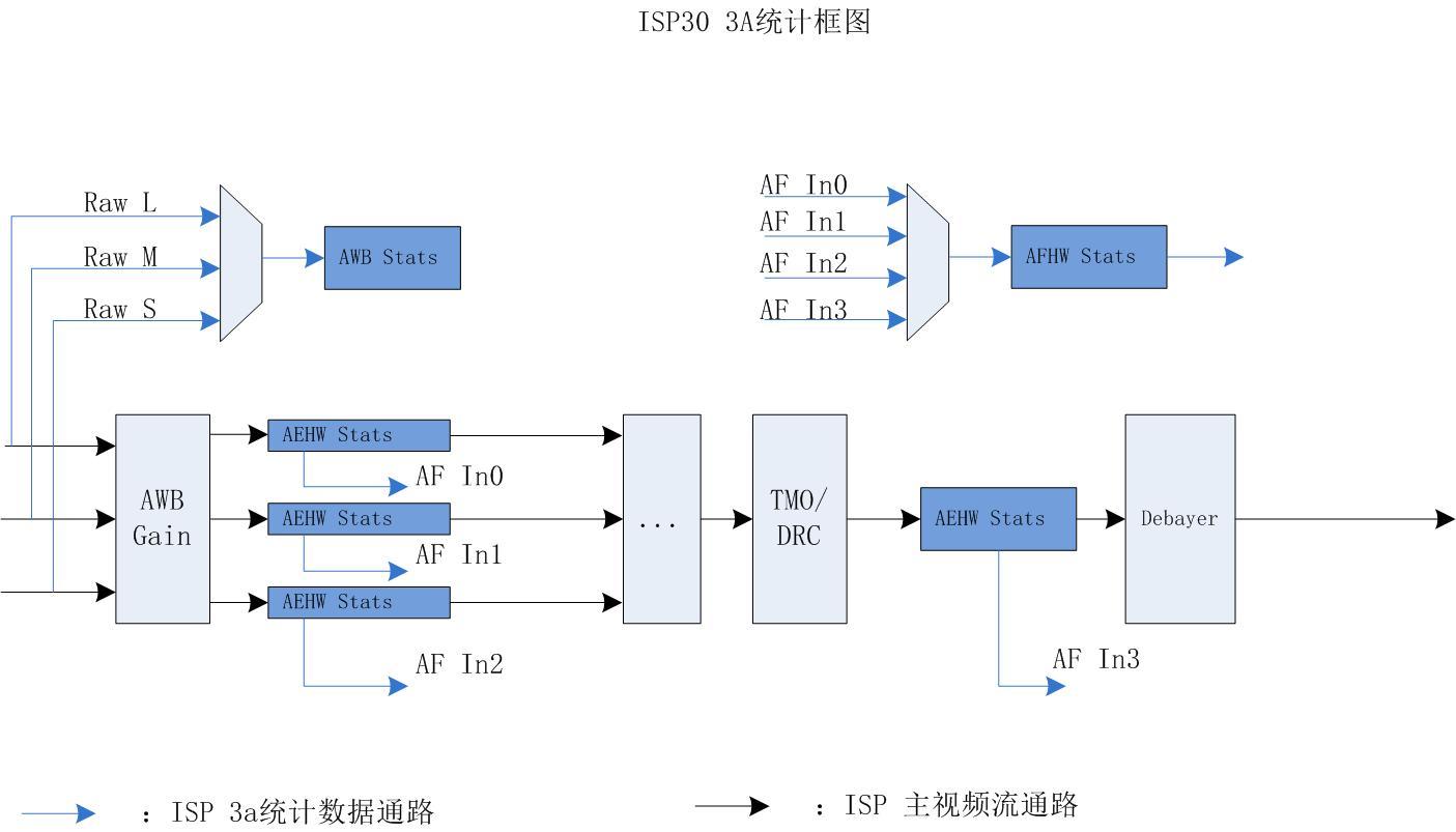
10.2 Description of the feature
10.2.1 AE statistics
AE hardware statistics mainly include the following parts:
256-segment weighted histogram statistics and chunked R/G/B/Y mean statistics based on RAW domain;
10.2.1.1 AE statistics based on raw graphs
The module statistics are divided into block brightness statistics and histogram statistics. According to the supported block size and whether there are independent subwindow statistics, the statistical mode can be divided into big mode and lite mode.
big mode: maximum support 15X15 non-independent sub-window blocking, minimum support 1X1 non- independent sub-window blocking, each block can output 10bit R/B channel luminance average and 12bit G channel average, default to 15X15 blocking; At the same time, 4 independent sub-windows can be set up, each independent sub-window can output the sum of 29-bit R/B channel brightness and 32-bit G channel sum, and the average brightness needs to be divided by the number of pixels of each independent sub- window in the software. In this mode, the weighted histogram statistics are based on the number of tiles and the corresponding assigned weights, and the effective number of pixels in each luminance segment is 28bit.
lite mode: maximum support 5X5 non-independent sub-window blocking, minimum support 1X1 non- independent sub-window blocking, each block can output 10bit R/B channel brightness average and 12bit G channel average, default to 5X5 blocking; Setting up stand-alone child windows is not supported. In this mode, the weighted histogram statistics are based on the number of tiles and the corresponding assigned weights, and the effective number of pixels in each luminance segment is 28bit.
3588 platform, default non-HDR exposure mode, BIG mode (15X15 non-independent sub-window), HDR 2-frame mode, BIG mode (15X15 non-independent sub-window), HDR 3-frame mode, BIG mode for short and long frames (15X15 non-independent sub-window), medium frame in LITE mode (5X5 non- independent sub-window)
10.2.2 AWB statistics
AWB Hardware Statistics Source:
In HDR multi-frame mode, support to select 1 of the 3 channels of L/M/S.
In linear mode, there is only 1 channel of data.
Perform statistics on data after Raw-BLC-LSC
AWB hardware statistics include white point statistics and chunking statistics
White point statistics
Record the cumulative value and number of RGins and BGains in the white areas of 7 light sources and 2 sizes in the main window
Record the cumulative value and number of RGins and BGains in the white areas of 4 light sources and 2 sizes in the sub-window
The RGin and BGain in the 4 UV or XY fields are added to the box, and the number of RGins is added
Chunking statistics Image 15x15 tiles, R, G, B mean of all points or white points for each block
10.2.3 AF statistics
AFHW Stats Hardware Statistics:
In HDR multi-frame mode, support to select 1 of the 3 channels of L/M/S. At the same time, the data after 3-channel synthesis is supported as input.
In linear mode, there is only 1 channel of data.
Support FV output of 2 configurable frequency bands horizontally and FV output of 2 configurable frequency bands in vertical direction
ISP30 AF Hardware Statistics Module Block Diagram
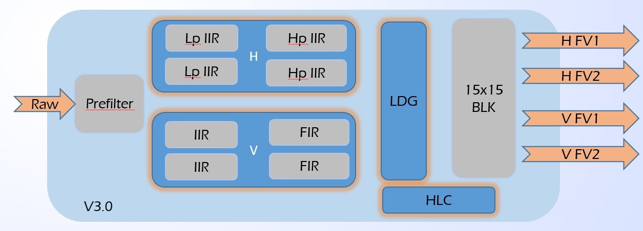
10.3 API reference
10.3.1 rk_aiq_uapi_sysctl_get3AStatsBlk
【Description】
Obtain 3A statistics synchronously.
【Grammar】
XCamReturn
rk_aiq_uapi_sysctl_get3AStatsBlk(const rk_aiq_sys_ctx_t* ctx, rk_aiq_isp_stats_t
**stats, int timeout_ms);
【Parameters】
| Parameter Name | Description | Input/Output |
|---|---|---|
| ctx | AIQ context pointer | Input |
| stats | Statistics structure pointer | Output |
| timeout_ms | Timeout, -1 means infinite wait until there is a statistic | Input |
【Return Value】
| Return value | Description |
|---|---|
| 0 | Success |
| Non-0 | Failure, see Error Code Table |
【Requirements】
Header file: rk_aiq_user_api_sysctl.h
Library file: librkaiq.so
10.3.2 rk_aiq_uapi_sysctl_release3AStatsRef
【Description】
Release the acquired 3A statistical information and use it with the rk_aiq_uapi_sysctl_get3AStatsBlk.
【Grammar】
void
rk_aiq_uapi_sysctl_release3AStatsRef(const rk_aiq_sys_ctx_t* ctx,
rk_aiq_isp_stats_t *stats);
【Parameters】
| Parameter Name | Description | Input/Output |
|---|---|---|
| ctx | AIQ context pointer | Input |
| stats | Statistics structure pointer | Input |
【Return Value】
| Return value | Description |
|---|---|
| 0 | Success |
| Non-0 | Failure, see Error Code Table |
【Requirements】
Header file: rk_aiq_user_api_sysctl.h
Library file: librkaiq.so
Reference code
sdk: external/camera_engine_rkaiq/rkisp_demo/demo/af_algo_demo
10.4 Data type
10.4.1 rk_aiq_isp_stats_t
【Description】 AIQ 3A statistics
【Definition】
typedef struct {
rk_aiq_isp_aec_stats_t aec_stats;
rk_aiq_isp_awb_stats2_v3x_t awb_stats_v3x;
rk_aiq_isp_af_stats_t af_stats;
} rk_aiq_isp_stats_t;
【Member】
| Member Name | Description |
|---|---|
| aec_stats | ae statistics |
| rk_aiq_isp_awb_stats2_v3x_t | awb statistics |
| af_stats | af statistics |
10.4.2 RKAiqAecStats_t
【Description】 Define AE data information, see the function description of AE section for details.
【Definition】
typedef struct RKAiqAecStats_s {
RkAiqAecHwStatsRes_t ae_data;
RKAiqAecExpInfo_t ae_exp;
} RKAiqAecStats_t;
【Member】
| Member Name | Description |
|---|---|
| ae_data | AE Module Hardware Statistics |
| ae_exp | AE module sensor exposure information |
10.4.2.1 RKAiqAecExpInfo_t
【Description】 AE module exposure parameter information
【Definition】
typedef struct RKAiqAecExpInfo_s {
RkAiqExpParamComb_t LinearExp;
RkAiqExpParamComb_t HdrExp[3];
RkAiqIrisParamComb_t Iris;
uint16_t line_length_pixels;
uint32_t frame_length_lines;
float pixel_clock_freq_mhz;
CISFeature_t CISFeature;
RKAiqExpI2cParam_t exp_i2c_params;
} RKAiqAecExpInfo_t;
【Member】
| Member Name | Description |
|---|---|
| LinearExp | Exposure parameter information for non-HDR modes, including exposure actual values and register values in RK format |
| HdrExp | Exposure parameter information for HDR mode, including exposure actual values and register values in RK format, supports up to 3 frame exposures |
| exp_i2c_params | The sensor register value of the exposure parameter, the exposure register value parameter used by third-party AE schemes |
| line_length_pixels | hts, whose value is determined by the sensor’s configuration sequence |
| frame_length_lines | vts, whose value is determined by the configuration sequence of the sensor |
| pixel_clock_freq_mhz | pclk, in MHz, the value of which is determined by the configuration sequence of the sensor |
【Precautions】
HdrExp represents exposure parameter information in HDR mode and supports up to 3TO1. HDR 2TO1: Subscript 0 indicates short frame exposure parameters, subscript 1 indicates long frame exposure parameters, subscript 2 is invalid; HDR 3TO1: Subscript 0 indicates short frame exposure parameters, subscript 1 indicates medium frame exposure parameters, and subscript 2 indicates long frame exposure parameters.
10.4.2.1.1 RkAiqExpParamComb_t
【Description】 AE module exposure parameter information details
【Member】
typedef struct {
RkAiqExpRealParam_t exp_real_params; real value
RkAiqExpSensorParam_t exp_sensor_params;//RK reg value
} RkAiqExpParamComb_t;
| Member Name | Description |
|---|---|
| exp_real_params | The actual physical value of the exposure component |
| exp_sensor_params | The sensor register value of the exposure component, following the RK exposure setting |
typedef struct RkAiqExpRealParam_s {
float integration_time;
float analog_gain;
float digital_gain;
float isp_dgain;
int iso;
int dcg_mode;
} RkAiqExpRealParam_t;
| Member Name | Description |
|---|---|
| integration_time | Exposure integration time in seconds (s) |
| analog_gain | The analog gain/Total gain of the sensor in multiples |
| digital_gain | The digital gain of the sensor, in multiples, is configured to 1x when the digital gain of the sensor compensates for the accuracy of the analog gain, and the overall gain value is written to the analog_gain |
| isp_dgain | ISP digital gain, in multiples, is currently invalid, and the default value is 1x |
| iso | The total gain value, ISO represents the system gain, in constant 50 times multiple, ISO = Total gain * 50 |
| dcg_mode | Dual conversion gain |
typedef struct RkAiqExpSensorParam_s {
unsigned short fine_integration_time;
unsigned short coarse_integration_time;
unsigned short analog_gain_code_global;
unsigned short digital_gain_global;
unsigned short isp_digital_gain;
} RkAiqExpSensorParam_t;
| Member Name | Description |
|---|---|
| fine_integration_time | The fractional line register value of the sensor exposure integration time, which is only required if the sensor supports decimal lines |
| coarse_integration_time | The register value corresponding to the sensor exposure integration time, in the number of rows |
| analog_gain_code_global | Register values corresponding to the analog gain of the sensor |
| digital_gain_global | Register values corresponding to the digital gain of the sensor |
| isp_digital_gain | ISP digital gain register value, temporarily invalid |
【Precautions】
The digital gain of different sensors has different effects, some to increase the sensitivity range, and some to complement the accuracy of the analog gain. Therefore, the digital gain is not listed separately for this time, and its size and corresponding register values are all incorporated into the analog gain.
Dual conversion gain mode has three states, a value of -1 means that the sensor does not support DCG, a value of 0 indicates LCG, and a value of 1 indicates HCG
10.4.2.1.2 RKAiqExpI2cParam_t
【Description】 AE module I2c exposure parameters (generally used by third-party AEs)
【Definition】
#define MAX_I2CDATA_LEN 64
typedef struct RKAiqExpI2cParam_s {
bool bValid;
unsigned int nNumRegs;
unsigned int RegAddr[MAX_I2CDATA_LEN];
unsigned int AddrByteNum[MAX_I2CDATA_LEN];
unsigned int RegValue[MAX_I2CDATA_LEN];
unsigned int ValueByteNum[MAX_I2CDATA_LEN];
unsigned int DelayFrames[MAX_I2CDATA_LEN];
} RKAiqExpI2cParam_t;
【Member】
| Member Name | Description |
|---|---|
| bValid | I2c parameter effective enable bit true: use RKAiqExpI2cParam_t to set register value (generally used by third-party AE); false: Register value setting using register parameters in RK format |
| nNumRegs | The number of register values set |
| AddrByteNum | The bit length of the register address, the maximum number of elements is 64 |
| RegValue | An array of register values with a maximum number of elements of 64 |
| ValueByteNum | The bit length of the register value, the maximum number of elements is 64 |
| DelayFrames | Register value deferred array of frames with a maximum of 64 |
【Precautions】
This register parameter is only valid if the third-party AE application is true and bValid is true, otherwise the RK format register parameter in the RkAiqExpParamComb_t is used by default
The maximum number of register values that can be set is 64
10.4.2.1.3 RkAiqIrisParamComb_t
【Description】 AE module aperture parameters
【Definition】
typedef struct {
RkAiqPIrisParam_t PIris;
RkAiqDCIrisParam_t DCIris;
} RkAiqIrisParamComb_t;
typedef struct {
int step;
int gain;
bool update;
} RkAiqPIrisParam_t;
typedef struct {
int pwmDuty; //percent value,range = 0-100
bool update;
} RkAiqDCIrisParam_t;
【Member】
| Member Name | Child members | Description |
|---|---|---|
| PIris | step gain update |
P aperture parameters: P aperture step register value P aperture step equivalent gain value P aperture step update flag |
| DCIris | pwmDuty update |
DC aperture parameters: PWM duty cycle value, value range: 1~100 DC aperture parameter update flag |
10.4.2.2 RkAiqAecHwStatsRes_t
【Description】 AE module hardware statistics
【Definition】
typedef struct RkAiqAecHwStatsRes_s {
Aec_Stat_Res_t chn[3];
Aec_Stat_Res_t extra;
struct yuvae_stat yuvae;
struct sihist_stat sihist;
} RkAiqAecHwStatsRes_t;
【Member】
| Member Name |
Description |
|---|---|
| chn[3] | The AE module is based on the statistics of the raw graph (after BLC and AWB), compatible with HDR and non-HDR modes, and supports up to HDR 3TO1 S/M/L statistics |
| extra | The AE module is based on the statistics of the raw graph (before Debayer), and in HDR mode, it represents the statistics of the synthesized frame |
| yuvae | The AE module is based on the block information of the RGB diagram before gamma [not supported by the 3588 platform]. |
| sihist | The AE module is based on the histogram information of the pre-gamma RGB diagram [not supported by the 3588 platform] |
【Precautions】
Aec_Stat_Res_t chn[3]: Represents the statistics of the first 3 Raw data paths of the HDR Merge module. For non-HDR mode, the corresponding subscript is 0, and all other subscripts are invalid; HDR 2TO1 mode, when the subscript is 0, it means short frame data path statistics, subscript 1 indicates long frame data path statistics, and subscript 2 is invalid; In HDR 3TO1 mode, the subscript is 0 for short-frame data path statistics, subscript 1 for medium frame data path statistics, and subscript 2 for long-frame data path
statistics. The raw graph-based statistics module has a BLC AWB module before, so the raw-based statistics are affected by the gain value of BLC and AWB. Aec_Stat_Res_t extra: In HDR mode, extra represents the raw graph statistics after HDR compositing. The statistics module has BLC, AWB, HDRMERGE, TMO and other modules before, so the statistical information of this module is affected by the gain of BLC, AWB, HDRMERGE, TMO and other modules. In addition, when the AF module is turned on, this part of the statistics is invalid.
For the 3588 platform, block information and histogram information based on pre-gamma RGB plots are not supported
10.4.2.2.1 Aec_Stat_Res_t
【Description】 The AE module is based on the statistics of the raw graph
【Definition】
typedef struct Aec_Stat_Res_s {
//rawae
struct rawaebig_stat rawae_big;
struct rawaelite_stat rawae_lite;
//rawhist
struct rawhist_stat rawhist_big;
struct rawhist_stat rawhist_lite;
} Aec_Stat_Res_t;
【Member】
| Member Name | Description |
|---|---|
| rawae_big | Big mode chunking statistics based on RAW graphs |
| rawae_lite | Lite mode chunking statistics based on RAW graphs |
| rawhist_big | BIG mode histogram statistics based on RAW graphs |
| rawhist_lite | Lite mode histogram statistics based on RAW graphs |
【Precautions】
For details about the difference between BIG and LITE modes based on RAW graph statistics, please refer to the function description module. It should be noted that the main difference between the big and lite modes is the number of blocks of block statistics of mean brightness and whether independent subwindow mean brightness statistics are supported. BIG and LITE mode histogram statistics based on RAW plots have the same data structure.
3588 platform, default non-HDR exposure mode, configuration BIG mode (15X15 non-standalone subwindow); HDR 2 frame mode, each frame is BIG mode (15X15 non-independent sub-window); HDR 3 frame mode, BIG mode for short and long frames (15X15 non-standalone sub-window), LITE mode for medium frame (5X5 non-standalone sub-window)
10.4.2.2.2 rawaebig_stat
【Description】 The big mode statistics based on the raw graph include the mean R/G/B brightness of 15X15 non-independent sub-windows and the sum of R/G/B brightness of 4 independent sub-windows
【Definition】
struct rawaebig_stat {
unsigned short channelr_xy[RAWAEBIG_WIN_NUM];
unsigned short channelg_xy[RAWAEBIG_WIN_NUM];
unsigned short channelb_xy[RAWAEBIG_WIN_NUM];
unsigned int channely_xy[RAWAEBIG_WIN_NUM]; //not HW!
unsigned long int wndx_sumr[RAWAEBIG_SUBWIN_NUM];
unsigned long int wndx_sumg[RAWAEBIG_SUBWIN_NUM];
unsigned long int wndx_sumb[RAWAEBIG_SUBWIN_NUM];
unsigned short wndx_channelr[RAWAEBIG_SUBWIN_NUM]; //not HW!
unsigned short wndx_channelg[RAWAEBIG_SUBWIN_NUM]; //not HW!
unsigned short wndx_channelb[RAWAEBIG_SUBWIN_NUM]; //not HW!
unsigned char wndx_channely[RAWAEBIG_SUBWIN_NUM]; //not HW!
};
#define RAWAEBIG_WIN_NUM 225
#define RAWAEBIG_SUBWIN_NUM 4
【Member】
| Member Name |
Description |
|---|---|
| channelr_xy | The mean luminance information of the R channel of the BIG mode non-independent subwindow tile. Number of valid bits: 10bit. |
| channelg_xy | G-channel mean luminance information for non-independent subwindow blocks in big mode. Number of valid bits: 12bit. |
| channelb_xy | The average brightness information of the B-channel of the BIG mode non-independent subwindow tile. Number of valid bits: 10bit. |
| wndx_sumr | R channel brightness and information for big mode independent subwindows. Number of valid bits: 29bit. |
| wndx_sumg | G-channel brightness and information for BIG mode independent subwindows. Number of valid bits: 32bit. |
| wndx_sumb | B-channel brightness and information for a separate subwindow in big mode. Number of valid bits: 29bit. |
【Precautions】
Big mode statistics based on raw graph, only contains the statistics of R/G/B 3 channels, if you need Y channel statistics, you can add code in the software to calculate according to the R/G/B statistical values.
BIG mode statistics based on RAW graph, containing 15X15 non-independent subwindows, non- independent subwindows have a minimum size limit, and the minimum size required is 16X4.
BIG mode statistics based on RAW graph, containing 4 independent sub-windows, whose positions can overlap or not, with a maximum size requirement, which must not exceed 2k x 1k.
The channely_xy, wndx_channelr, wndx_channelg, wndx_channelb, and wndx_channely parameters in the structure are all software calculation parameters, which need to be calculated by adding code by software and calculated according to hardware statistical values.
10.4.2.2.3 rawaelite_stat
【Description】 The lite mode statistics based on the raw graph include 5X5 non-independent sub-window block R/G/B mean brightness
【Definition】
struct rawaelite_stat {
unsigned short channelr_xy[RAWAELITE_WIN_NUM];
unsigned short channelg_xy[RAWAELITE_WIN_NUM];
unsigned short channelb_xy[RAWAELITE_WIN_NUM];
unsigned int channely_xy[RAWAELITE_WIN_NUM]; not HW!
};
#define RAWAELITE_WIN_NUM 25
【Member】
| Member Name |
Description |
|---|---|
| channelr_xy | Lite mode non-independent subwindow tile R channel mean luminance information. Number of valid bits: 10bit. |
| channelg_xy | Lite mode non-independent subwindow tile g-channel mean luminance information. Number of valid bits: 12bit. |
| channelb_xy | Lite mode non-independent subwindow tile B-channel mean luminance information. Number of valid bits: 10bit. |
【Precautions】
lite mode statistics based on raw graph, only contains 5X5 non-independent subwindow R/G/B 3 channel statistics, if you need Y channel statistics, you can add code in the software to calculate according to the R/G/B statistical value. Non-standalone subwindows have a minimum size limit, which requires a minimum size of 16X4.
The channely_xy in the structure is a software calculation parameter, which needs to be added to calculate according to the hardware statistical value.
10.4.2.2.4 rawhist_stat
【Description】 Histogram statistics based on RAW plots
【Definition】
struct rawhist_stat {
unsigned int bins[RAWHIST_BIN_N_MAX];
};
#define RAWHIST_BIN_N_MAX 256
【Member】
| Member Name |
Description |
|---|---|
| bins | The histogram is segmented, with a total of 256 segments, and the number of valid bits in each segment: 28bit |
10.4.3 rk_aiq_isp_awb_stats2_v3x_t
【Description】 Define white balance hardware statistics, mainly including white point statistics and chunking statistics
White point statistics
Record the cumulative value and number of RGins and BGain in the white areas of 7 light sources and 2 sizes in the main window;
Record the cumulative value and number of RGin and BGain in the white area of 4 light sources and 2 sizes in the sub-window;
4 UV or XY domain additional boxes in the RGin, BGain cumulative value and number;
white point brightness histogram;
Chunking statistics Image 15x15 blocks (as shown in AWB block schematic) with R, G, B means of all points or white points for each block
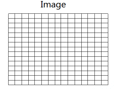
Figure AWB block diagram
【Definition】
typedef struct rk_aiq_isp_awb_stats2_v3x_s {
//method1
rk_aiq_awb_stat_wp_res_light_v201_t light[RK_AIQ_AWB_MAX_WHITEREGIONS_NUM];
int WpNo2[RK_AIQ_AWB_MAX_WHITEREGIONS_NUM];
//method2
rk_aiq_awb_stat_blk_res_v201_t blockResult[RK_AIQ_AWB_GRID_NUM_TOTAL];
//window in pixel domain
rk_aiq_awb_stat_wp_res_light_v201_t
multiwindowLightResult[RK_AIQ_AWB_MAX_WHITEREGIONS_NUM];
//window in xy or uv domain
rk_aiq_awb_stat_wp_res_v201_t
excWpRangeResult[RK_AIQ_AWB_STAT_WP_RANGE_NUM_V201];
//wpno histogram
unsigned int WpNoHist[RK_AIQ_AWB_WP_HIST_BIN_NUM];
} rk_aiq_isp_awb_stats2_v3x_t;
【Member】
| Member Name | Description |
|---|---|
| light | White point statistics results under different light sources in the main window, up to RK_AIQ_AWB_MAX_WHITEREGIONS_NUM light sources; |
| WpNo2 | The number of white points at the intersection of the XY domain and the UV domain under different light sources in the main window, without decimal places. |
| blockResult | The RGB accumulation image of each block is evenly chunked, with a total of 15x15 (RK_AIQ_AWB_GRID_NUM_TOTAL) blocks, as shown in the AWB block diagram |
| multiwindowLightResult | White point statistics under different light sources in several sub-windows (only the first 4 light sources are recorded, all light sources can be recorded by time division multiplexing method), up to 4 sub-windows |
| excWpRangeResult | Statistics of points that fall in the excludeWpRange area (only the first four regions of the excludeWpRange are recorded), up to 4 regions |
| WpNoHist | White dot histogram The number of white dots per bin, no decimal places. Whether the white point of the XY large box or the box in XY is counted is determined by the register xyRangeTypeForWpHist. |
【Precautions】
If the user wants to obtain the global white point statistics results of the main window, the white point statistics results under all light sources can be easily converted.
10.4.4 rk_aiq_awb_stat_wp_res_light_v201_t
【Description】 Defines the white point statistics result under a light source
【Definition】
typedef struct rk_aiq_awb_stat_wp_res_light_v201_s {
rk_aiq_awb_stat_wp_res_v201_t xYType[RK_AIQ_AWB_XY_TYPE_MAX_V201];
} rk_aiq_awb_stat_wp_res_light_v201_t;
【Member】
| Member Name |
Description |
|---|---|
| XYType | The white point statistics of XY boxes of different sizes under a light source, up to RK_AIQ_AWB_XY_TYPE_MAX_V201 boxes, that is, 2 boxes |
10.4.5 rk_aiq_awb_stat_wp_res_v201_t
【Description】 Define the white point statistics result under the XY box of a certain size of a light source, and the non-white point statistical result in the non-white point area
【Definition】
typedef struct rk_aiq_awb_stat_wp_res_v201_s {
long long WpNo;
long long RgainValue;
long long BgainValue;
} rk_aiq_awb_stat_wp_res_v201_t;
【Member】
| Member Name |
Description |
|---|---|
| WpNo | Number of white points, 22-bit integer bits, 10ibit decimal places. where WpNo = ISP hardware statistics white dot / 2^10. |
| RgainValue | Accumulation sum of white point R channels, 22-bit integer bits, 10ibit decimal places |
| BgainValue | Cumulative sum of white point G channel, 22-bit integer bits, 10ibit decimal places |
10.4.6 rk_aiq_awb_stat_blk_res_v201_t
【Description】 Define the statistical results for each block.
If blkMeasureMode = =RK_AIQ_AWB_BLK_STAT_MODE_ALL_V201, the recorded result is the cumulative sum of all points in the block;
If blkMeasureMode = =RK_AIQ_AWB_BLK_STAT_MODE_REALWP_V201, the result of the record is the cumulative sum of all white points in the block;
where blkMeasureMode is the register that controls the statistical content of the block.
【Definition】
typedef struct rk_aiq_awb_stat_blk_res_v201_s {
long long WpNo;
long long Rvalue;
long long Gvalue;
long long Bvalue;
} rk_aiq_awb_stat_blk_res_v201_t;
【Member】
| Member Name | Description |
|---|---|
| WpNo | The number of points within the block |
| Rvalue | The accumulation of all point R channels within the block |
| Gvalue | The accumulation of all point RG channels within the block |
| Bvalue | The accumulation of all point RB channels within the block and |
10.4.7 rk_aiq_af_algo_stat_v30_t
【Description】 Define AF statistics
【Definition】
typedef struct {
unsigned int wndb_luma;
unsigned int wndb_sharpness;
unsigned int winb_highlit_cnt;
unsigned int wnda_luma[RKAIQ_RAWAF_SUMDATA_NUM];
unsigned int wnda_fv_v1[RKAIQ_RAWAF_SUMDATA_NUM];
unsigned int wnda_fv_v2[RKAIQ_RAWAF_SUMDATA_NUM];
unsigned int wnda_fv_h1[RKAIQ_RAWAF_SUMDATA_NUM];
unsigned int wnda_fv_h2[RKAIQ_RAWAF_SUMDATA_NUM];
unsigned int wina_highlit_cnt[RKAIQ_RAWAF_SUMDATA_NUM];
unsigned int int_state;
struct timeval focus_starttim;
struct timeval focus_endtim;
struct timeval zoom_starttim;
struct timeval zoom_endtim;
int64_t sof_tim;
int focusCode;
int zoomCode;
bool focusCorrection;
bool zoomCorrection;
float angleZ;
} rk_aiq_af_algo_stat_v30_t;
【Member】
| Member Name | Description |
|---|---|
| wndb_luma | The brightness value of the standalone window, |
| wndb_sharpness | The clarity value of the stand-alone window |
| winb_highlit_cnt | The highlight count value of the standalone window |
| wnda_luma | The brightness value of the 15*15 subwindow under the main window |
| wnda_fv_v1 | V1 clarity value of 15*15 subwindow under the main window |
| wnda_fv_v2 | V2 sharpness value of 15*15 subwindow under the main window |
| wnda_fv_h1 | H1 clarity value of 15*15 subwindow under the main window |
| wnda_fv_h2 | H2 clarity value of 15*15 subwindow under the main window |
| wina_highlit_cnt | The highlight count value of the 15*15 subwindow under the main window |
| int_state | The RK AF algorithm is used, which can be ignored |
| focus_starttim | The RK AF algorithm is used, which can be ignored |
| focus_endtim | The RK AF algorithm is used, which can be ignored |
| zoom_starttim | The RK AF algorithm is used, which can be ignored |
| zoom_endtim | The RK AF algorithm is used, which can be ignored |
| sof_tim | The frame start time of this data frame in ns |
| focusCode | The RK AF algorithm is used, which can be ignored |
| zoomCode | The RK AF algorithm is used, which can be ignored |
| focusCorrection | The RK AF algorithm is used, which can be ignored |
| zoomCorrection | The RK AF algorithm is used, which can be ignored |
| angleZ | The RK AF algorithm is used, which can be ignored |
11. Debug & FAQ
11.1 How to get the version number
AIQ provides version release date, AIQ version, IQ parser version, and version information of each algorithm module of ISP.
11.1.0.1 Get abbreviated version information
strings librkaiq.so | grep -w AIQ
AIQ: v0.1.6
11.1.0.2 Get full version information
1. The aiq library in the SDK is compiled to the Release version by default, and you need to change it to the Debug version, recompile the aiq library, and update it to the device.
SDK/external/camera_engine_rkaiq/CMakeLists.txt:
if(NOT CMAKE_BUILD_TYPE STREQUAL "Release")
add_definitions(-DBUILD_TYPE_DEBUG)
endif()
Changed to:
#if(NOT CMAKE_BUILD_TYPE STREQUAL "Release")
add_definitions(-DBUILD_TYPE_DEBUG)
#endif()
2. Under the default print level, the AIQ library loaded and running will not print, you can set the log level of the xcore module to print the AIQ version information:
export persist_camera_engine_log=0x1000000ff2
3. The printed version information when AIQ is started is as follows:
************************** VERSION INFOS **************************
version release date: 2020-06-05
AIQ: v0.1.6
IQ PARSER: v1.0.0
RK INTEGRATED ALGO MODULES:
AWB: v0.0.9
AEC: v0.1.1
AF: v0.0.9
AHDR: v0.0.9
ANR: v0.0.9
ASHARP: v0.0.9
ADEHAZE: v0.0.9
AGAMMA: v0.0.9
A3DLUT: v0.0.9
ABLC: v0.0.9
ACCM: v0.0.9
ACGC: v0.0.9
ACP: v0.0.9
ADEBAYER: v0.0.1
ADPCC: v0.0.9
AGIC: v0.0.9
AIE: v0.0.1
ALDCH: v0.0.9
ALSC: v0.0.9
AORB: v0.0.9
AR2Y: v0.0.9
ASD: v0.0.9
AWDR: v0.0.9
************************ VERSION INFOS END ************************
11.1.1 Version number matching rule description
The matching rules between AIQ and IQ Tool and ISP Driver are as follows:
v A . B. C
where B is the base-16 representation, bit[0:3] identifies the matching version of AIQ and IQ Tool, and bit[4:7] identifies the matching version of AIQ and ISP driver, for example:
ISP driver:v 1. 0x3.0 matches AIQ:v1.0x30.0 and AIQ:v1.0x40.0.
IQ tool:v 1. 0x3.0 matches AIQ:v1.0x33.0 and AIQ:v1.0x30.0, where AIQ version number C is not 0, there may be a version mismatch, for IQ Tool matching, it is recommended to use the AIQ version with C version number 0 first.
11.2 AIQ Log
11.2.1 Overview
AIQ uses 64bits to represent the log level of all modules, and the bitmaps and descriptions of each module are as follows:
bit: [63-39] 38 37 36 35 34 33 32 31
mean: [U] [CAMHW][ANALYZER][XCORE][ASD][ACGC][AFEC][AORB][ASHARP]
bit: 30 29 28 27 26 25 24 23 22
mean:[AIE][ACP][ACSM][ALDCH][A3DLUT][ADEHAZE][AWDR][AGAMMA][ACCM]
bit: 21 20 19 18 17 16 15 14 13 12
mean:[ADEBAYER][AGIC][ALSC][ANR][AHDR][ADPCC][ABLC][AF][AWB][AEC]
bit: 11-4 3-0
mean:[sub modules][level]
[U] means unused now.
[level] : use 4 bits to define log levels.
each module log has following ascending levels:
0: error
1: warning
2: info
3: debug
4: verbose
5: low1
6-7: unused, now the same as debug
[sub modules] : use bits 4-11 to define the sub modules of each module,
thespecific meaning of each bit is decided by the module itself. These bitsis
designed to implement the sub module's log switch.
[modules] : AEC, AWB, AF ...
set debug level example:
eg. set module af log level to debug, and enable all sub modules of af:
Android:
setprop persist.vendor.rkisp.log 0x4ff4
Linux:
export persist_camera_engine_log=0x4ff4
And if only want enable the sub module 1 log of af:
Android:
setprop persist.vendor.rkisp.log 0x4014
Linux:
export persist_camera_engine_log=0x4014
As explained above, the switch level of each module is controlled by setting the environment variable persist_camera_engine_log the Linux environment.
| Module | Debug log | Verbose log |
|---|---|---|
| AE | export persist_camera_engine_log=0x1ff3 | export persist_camera_engine_log=0x1ff4 |
| AWB | export persist_camera_engine_log=0x2ff3 | export persist_camera_engine_log=0x2ff4 |
| AF | export persist_camera_engine_log=0x4ff3 | export persist_camera_engine_log=0x4ff4 |
| HDR | export persist_camera_engine_log=0x20ff3 | export persist_camera_engine_log=0x20ff3 |
| NR | export persist_camera_engine_log=0x40ff3 | export persist_camera_engine_log=0x40ff4 |
| Dehaze | export persist_camera_engine_log=0x2000ff3 | export persist_camera_engine_log=0x2000ff3 |
| Sharp | export persist_camera_engine_log=0x80000ff3 | export persist_camera_engine_log=0x80000ff4 |
| CAMHW | export persist_camera_engine_log=0x4000000ff3 |
export persist_camera_engine_log=0x4000000ff4 |
To view the current log level, run the following command:
[root@RV1126_RV1109:/]# echo $persist_camera_engine_log
0x4014
11.2.2 AE
11.2.2.1 Configuration guide
| Log level |
Description and enabling suggestions |
|---|---|
| Error | Enabled by default Critical error |
| Warning | Not enabled by default Warn error, the algorithm may have exception handling for the error, and the algorithm can continue to run |
| Info | Not enabled by default Basic debugging information: Frame-by-frame output information: None Event information: The running status information and frame rate information in the algorithm are generally only printed when initializing, switching resolution, and modifying configuration parameters Suggestion: It is used to know the running status and frame rate value of the algorithm |
| Log level |
Description and enabling suggestions |
|---|---|
| Debug | Not enabled by default Basic debugging information (increased relative to Info level): Frame-by-frame output information: frame number, frame-matched exposure, frame-matched AE statistics (image brightness), and exposure result value Event information: Suggestion: Debug problems such as image brightness flickering with continuous image brightness, exposure, and other information |
| Verbose | Not enabled by default Basic debugging information (relative to Debug level increase): Frame-by-frame output information: algorithm related operation result information Event information: Suggestion: Generally, it is not enabled, and it is enabled when the debug level cannot judge the problem |
| Sub modules bit |
Description and enabling recommendations |
|---|---|
| bit[4] | Log level related to AE parameter configuration Suggestion: When reading IQ or API setting parameters, you can check whether the configuration parameters are correct according to the log. |
| bit[5] | The AE information processing module logs the switch, which calculates the environment and image-related indicators according to AE statistics. Suggestion: Read luminance information related to statistical values. |
| bit[6] | AE exposure calculation module log switch. Suggestion: Read information related to exposure results |
| bit[7] | log level associated with the Airis aperture algorithm, Suggestion: Issues with variable aperture. |
| bit[8:11] | void |
11.2.2.2 Log interpretation
Due to space limitations, only the debug level (0x1ff3, corresponding to the debug level information of all submodules of AE) is interpreted here.
Linear mode AE LOG

Figure 3-1 LINEAR MODE AE LOG
Figure 3-1 shows an example of AE LOG in linear mode. Line1:
Cur-Exp: FrmId=270,gain=0x36a,time=0x576,envChange=0,dcg=-1,pirs=0
Exposure parameter information for the current frame.
| Member name |
Description |
|---|---|
| FrmId | The frame number of the current frame |
| gain | The sensor exposure gain register value for the current frame |
| time | The sensor exposure time register value for the current frame |
| envChange | Whether the ambient brightness has changed abruptly in the current frame. 0: No sudden change in ambient brightness; 1: Ambient brightness mutation |
| dcg | DCG mode corresponding to the current frame. -1: The sensor does not support DCG mode or switches DCG mode inside the sensor; 0: LCG mode; 1: HCG mode |
| pirs | The p-iris aperture stepper motor position corresponding to the current frame. If the Airis function is disabled, this parameter is invalid and meaningless. |
Line2:
Last-Res:FrmId=269,gain=0x356,time=0x576,pirs=0
The new exposure parameters set by the last run AE are some of the same as those in (1), and will not be repeated here. By comparing the exposure parameter LOG information of Line1 and Line2, we can know whether the current exposure is consistent with the new exposure, that is, whether the new exposure has taken effect. Line3:
================================= Linear-AE (enter)===============================
Enter the AE control algorithm module, Linear-AE indicates that the current linear exposure mode is present.
Line4:
Framenum=270
Cur gain=6.826667,time=0.029987,pirisGain=0,RawMeanluma=29.564444,YuvMeanluma=34.875557,Is Converged=0
| Member name |
Description |
|---|---|
| Framenum | The frame number of the current frame |
| gain | The sensor exposure gain value corresponding to the current frame |
| time | The sensor exposure time value corresponding to the current frame |
| pirisGain | The equivalent gain value of the p-iris aperture corresponding to the current frame. If the Airis function is turned off, this parameter is invalid and meaningless. |
| RawMeanluma | The brightness of the Debayer front RAW image corresponding to the current frame has been subtracted from the black level and multiplied by AWB Gain. |
| YuvMeanluma | The brightness of the RGB figure before gamma corresponding to the current frame is used to judge the influence of the module after debayer on the brightness. |
| IsConverged | Whether the exposure of the current frame has converged. 0: exposure does not converge; 1: The exposure has converged |
Line 5:
AecClmExecute: NewExposure(0.180993) SplitGain(6.033096) SplitIntegrationTime(0.030000) SplitPirisGain(0)
| Member name | Description |
|---|---|
| NewExposure | The new exposure value derived by the AE control algorithm |
| SplitGain | New sensor exposure gain |
| SplitIntegrationTime | New sensor exposure time |
| SplitPirisGain | New P-IRIS aperture equivalent gain value. If the Airis function is turned off, this parameter is invalid and meaningless. |
Line6:
calc result:SetPoint=22.000000,gain=6.023529,time=0.029987,piris=0,reggain=854,regtime=1398
The new exposure that is finally set
| Member name |
Description |
|---|---|
| SetPoint | Target brightness value |
| gain | The final new exposure gain value |
| time | The final new exposure time value |
| piris | The final new P-IRIS aperture equivalent gain value. If the Airis function is turned off, this parameter is invalid and meaningless. |
| reggain | The register value corresponding to the final new exposure gain value |
| regtime | The register value corresponding to the final new exposure time value |
In summary, you can know the brightness of the current frame RawMeanLuma, and the corresponding target brightness setpoint. The new exposure is calculated by comparing the brightness of the picture with the target brightness. HDR Mode AE LOG:

Figure 3-2 HDR mode AE LOG
Line1:
Cur-Exp: FrmId=22,S-gain=0x0,S-time=0x2b6,M-gain=0xb,M-time=0x1a5e,L-gain=0x0,L- time=0x0,envChange=1,dcg=-1--1--1,Piris=0
Exposure parameter information for the current frame.
| Member name |
Description |
|---|---|
| FrmId | The frame number of the current frame |
| S/M/L-gain | The sensor exposure gain register value corresponding to each frame of the current HDR. S/M is valid in HDR 2 frame mode; In HDR 3 frame mode, both S/M/L are valid |
| S/M/L-time | The sensor exposure time register value for each frame of the current HDR. S/M is valid in HDR 2 frame mode; In HDR 3 frame mode, both S/M/L are valid |
| envChange | Whether the ambient brightness has changed abruptly in the current frame. 0: No sudden change in ambient brightness; 1: Ambient brightness mutation |
| dcg | The DCG mode corresponding to the current frame corresponds to 3 short, medium and long frames. In HDR 2 frame mode, the first two values are valid, representing the DCG mode of short and long frames, respectively; In HDR 3 frame mode, the three values represent the short, medium, and long DCG mode. -1: The sensor does not support DCG mode or switches DCG mode inside the sensor; 0: LCG mode; 1: HCG mode |
| pirs | The p-iris aperture stepper motor position corresponding to the current frame. If the Airis function is disabled, this parameter is invalid and meaningless. |
Line2:
Last-Res:FrmId=20,S-gain=0x5,S-time=0x8ca,M-gain=0x11,M-time=0x1a5e,L-gain=0x0,L- time=0x0
The new exposure parameters set by the last run AE are some of the same as those in (1), and will not be repeated here. By comparing the exposure parameter LOG information of Line1 and Line2, we can know whether the current exposure is consistent with the new exposure, that is, whether the new exposure has taken effect.
Line3:
================================= HDR-AE (enter)===============================
Enter the AE control algorithm module, HDR-AE indicates that the current HDR exposure mode is present.
Line4:
AecRun: SMeanLuma=9.342692, MMeanLuma=37.698597,LMeanLuma=0.000000,TmoMeanluma=37.571430,Isconverged=0,Longfr m=0
| Member name | Description |
|---|---|
| S/M/LMeanLuma | The average luminance of each frame of the current HDR. S/M is valid in HDR 2 frame mode; In HDR 3 frame mode, both S/M/L are valid. |
| TmoMeanluma | The average luminance output of the TMO module in the current frame. |
| Isconverged | Whether the exposure of each frame of the current HDR converges. 0: exposure does not converge; 1: Exposure has converged. |
| Longfrm | The long frame mode state of the current frame. 0: Long frame mode is off; 1: Long frame mode is on. |
Line5:
Framenum=22 Cur Piris=0, Sgain=1.000000,Stime=0.002570,mgain=1.462177,mtime=0.025000,lgain=1.000000,ltime=0.000000
| Member name |
Description |
|---|---|
| Framenum | The frame number of the current frame. |
| s/m/lgain | The sensor exposure gain value corresponding to the current frame. In HDR 2 frame mode, s/m is valid; In HDR 3 frame mode, both s/m/l are valid. |
| s/m/ltime | The sensor exposure time value corresponding to the current frame. In HDR 2 frame mode, s/m is valid; In HDR 3 frame mode, both s/m/l are valid. |
| piris | The equivalent gain value of the p-iris aperture corresponding to the current frame. If the Airis function is disabled, this parameter is invalid and meaningless. |
Line6:
S-HighLightLuma=197.250000,S-Target=100.000000,S-GlobalLuma=9.342692,S-Target=19.959433
Short frame control algorithm LOG
| Member name | Description |
|---|---|
| S-HighLightLuma | The brightness of the highlighted area of the current short frame. |
| S-Target | The target brightness of the highlighted area of the current short frame. |
| S-GlobalLuma | Average brightness of the current short frame global area. |
| S-Target | The target brightness of the current short frame global area. |
Line7:
L-LowLightLuma=29.626642,L-Target=48.572094,L-GlobalLuma=37.698597,L-Target=77.620155
Long frame control algorithm LOG
| Member name | Description |
|---|---|
| L-LowLightLuma | Current long frame dark area brightness |
| L-Target | Target brightness for the current long frame dark area. |
| L-GlobalLuma | Average brightness of the global area of the current long frame. |
| L-Target | The target brightness of the current long frame global area. |
Line8:
calc result:piris=0,sgain=1.000000,stime=0.005081,mgain=1.862087,mtime=0.025000,lgain=0.000000,lti me=0.000000
AE controls the exposure result output by the algorithm
| Member name |
Description |
|---|---|
| s/m/lgain | The final new sensor exposure gain value. In HDR 2 frame mode, s/m is valid; In HDR 3 frame mode, both s/m/l are valid |
| s/m/ltime | The final new sensor exposure time value. In HDR 2 frame mode, s/m is valid; In HDR 3 frame mode, both s/m/l are valid |
| piris | The final new P-IRIS aperture is equivalent to the gain value. If the Airis function is disabled, this parameter is invalid and meaningless. |
11.2.3 AWB
11.2.3.1 Configuration guide
| Log level |
Description and enabling recommendations |
|---|---|
| Error | Enabled by default Critical error |
| Warning | Enabled by default Warn error, for which there may be exception handling internally. |
| Info | Not enabled by default Basic debugging information: Frame-by-frame output information: wbgain results Event Information: Suggestion: |
| Log level |
Description and enabling recommendations |
|---|---|
| debug | Not enabled by default Basic debug information (relative to Info level increase): Frame by frame output information: white balance convergence state, ambient brightness, number of white points, total color temperature information, probability of the first four light sources with high probability, etc Event information: The relevant attribute information is printed after the AWS API is called Recommendation:When there is a limit on the output log size, this level can be used to obtain key log information for debugging |
| Verbose | Not enabled by default Basic debugging information (relative to Debug level increase): Frame-by-frame output information: white point statistics (white balance gain, number of white points) of each light source, and strategy-related intermediate results, etc Event Information: Suggestion:It is recommended to use this level to catch the complete log for debugs |
| Sub modules bit | Description and enabling recommendations |
|---|---|
| bit[4:11] | void |
11.2.3.2 Log interpretation
Refer to《Rockchip_Color_Optimization_Guide_ISP2x_CN》
11.2.4 AF
11.2.4.1 Configuration guide
| Log level |
Description and enabling recommendations |
|---|---|
| Error | Enabled by default Critical error |
| Warning | Not enabled by default Warn error, for which there may be exception handling internally. |
| Info | Not enabled by default Basic debugging information: Frame-by-frame output information: The final result of the focus search algorithm Event Information: suggestion: |
| Log level |
Description and enabling recommendations |
|---|---|
| debug | Not enabled by default Basic debugging information (increased relative to Info level): Frame-by-frame output information: FV statistical value, motor movement position information Event information: Focus trigger, clear position search, zoom, focus following, focus Suggestion: It is recommended to use this level to catch the complete log for debugs |
| Verbose | Not enabled by default Basic debugging information (relative to Debug level increase) : None Frame-by-frame output information: Event Information: Recommendation:None |
| Sub modules bit | Description and enabling recommendations |
|---|---|
| bit[4:11] | void |
11.2.4.2 Log interpretation
11.2.5 MERGE
11.2.5.1 Configuration guide
| Log level |
Description and enabling recommendations |
|---|---|
| Info | Not enabled by default Basic debugging information: Frame-by-frame output information: Not yet used Event Information: Not yet used suggestion:Shut down |
| debug | Not enabled by default Basic debugging information: Frame-by-frame output information: Merge debugging information Event Information: Not yet used suggestion:Turn on when the brightness of the screen does not meet expectations, or the contrast ratio is not enough after TMO |
| Verbose | Not enabled by default Basic debug information (increased relative to Verbose rating): Frame-by-frame output information: Mrerge exposure related information Event Information: Not yet used Suggestion:When the screen flashes, confirm from the AE log that TMO is turned on when flashing for RK personnel to use debugs |
| Sub modules bit | Description and enabling recommendations |
|---|---|
| bit[4:11] | void |
11.2.5.2 Log interpretation
When the mode is linear, the merge log level is as follows:
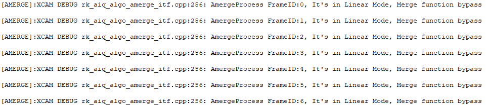
When the mode is HDR and the base frame is long, the merge log level is 10000000ff3

| Name | Description |
|---|---|
| FrameID | Frame number |
| HDRFrameNum | Number of HDR frames |
| LongFrmMode | Long frame mode switch, 0: off, 1: on |
| MergeApiMode | API pattern |
| EnvLv | Ambient brightness |
| MoveCoef | Motion variables |
| bypass | The current frame bypass switch, 0: off, 1: on |
| BaseFrm | Base frame mode, 0: long frame mode, 1: short frame mode |
| OECurve_smooth | The slope of the current frame overexposure curve, the value range [0,200], is obtained by the inverse normalization of the parameters in JSON, with a coefficient of 200. |
| OECurve_offset | The offset value of the current frame overexposure curve, in the range [108,280]. |
| MDCurveMS_smooth | The slope of the motion curve between the frame and the short frame in the current frame, the value range is [0,200], which is obtained by the inverse normalization of the parameters in JSON with a coefficient of 200. |
| MDCurveMS_offset | The offset value of the motion curve between the frame and the short frame in the current frame is in the range of [0.26,100], which is obtained by the inverse normalization of the parameters in JSON with a coefficient of 100. |
| MDCurveLM_smooth | The slope of the motion curve between the current frame length frame and the middle frame, the value range is [0,200], which is obtained by the inverse normalization of the parameters in JSON, with a coefficient of 200. |
| MDCurveLM_offset | The motion curve offset value between the current frame length frame and the middle frame is in the range of [0.26,100], which is obtained by the inverse normalization of parameters in JSON with a coefficient of 100. |
When the mode is HDR and the base frame is short, the merge log level is 10000000ff3

| Name | Description |
|---|---|
| FrameID | Frame number |
| HDRFrameNum | Number of HDR frames |
| LongFrmMode | Long frame mode switch, 0: off, 1: on |
| MergeApiMode | API pattern |
| EnvLv | Ambient brightness |
| MoveCoef | Motion variables |
| bypass | The current frame bypass switch, 0: off, 1: on |
| BaseFrm | Base frame mode, 0: long frame mode, 1: short frame mode |
| OECurve_smooth | The slope of the current frame overexposure curve, the value range [0,200], is obtained by the inverse normalization of the parameters in JSON, with a coefficient of 200. |
| OECurve_offset | The offset value of the current frame overexposure curve, in the range [108,280]. |
| MDCurve_Coef | The current frame control coefficient, the value range [0,1], the default value is 0.05, and the accuracy is 0.0001. |
| MDCurve_ms_thd0 | The control coefficient of short frames in the current frame is in the range of [0,1], and the default value is 0.0 and the accuracy is 0.1. |
| MDCurve_lm_thd0 | The frame control coefficient in the current frame length is in the range [0,1], and the default value is 0.0 and the accuracy is 0.1. |
11.2.6 DRC
11.2.6.1 Configuration guide
| Log level |
Description and enabling recommendations |
|---|---|
| Info | Not enabled by default Basic debugging information: Frame-by-frame output information: Not yet used Event Information: Not yet used suggestion:Shut down |
| debug | Not enabled by default Basic debugging information: Frame-by-frame output information: DRC debug information Event Information: Not yet used Recommendation: Turn on when the brightness of the picture does not meet expectations, or the contrast ratio is not enough after TMO |
| Log level |
Description and enabling recommendations |
|---|---|
| Verbose | Not enabled by default Basic debug information (increased relative to Verbose rating): Frame-by-frame output information: DRC exposure-related information Event Information: Not yet used Suggestion: When the screen flashes, confirm from the AE log that TMO is turned on when flashing for RK personnel to use debugs |
| Sub modules bit | Description and enabling recommendations |
|---|---|
| bit[4:11] | void |
11.2.6.2 log interpretation
When the DRC log level is 20ff3

| Name | Description |
|---|---|
| FrameID | Frame number |
| HDRFrameNum | Number of HDR frames |
| LongFrmMode | Long frame mode switch, 0: off, 1: on |
| DRCApiMode | API pattern |
| EnvLv | Ambient brightness |
| bypass | The current frame bypass switch, 0: off, 1: on |
| Enable | DRC switch |
| DrcGain | The current frame DRC block gain, value range [1,8]. |
| Alpha | The current frame DrcGain Alpha value, the value range [0,1]. |
| Clip | The current frame DrcGain Clip value, value range [0,64]. |
| Strength | HiLight highlight area detail of the current frame, value range [0,1]. |
| CompressMode | The current frame CompressSetting mode. |
| LocalWeit | Local weight of the current frame, value range [0, 1], 0:Global, 1: All Local, default value 0. |
| LocalAutoEnable | The current frame is automatically LocalWeit switch, the value range is [0,1], the default value is 1, and the accuracy is 1. |
| LocalAutoWeit | The current frame automatically has a LocalWeit value, the value range is [0,1], the default value is 0.4, and the accuracy is 0.01. |
| GlobalContrast | The global contrast ratio of the current frame, the value range [0,1], the default value is 0, and the accuracy is 0.01. |
| LoLitContrast | The contrast ratio of the current frame in the low volume area, the value range is [0,1], the default value is 0, and the accuracy is 0.01. |
11.2.7 NR&Sharp
11.2.7.1 Configuration guide
| Log level |
Description and enabling recommendations |
|---|---|
| error | Enabled by default Basic debugging information: Frame by frame output information: Critical errors in prints that may cause the software to crash Event Information: Not yet used Recommended:Turn on |
| Log level |
Description and enabling recommendations |
|---|---|
| Info | Not enabled by default Basic debugging information: Frame-by-frame output information: all function call information, no register values printed. More information overall. Event Information: Not yet used Recommendation: It is not recommended to turn on this item when the effect is not abnormal and there is no error. It is generally recommended to use the io command to print register values. |
| debug | Not enabled by default Basic debugging information (relative to Info level increase): Frame-by-frame output information: All function call information, including register value printing, register value printing information is more. Event Information: Not yet used Recommendation: When there is a serious error in the effect, it is recommended to turn this on and provide it to rk debug use. |
| Sub modules bit | Description and enabling recommendations |
|---|---|
| bit[4:11] | void |
11.2.7.2 log interpretation
11.2.8 Dhz&Ehz
11.2.8.1 Configuration Guide
| Log level | Description and enabling recommendations |
|---|---|
| Info | Not enabled by default Basic debugging information: Frame-by-frame output information: Not yet used Event Information: Not yet used suggestion: |
| debug | Not enabled by default Basic debugging information (relative to Info level increase): Frame-by-frame output information: DHZ & Ehz debug information Event Information: suggestion: |
| Log level | Description and enabling recommendations |
|---|---|
| Verbose | Not enabled by default Basic debug information (increased relative to Verbose rating): Frame-by-frame output information: Not yet used Event Information: Not yet used Suggestion: |
| Sub modules bit | Description and enabling recommendations |
|---|---|
| bit[4:11] | void |
11.2.8.2 Log interpretation
When the Enhance feature is enabled, the Dehaze log level is 2000ff3
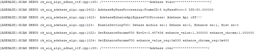
| Name | Description |
|---|---|
| FrameID | Frame number |
| byPassProc | The current frame bypass switch, 0: off, 1: on |
| ISO | ISO |
| Dehaze module en | Dehaze module switch |
| Dehaze en | Dehaze function switch |
| Enhance en | Enhanced function switch |
| Hist en | Hist function switch |
| EnvLv | The ambient brightness of the current frame |
| enhance_value | The current frame has a general contrast force, the value range [0,16], and the recommended range [1, 2]. |
| enhance_chroma | Enhanced adjustment parameters for the chromaticity of the current frame, value range [0,16], recommended range [1, 2]. |
| enhance_value_reg | The current frame has a generic contrast force reg value. |
| enhance_chroma_reg | The REG value of the enhanced tuning parameter for the current frame chromaticity. |
When the Dehaze function is enabled and cfg_alpha=0, the Dehaze log level is 2000ff3

| Name | Description |
|---|---|
| FrameID | Frame number |
| byPassProc | The current frame bypass switch, 0: off, 1: on |
| ISO | ISO |
| Dehaze module en |
Dehaze module switch |
| Dehaze en | Dehaze function switch |
| Enhance en | Enhanced function switch |
| Hist en | Hist function switch |
| cfg_alpha | The proportion of software configuration, the value range [0,1], the default value is 1, and the accuracy is 0.01. |
| EnvLv | The ambient brightness of the current frame |
| air_max | The maximum limit of the current frame AIR adaptation, the value range [230, 250], the default value is 250. |
| air_min | The minimum value limit of the current frame AIR adaptation, the value range [230, 250], the default value is 200. |
| tmax_base | The current frame tmax adaptive base value, default 125, the corresponding configuration is as follows, 200 (131), 210 (125), 220 (119), 230 (114), 240 (109), 250 (105), recommended 131-105 |
| wt_max | The maximum value limit of the current frame wt adaptation, the value range [0.75, 0.9], the default value is 0.9. |
When the Dehaze function is enabled and cfg_alpha=1, the Dehaze log level is 2000ff3

| Name | Description |
|---|---|
| FrameID | Frame number |
| byPassProc | The current frame bypass switch, 0: off, 1: on |
| ISO | ISO |
| Dehaze module en |
Dehaze module switch |
| Dehaze en | Dehaze function switch |
| Enhance en | Enhanced function switch |
| Hist en | Hist function switch |
| cfg_alpha | The proportion of software configuration, the value range [0,1], the default value is 1, and the accuracy is 0.01. |
| EnvLv | The ambient brightness of the current frame |
| cfg_air | The current frame software configures air, atmospheric light coefficient, value range [0, 255], default value 210. |
| cfg_tmax | The current frame software configures tmax, the maximum value of dehazing, the value range [0, 1], and the default value is 0.2. |
| cfg_wt | The current frame software configures wt, image dehazing force, value range [0, 1], default value 0.8. |
When the Hist function is enabled, the Dehaze log level is 2000ff3

| Name | Description |
|---|---|
| FrameID | Frame number |
| byPassProc | The current frame bypass switch, 0: off, 1: on |
| ISO | ISO |
| Dehaze module en |
Dehaze module switch |
| Dehaze en | Dehaze function switch |
| Enhance en | Enhanced function switch |
| Hist en | Hist function switch |
| cfg_alpha | The proportion of software configuration, the value range [0,1], the default value is 1, and the accuracy is 0.01. |
| EnvLv | The ambient brightness of the current frame |
| hist_para_en | The current frame histogram stretch control switch. |
| hist_gratio | The current frame histogram stretch multiplier, histogram equalization control coefficient, value range [0, 32]. |
| hist_th_off | The histogram statistical threshold of the current frame, the value range [0, 255], the default value is 64. |
| hist_k | The current frame histogram adaptive threshold magnification, value range [0, 7), default value 2. |
| hist_min | The minimum value of the histogram statistical threshold of the current frame, the value range [0,2], and the default value is 0.016. |
| hist_scale | The current frame histogram equalization control coefficient, the value range [0, 32]. |
| cfg_gratio | The current frame software configures the histogram stretch multiplier and the histogram equalization control coefficient, and the value range [0, 32]. |
11.2.9 CamHW
11.2.9.1 Configuration guide
| Log level | Description and enabling recommendations |
|---|---|
| Error | Enabled by default Critical error |
| Warning | Not enabled by default Warning error, the algorithm may have exception handling for the error. |
| Log level | Description and enabling recommendations |
|---|---|
| Info | Not enabled by default Basic debugging information: Frame-by-frame output information: Event Information: Suggestion: |
| Debug | Not enabled by default Basic debugging information (increased relative to Info level): Frame-by-frame output information: Event Information: Suggestion: |
| Verbose | Not enabled by default Basic debugging information (increased relative to Debug level): Frame-by-frame output information: Event Information: Suggestion:存在单次大量信息输出,谨慎使用 |
| Low1 | Not enabled by default Basic debugging information (increased relative to Debug level): Frame-by-frame output information: Event information: Function call path information Suggestion: |
| Sub modules bit |
Description and enabling recommendations |
|---|---|
| bit[4] | 30 submodule log switch. Responsible for the HWI process control part. suggestion: It is recommended to enable the following submodules together. |
| bit[5] | Isp30Params and Isp30PollThread submodule log switches. Responsible for the processing of ISP parameters, data streams, events, etc. suggestion: Suspected parameters do not match the video frame, timing settings are abnormal, and other issues In readback offline mode, data flow disconnection and other issues |
| bit[6] | The SensorHw submodule log switch. Responsible for the camera sensor related parts. suggestion: Suspected CIS exposure settings and other issues |
| bit[7] | FlashLight submodule log switch. Responsible for the fill light control part. suggestion: Fill light control issues. |
| bit[8] | The LensHw submodule log switch. Responsible for the lens motor control part. suggestion: Motor control and other issues |
| bit[9] | 30SpThread submodule switch. Internal modules are reserved for use. |
| bit[10:11] | void |
11.2.9.2 log interpretation
CamHwIsp20 Submodule

The above log is only printed once when the AIQ library is loaded, from which the link relationship between the camera sensor, ISP and ISPP can be obtained, and the information is obtained from the analysis of the media node topology, from which you can know whether the camera sensor is detected normally.

The log above figure shows the new parameters configured by the HWI layer to the ISP driver, which is currently configured for basically every frame, and the specific meaning is shown in the following table:
| Member name |
Description |
|---|---|
| ispparam ens | Module enable bit, module bit definition refer to HWI/ISP20/rk_isp20_hw.H |
| en_up | Module enable update bit, corresponding to a bit of 1, indicates that the module enable bit needs to be updated |
| cfg_up | Module parameter update bit, corresponding to 1 to indicate that the module parameter needs to be updated |
| device | The video node corresponding to the ISP parameter module |

The log above shows that the HWI layer configures new parameters to the ISPP driver, and basically every frame will be configured, specifically explaining the aforementioned ISP module.
The Isp20PollThread submodule

The above figure log starts a frame readback when the readback mode is started, as long as it works in readback mode, each frame will be printed during normal operation, the specific meaning is as follows:
| Member name | Description |
|---|---|
| frame | Frame ID, which indicates the number of frames RAW, starting from 0. |
| sof_ts | The timestamp of the SOF for the frame |
| frame_ts | Collect the timestamp of the completion time of the DDR |
| readback | The number of ISP readbacks |

The log above is the rotation process of RAW buf in readback mode, as long as it works in readback mode, the log will be printed every frame, the specific meaning is as follows:
| Members | Description |
|---|---|
| handle_rx_buf | After the ISP has processed a frame, it is returned to VICAP/isp_tx |
| dev_index | The index number of the long, medium, and short frame devices, when the dev_index in the log of handle_tx_buf and handle_rx_buf is the same, indicates the same data |
| sequence | Frame number, starting at 0 |
SensorHw Submodule

The log above is a linear mode when setting the new exposure to the sensor drive process, and it will be called when there is a new exposure, the specific meaning is as follows:
| Members | Description |
|---|---|
| frameid | sof event frame number |
| handle_sof | The sof event callback function, once per frame, where the exposure setting is handled |
| exp_list size | How many new exposure times in the exposure list are not set to Driver |
| gain_list size | How many new exposure gains in the exposure list are not set to Driver |
| working_mode | Current operating mode, 0 is normal |
| set_time | Whether there is a new exposure time in the SOF message needs to be set to the driver |
| set_gain | Whether there is a new exposure gain in the SOF message needs to be set to the driver |
| a-gain, time | New exposure time, gain register value |
11.3 How to acquire Raw/YUV images
Raw data refers specifically to the data output from CIS, which has not undergone any image processing. For Bayer raw sensors, Raw data is 8/12/14 bit bayer rgb data. In general, CIS Raw data needs to be obtained in the following situations:
1. If the YUV data output after processing by the ISP is abnormal, you want to dynamically intercept whether the Raw data analysis problem entered by the ISP is a CIS problem 2. Before debugging the image quality effect, CIS Raw data needs to be collected for the calibration of module parameters
11.3.1 Raw data storage format
11.3.1.1 Non-compact storage format
For the storage arrangement of raw12 data in memory, taking a 4-byte memory fragment as an example, the data is stored as follows:

Editable transcription (the original figure already has Chinese labels):
| Memory-word bits | Pixel | Pixel bits |
|---|---|---|
| 31:20 | Pixel 0 | 11:0 |
| 19:16 | Pixel 0 | - - - - |
| 15:4 | Pixel 1 | 11:0 |
| 3:0 | Pixel 1 | - - - - |
11.3.1.2 Compact storage format
For the storage arrangement of raw12 data in memory, taking a 4-byte memory fragment as an example, the data is stored as follows:

Editable transcription (the original figure already has Chinese labels):
| Memory-word bits | Pixel | Pixel bits |
|---|---|---|
| 31:24 | Pixel3 | 7:0 |
| 23:12 | Pixel2 | 11:0 |
| 11:0 | Pixel1 | 11:0 |
11.3.1.3 RK-RAW V1.0
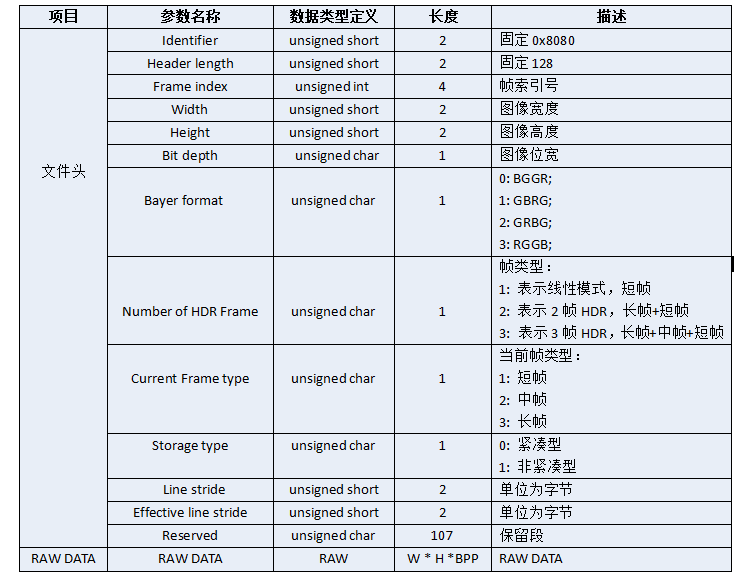
Editable transcription (the original figure already has Chinese labels):
| Parameter name | Type | Length (Byte) | Description |
|---|---|---|---|
| Identifier | unsigned short | 2 | Fixed 0x8080 |
| Header length | unsigned short | 2 | Fixed 128 |
| Frame index | unsigned int | 4 | Frame index |
| Width | unsigned short | 2 | Image width |
| Height | unsigned short | 2 | Image height |
| Bit depth | unsigned char | 1 | Image bit depth |
| Bayer format | unsigned char | 1 | 0: BGGR; 1: GBRG; 2: GRBG; 3: RGGB |
| Number of HDR Frame | unsigned char | 1 | 1: linear, short; 2: HDR2, long+short; 3: HDR3, long+medium+short |
| Current Frame type | unsigned char | 1 | 1 short; 2 medium; 3 long |
| Storage type | unsigned char | 1 | 0 packed; 1 unpacked |
| Line stride | unsigned short | 2 | Bytes |
| Effective line stride | unsigned short | 2 | Bytes |
| Reserved | unsigned char | 107 | Reserved |
| RAW DATA | RAW | W * H * BPP | RAW DATA |
11.3.1.4 RK-RAW V2.0
The RK-RAW V2.0 format consists of a start identifier, a data block, and an end identifier.
Format Block Definition
A data block consists of three parts: identifier ID, block length, and block data. Each identifier ID has a unique fixed value.
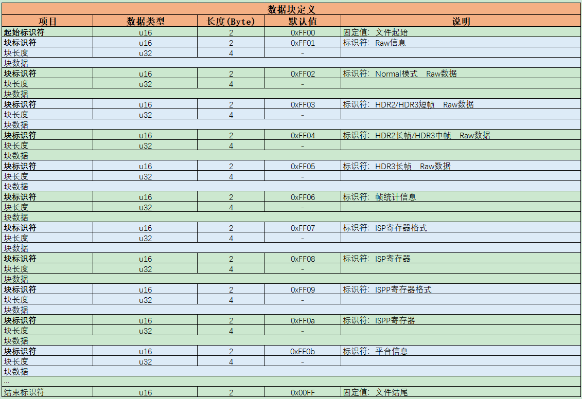
Editable transcription (the original figure already has Chinese labels):
| Item | Type | Length (Byte) | Default | Description |
|---|---|---|---|---|
| Start identifier | u16 | 2 | 0xFF00 | File start |
| Block identifier | u16 | 2 | 0xFF01 | Raw information |
| Block length | u32 | 4 | - | |
| Block data | ||||
| Block identifier | u16 | 2 | 0xFF02 | Normal-mode Raw data |
| Block length | u32 | 4 | - | |
| Block data | ||||
| Block identifier | u16 | 2 | 0xFF03 | HDR2/HDR3 short-frame Raw |
| Block length | u32 | 4 | - | |
| Block data | ||||
| Block identifier | u16 | 2 | 0xFF04 | HDR2 long/HDR3 medium Raw |
| Block length | u32 | 4 | - | |
| Block data | ||||
| Block identifier | u16 | 2 | 0xFF05 | HDR3 long-frame Raw |
| Block length | u32 | 4 | - | |
| Block data | ||||
| Block identifier | u16 | 2 | 0xFF06 | Frame statistics |
| Block length | u32 | 4 | - | |
| Block data | ||||
| Block identifier | u16 | 2 | 0xFF07 | ISP register format |
| Block length | u32 | 4 | - | |
| Block data | ||||
| Block identifier | u16 | 2 | 0xFF08 | ISP registers |
| Block length | u32 | 4 | - | |
| Block data | ||||
| Block identifier | u16 | 2 | 0xFF09 | ISPP register format |
| Block length | u32 | 4 | - | |
| Block data | ||||
| Block identifier | u16 | 2 | 0xFF0a | ISPP registers |
| Block length | u32 | 4 | - | |
| Block data | ||||
| Block identifier | u16 | 2 | 0xFF0b | Platform information |
| Block length | u32 | 4 | - | |
| Block data | ||||
| … | ||||
| End identifier | u16 | 2 | 0x00FF | File end |
Not all blocks in the chart are required, and you can choose a combination of several of them. For example, a RKRawV2 file may contain only ‘Raw Blocks’, ‘Raw Blocks’, and ‘Frame Statistics Blocks’, and we recommend including at least these three blocks because such files are meaningful.
Raw Block Definition
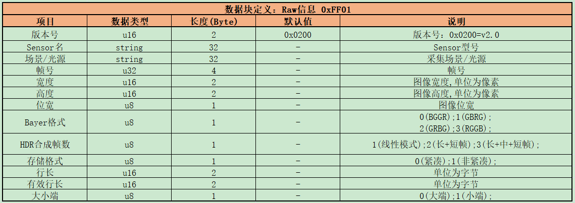
Editable transcription (the original figure already has Chinese labels):
| Item | Type | Length (Byte) | Default | Description |
|---|---|---|---|---|
| Version | u16 | 2 | 0x0200 | 0x0200=v2.0 |
| Sensor name | string | 32 | - | Sensor model |
| Scene/light | string | 32 | - | Capture scene/light source |
| Frame number | u32 | 4 | - | Frame number |
| Width | u16 | 2 | - | Image width, pixels |
| Height | u16 | 2 | - | Image height, pixels |
| Bit depth | u8 | 1 | - | Image bit depth |
| Bayer format | u8 | 1 | - | 0 BGGR; 1 GBRG; 2 GRBG; 3 RGGB |
| HDR frame count | u8 | 1 | - | 1 linear; 2 long+short; 3 long+medium+short |
| Storage format | u8 | 1 | - | 0 packed; 1 unpacked |
| Line stride | u16 | 2 | - | Bytes |
| Effective line stride | u16 | 2 | - | Bytes |
| Endianness | u8 | 1 | - | 0 big-endian; 1 little-endian |
RAW Block Definition
This data segment can store Raw image data, or buffer fd or virtual address pointing to Raw image data. When using the relevant API, you need to pass parameters to indicate the type of data stored in the data block, see rk_aiq_rawbuf_type_t for details.

Editable transcription (the original figure already has Chinese labels):
| Item | Type | Length (Byte) | Description |
|---|---|---|---|
| Raw data | - | heightwidthN; unpacked N=2; packed N=bpp/8 | Raw data, 0xFF02–0xFF05 |
Frame Statistics Block Definition
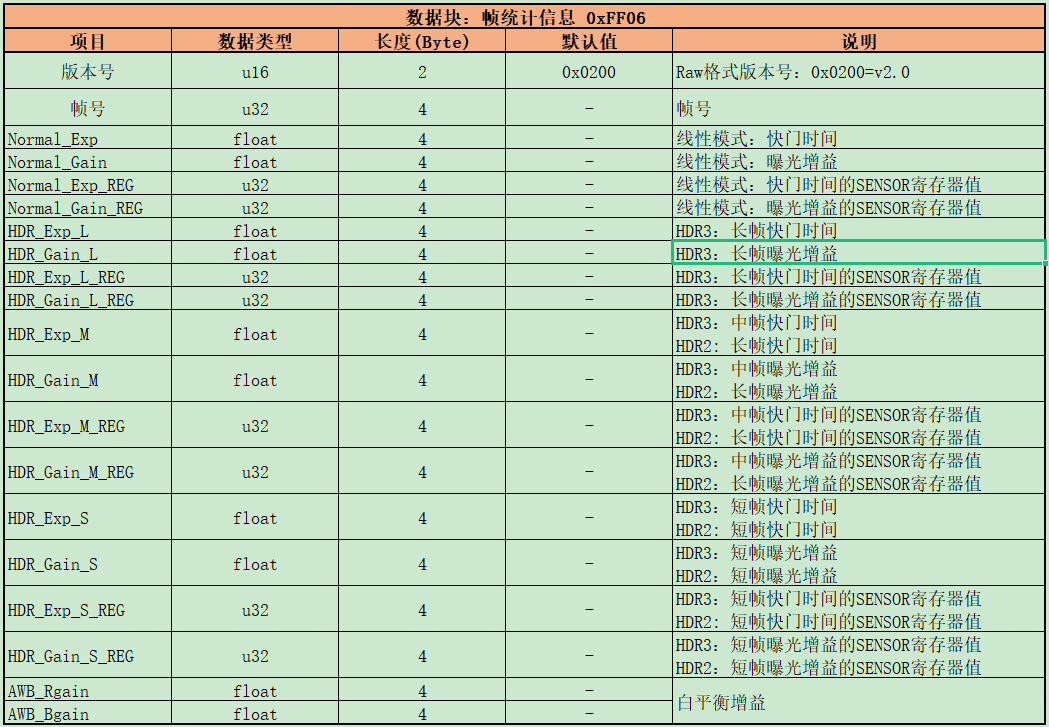
Editable transcription (the original figure already has Chinese labels):
| Item | Type | Length (Byte) | Default | Description |
|---|---|---|---|---|
| Version | u16 | 2 | 0x0200 | Raw: 0x0200=v2.0 |
| Frame number | u32 | 4 | - | Frame number |
| Normal_Exp | float | 4 | - | Linear shutter time |
| Normal_Gain | float | 4 | - | Linear exposure gain |
| Normal_Exp_REG | u32 | 4 | - | Linear shutter SENSOR register |
| Normal_Gain_REG | u32 | 4 | - | Linear gain SENSOR register |
| HDR_Exp_L | float | 4 | - | HDR3 long shutter time |
| HDR_Gain_L | float | 4 | - | HDR3 long gain |
| HDR_Exp_L_REG | u32 | 4 | - | HDR3 long shutter SENSOR register |
| HDR_Gain_L_REG | u32 | 4 | - | HDR3 long gain SENSOR register |
| HDR_Exp_M | float | 4 | - | HDR3 medium/HDR2 long shutter time |
| HDR_Gain_M | float | 4 | - | HDR3 medium/HDR2 long gain |
| HDR_Exp_M_REG | u32 | 4 | - | HDR3 medium/HDR2 long shutter SENSOR register |
| HDR_Gain_M_REG | u32 | 4 | - | HDR3 medium/HDR2 long shutter SENSOR register (source wording; Gain field name conflicts, verify) |
| HDR_Exp_S | float | 4 | - | HDR3/HDR2 short shutter time |
| HDR_Gain_S | float | 4 | - | HDR3/HDR2 short gain |
| HDR_Exp_S_REG | u32 | 4 | - | HDR3/HDR2 short shutter SENSOR register |
| HDR_Gain_S_REG | u32 | 4 | - | HDR3/HDR2 short shutter SENSOR register (source wording; Gain field name conflicts, verify) |
| AWB_Rgain | float | 4 | - | White balance gain |
| AWB_Bgain | float | 4 | - | White balance gain |
Register format block definition

Editable transcription (the original figure already has Chinese labels):
| Item | Type | Length (Byte) | Default | Description |
|---|---|---|---|---|
| Version | u16 | 2 | 0x0200 | 0x0200=v2.0 |
| Frame number | u32 | 4 | - | Register base address (as in figure) |
| Base address | u32 | 4 | - | Register base address |
| Offset address | u32 | 4 | - | Start offset address |
| Count | u32 | 4 | - | Register count |
Register Block Definition

Editable transcription (the original figure already has Chinese labels):
| Item | Type | Length (Byte) | Description |
|---|---|---|---|
| Register data | - | - | Register data, 0xFF08/0xFF0a |
Platform Information Block Definition

Editable transcription (the original figure already has Chinese labels):
| Item | Type | Length (Byte) | Description |
|---|---|---|---|
| Chip model | string | 32 | |
| ISP version | string | 32 | |
| AIQ version | string | 32 |
11.3.2 Raw/YUV data acquisition method
12. Error code
| Error Code | Description |
|---|---|
| 0 | Success |
| -1 | Failed |
| -2 | Invalid parameter |
| -3 | Out of memory |
| -4 | File operation failed |
| -5 | Error with analyzer module |
| -6 | The ISP module error |
| -7 | Error with sensor driver |
| -8 | Thread operation error |
| -9 | IOCTL operation error |
| -10 | Timing error |
| -20 | Timeout |
| -21 | Out of range |
| -255 | Unknown error |
13. Abbreviations
| Abbreviation | Full name |
|---|---|
| CIS | Camera Image Sensor |
| RkAiq | Rockchip Automatical Image Quality |
| ISP | Image Signal Process |
| IQ Tuning | Image Quality Tuning |