
This article preserves the complete technical body (PDF pp.5–46) of the 46-page English V1.1.0 source, with full Chinese and Russian translations. No corresponding Chinese PDF was supplied. All three articles use the 14 original English-PDF figures, retaining Chinese UI labels already present in the originals. Code, comments, APIs, parameters, register values and example constants retain the source text; captions and prose are localized.
The source product scope and OS support are reproduced below. They are source records, not compatibility claims for all current versions. This is an ArmSoM platform reference: verify the actual board, RK3588, Sensor/VCM, ISP30, SDK/BSP, AIQ and kernel versions. No ArmSoM hardware validation was performed. Do not extend the source description of mixed RK/custom libraries to unverified versions. Exposure, gain, focus and motor control can change image capture or hardware state; no code, device configuration or motor operation was executed.
Source caveats: repeated interface descriptions/headings, mixed uapi/uapi2 names, an ISP32 cross-reference, two garbled table descriptions and conflicting window parameters are preserved and recorded. The code is a source example, not a guarantee of compilability. See the editorial notes.
| SoC | Kernel |
|---|---|
| RK3588 | Linux 5.10 |
| SoC | BuildRoot | Debian | Yocto | Android |
|---|---|---|---|---|
| RK3588 | Y | N | N | Y |
Source and adaptation caveats: EDITORIAL-NOTES. ArmSoM · Rockchip Linux
1 Overview
This document mainly introduces the implementation of 3A libraries, aiming to guide users on how to implement customized 3A algorithm libraries.
The 3A algorithm library depends on AIQ, which already contains the 3A algorithm library of RK and is enabled by default. Users can implement customized 3A libraries according to this document as needed.
1.1 Design ideas
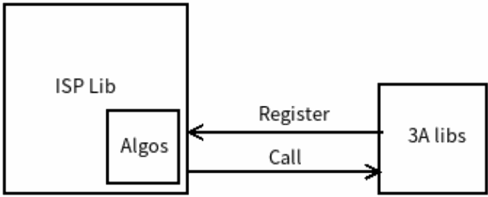
The basic design idea is shown in the following figure:
Technical figure from the English source, PDF p.5.
The 3A library is registered with the ISP library by registration, note that the 3A library of RK has been implicitly registered, and does not require the user to display the registration
After the 3A library is registered with the ISP library, after the ISP library gets the 3A statistics from the driver, it calls back to the 3A library interface to get the new 3A parameters, and the ISP library sets the new 3A parameters to the driver
1.2 File organization
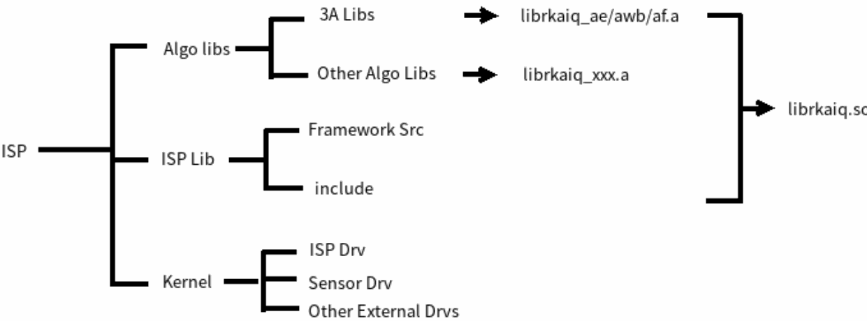
The file organization is shown in the following figure:
Technical figure from the English source, PDF p.6.
ISP Firmware is divided into application layer librkaiq.so and driver layer ISP drivers and peripheral drivers, including Sensor, VCM and Flashlight
librkaiq.so contains many algorithm libraries, such as 3A algorithm library, HDR algorithm library, etc., the algorithm library exists in the form of static library, and finally links form librkaiq.so. Except for the librkaiq_ae/awb/af.a 3A library, which does not provide source code, the source code of other basic libraries is open.
The algorithm library of all modules supported by the framework uses the client algorithm, but in general, except for the 3A library that wants to be customized, other basic libraries can use the default library provided by RK.
1.3 Development mode
The following three development modes are supported:
3A library uses the RK library. When using this method, RK’s 3A library APIs can be used, including: rk_aiq_user_api2_ae.h, rk_aiq_user_api2_af.h, and rk_aiq_user_api2_awb.h.
3A library partly uses RK library and part uses user-defined library. For example, the AE library uses a custom library, and the AWB library uses the RK library.
3A library custom library and RK library are used at the same time. For example, when the AE library and the RK library run at the same time, the RK AE library will be run first, and then the custom AE library will be run, and the custom library result will overwrite the RK AE library result. This mode is used to simplify the development of custom libraries, which do not need to output all the results required by the AIQ framework, and some of the results can be exported by the RK AE library.
1.4 Software processes
1.4.1 Basic processes
The RK 3A algorithm does not require user display registration, which is implicitly registered within the AIQ framework. Custom 3A algorithm registration, taking custom AE algorithm registration as an example, the example pseudocode is as follows:
// Initialize the usage scenario, not required, defaults to normal, day, which is used to select scene parameters in the JSON IQ file
if (work_mode == RK_AIQ_WORKING_MODE_NORMAL)
        ret = rk_aiq_uapi2_sysctl_preInit_scene(sns_entity_name, "normal",
"day");
  else
        ret = rk_aiq_uapi2_sysctl_preInit_scene(sns_entity_name, "hdr", "day");
// Depending on whether the usage pattern is surround view or single camera, initialize Group Ctx or AIQ ctx
   if (!group_mode)
        ctx->aiq_ctx = rk_aiq_uapi2_sysctl_init(sns_entity_name, ctx->iqpath,
NULL, NULL);
  else {
       rk_aiq_camgroup_instance_cfg_t camgroup_cfg;
       memset(&camgroup_cfg, 0, sizeof(camgroup_cfg));
       camgroup_cfg.sns_num = 1;
       camgroup_cfg.sns_num++;
       camgroup_cfg.sns_ent_nm_array[0] = sns_entity_name;
       camgroup_cfg.sns_ent_nm_array[1] = sns_entity_name2;
       camgroup_cfg.config_file_dir = ctx->iqpath;
       camgroup_cfg.overlap_map_file = "srcOverlapMap.bin";
       ctx->camgroup_ctx = rk_aiq_uapi2_camgroup_create(&camgroup_cfg);
  }
// If you need to register a custom AE algorithm, register a custom AE callback
  rk_aiq_customeAe_cbs_t cbs = {
                           .pfn_ae_init = custom_ae_init,
                           .pfn_ae_run = custom_ae_run,
                           .pfn_ae_ctrl = custom_ae_ctrl,
                           .pfn_ae_exit = custom_ae_exit,
                       };
  rk_aiq_uapi2_customAE_register((const rk_aiq_sys_ctx_t*)(ctx->camgroup_ctx),
&cbs);
// If you need to run a third-party AE algorithm, enable the custom AE algorithm. Third-party AE library registration interface, single camera and surround view shared.
//In the current AIQ version, both the default RK algorithm and the third-party algorithm will run, and if necessary, you can call rk_aiq_uapi2_sysctl_enableAxlib to force off RK AE.
  rk_aiq_uapi2_customAE_enable((const rk_aiq_sys_ctx_t*)(ctx->camgroup_ctx),
true);
// Prepare the ISP pipeline and configure initialization parameters such as ISP and Sensor
// If necessary, you can call the module API before prepare to modify the module initialization parameters, otherwise the initialization parameters are specified by the IQ file, or are specified by hard code in AIQ, or the chip reset value
 if (!group_mode) {
      rk_aiq_uapi2_sysctl_prepare(ctx->aiq_ctx, ctx->width, ctx->height,
work_mode);
      rk_aiq_uapi2_sysctl_start(ctx->aiq_ctx );
 } else {
      rk_aiq_uapi2_camgroup_prepare(ctx->camgroup_ctx, work_mode);
      ret = rk_aiq_uapi2_camgroup_start(ctx->camgroup_ctx);
 }
// Turn on the VI data flow and note that no AIQ library interfaces are called in this section.
start_capturing(ctx);
......
// AIQ internal thread loop work: obtain 3A statistics from the driver, call each algorithm library to calculate new ISP parameters, sensor parameters, etc., and issue new parameters to ISP drivers and sensor drivers.
// This procedure calls the API to set parameters for each algorithm module
......
// Stop the data flow first on exit
stop_capturing(ctx);
// Stop AIQ ctx or Group ctx
 if (!group_mode)
       rk_aiq_uapi2_sysctl_stop(ctx->aiq_ctx, false);
else
       rk_aiq_uapi2_camgroup_stop(ctx->camgroup_ctx);
// Anti-register third-party AEs
 rk_aiq_uapi2_customAE_unRegister(ctx->aiq_ctx);
// Deinitialize AIQ ctx or Group ctx
 if (!group_mode)
        rk_aiq_uapi2_sysctl_deinit(ctx->aiq_ctx);
else
       rk_aiq_uapi2_camgroup_destroy(ctx->camgroup_ctx);
1.4.2 Internal operational processes
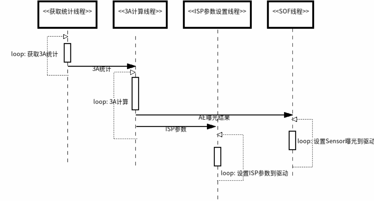
The internal operation of AIQ is shown in the following figure:
Technical figure from the English source, PDF p.9.
Get statistics thread: This thread continuously fetches 3A statistics from the ISP driver and sends them to the 3A calculation thread.
3A calculation thread: After receiving the statistics, the thread starts to call the module algorithm (including third-party algorithm callbacks), calculates new parameters, and then sends the new parameters to the ISP parameter setting thread and the SOF thread.
ISP parameter setting thread: After receiving a new ISP parameter setting request, the thread sends it to the ISP driver at the appropriate time.
SOF thread: This thread is the response function of the Sensor frame header event, which receives a new exposure setting request and takes the new exposure parameter setting from the queue to the Sensor driver.
2 Developer Guide
2.1 AE algorithm registration
The AE algorithm registration process involves algorithm registration, algorithm enablement, algorithm deregistration, registration and invocation of rk_aiq_uapi_customAE_register interfaces, enabling rk_aiq_uapi_customAE_enable interfaces, and deregistration of invocation rk_aiq_uapi_customAE_unRegister interfaces
2.1.1 rk_aiq_uapi2_customAE_register
【Description】 Register the AE algorithm library
【Grammar】
XCamReturn
rk_aiq_uapi2_customAE_register(const rk_aiq_sys_ctx_t* ctx,
rk_aiq_customeAe_cbs_t* cbs)
【Parameters】
| Parameter Name |
Description | Input/Output |
|---|---|---|
| ctx | AIQ context pointer for single-camera and surround view applications |
input |
| cbs | Callback function pointer |
【Return Value】
| Return value | Description |
|---|---|
| 0 | Success |
| Non-0 | Failure, see Error Code Table |
2.1.2 rk_aiq_uapi2_customAE_enable
【Description】 Register the AE algorithm library
【Grammar】
XCamReturn
rk_aiq_uapi2_customAE_enable(const rk_aiq_sys_ctx_t* ctx, bool enable);
【Parameters】
| Parameter Name |
Description | Input/Output |
|---|---|---|
| ctx | AIQ context pointer for single-camera and surround view applications |
input |
| enable | AE algorithm enable bit | input |
【Return Value】
| Return value | Description |
|---|---|
| 0 | Success |
| Non-0 | Failure, see Error Code Table |
2.1.3 rk_aiq_uapi2_customAE_unRegister
【Description】 Register the AE algorithm library
【Grammar】
XCamReturn
rk_aiq_uapi2_customAE_unRegister(const rk_aiq_sys_ctx_t* ctx);
【Parameters】
| Parameter Name |
Description | Input/Output |
|---|---|---|
| ctx | AIQ context pointer for single-camera and surround view applications |
Input |
【Return Value】
| Return value | Description |
|---|---|
| 0 | Success |
| Non-0 | Failure, see Error Code Table |
2.1.4 Callback functions and data types
Users need to implement the following callback functions in the self-developed custom AE library:
rk_aiq_customeAe_cbs_t cbs = {
.pfn_ae_init = custom_ae_init,
.pfn_ae_run = custom_ae_run,
.pfn_ae_ctrl = custom_ae_ctrl,
.pfn_ae_exit = custom_ae_exit,
};
| Member name |
Description |
|---|---|
| pfn_ae_init | Initialize the callback function pointer of AE |
| pfn_ae_run | Run AE’s callback function pointer |
| pfn_ae_ctrl | Pointer to the callback function that controls the internal state of AE [This parameter is temporarily invalid] |
| pfn_ae_exit | Destroys AE’s callback function pointer |
2.1.4.1 custom_ae_init
【Description】 Initialize the AE algorithm library
【Grammar】
int32_t custom_ae_init(void* ctx);
【Parameters】
| Parameter Name |
Description | Input/Output |
|---|---|---|
| ctx | AIQ context pointer for single-camera and surround view applications |
Input |
【Return Value】
| Return value | Description |
|---|---|
| 0 | Success |
| Non-0 | Failure, see Error Code Table |
2.1.4.2 custom_ae_run
【Description】 Run the AE algorithm library to calculate the exposure time and gain of the sensor, the digital gain of the ISP, and update the hardware configuration parameters
【Grammar】
int32_t custom_ae_run(void* ctx, const rk_aiq_customAe_stats_t* pstAeInfo,
                      rk_aiq_customeAe_results_t* pstAeResult);
【Parameters】
| Parameter Name |
Description | Input/Output |
|---|---|---|
| ctx | AIQ context pointer for single-camera and surround view applications |
Input |
| pstAeInfo | Input a data parameter pointer containing AE hardware statistics and their synchronized exposure information Input |
|
| pstAeResult | Output algorithm result pointer containing exposure result parameters of sensor and update hardware configuration parameters |
Output |
【Return Value】
| Return value | Description |
|---|---|
| 0 | Success |
| Non-0 | Failure, see Error Code Table |
2.1.4.3 custom_ae_ctrl
【Description】 Change the internal state of the algorithm library and cannot be used temporarily
【Grammar】
int32_t custom_ae_ctrl(void* ctx, uint32_t u32Cmd, void *pValue);
【Parameters】
| Parameter Name |
Description | Input/Output |
|---|---|---|
| ctx | AIQ context pointer for single-camera and surround view applications |
Input |
【Return Value】
| Return value | Description |
|---|---|
| 0 | Success |
| Non-0 | Failure, see Error Code Table |
2.1.4.4 custom_ae_exit
【Description】 Unregister the AE algorithm library
【Grammar】
int32_t custom_ae_exit(void* ctx);
【Parameters】
| Parameter Name |
Description | Input/Output |
|---|---|---|
| ctx | AIQ context pointer for single-camera and surround view applications |
Input |
【Return Value】
| Return value | Description |
|---|---|
| 0 | Success |
| Non-0 | Failure, see Error Code Table |
2.1.5 Enter data parameters
【Description】
Third-party AE input data parameters include image luminance statistics and corresponding exposure parameter values, which are compatible with single camera and surround view applications. 【Definition】
#define RK_AIQ_MAX_HDR_FRAME (3)
typedef struct rk_aiq_customAe_stats_s
{
    //hw stats
    Aec_Stat_Res_t rawae_stat[RK_AIQ_MAX_HDR_FRAME]; // before awb gain
    Aec_Stat_Res_t extra; // after awb gain, lsc, TMO
    //exposure
    RkAiqExpParamComb_t linear_exp;
    RkAiqExpParamComb_t hdr_exp[RK_AIQ_MAX_HDR_FRAME];
    struct rk_aiq_customAe_stats_s* next; // for surround view(multiple cams)
} rk_aiq_customAe_stats_t;
【Members】
| Member Name | Description |
|---|---|
| rawae_stat[RK_AIQ_MAX_HDR_FRAME] | Based on the pre-hardware statistics of RAW images, up to 3 frames of RAW images can be counted. In linear exposure mode, only rawae_stat [0] is valid, and in HDR exposure mode, rawae_stat [0-2] represent hardware statistics for short, medium, and long frames |
| extra | Post-facing hardware statistics based on RAW images, HDR mode: represents the hardware statistics of composite frames |
| linear_exp | Exposure parameters in linear mode, synchronized with hardware statistics |
| hdr_exp[RK_AIQ_MAX_HDR_FRAME] | The exposure parameters in HDR mode are synchronized with the hardware statistics, where 0~2 represents the exposure parameters of short, medium, and long frames, respectively |
| next | The pointer is valid only in surround view multi-camera applications, the pointer points to the input data parameters of the next camera, and the corresponding input parameter members of each camera are the same |
【Description】
Input data parameters are divided into two types of parameters, namely the hardware statistics of the image and the exposure parameters corresponding to the image
The input data parameters can be compatible with single camera and surround view multi-camera applications, and the input data parameters of multiple cameras can be obtained through the next pointer
The hardware statistics data type of the image is Aec_Stat_Res_t, and the exposure information data type is RkAiqExpParamComb_t, and the data type description is detailed in the Rockchip_Development_Guide_ISP30 document
RK_AIQ_MAX_HDR_FRAME indicates that RK supports up to 3 frames of HDR
2.1.6 Output algorithm result parameters
【Description】
Third-party AE output parameters include exposure parameters, hardware parameters, etc., and are compatible with single camera and surround view applications
【Definition】
#define RK_AIQ_MAX_HDR_FRAME (3)
typedef struct rk_aiq_i2c_data_s {
    bool bValid;
    unsigned int nNumRegs;
    unsigned int* pRegAddr;
    unsigned int* pRegValue;
    unsigned int* pDelayFrames;
} rk_aiq_i2c_data_t;
typedef struct rk_aiq_customeAe_results_singel_s
{
    //exposure result (including:reg value & real value)
    RkAiqExpParamComb_t linear_exp;
    RkAiqExpParamComb_t hdr_exp[RK_AIQ_MAX_HDR_FRAME];
    rk_aiq_i2c_data_t exp_i2c_params;
    //hw result
    struct window meas_win;
    unsigned char meas_weight[15 * 15];
    struct rk_aiq_customeAe_results_singel_s* next; // for surround view(multiple
cams)
} rk_aiq_customeAe_results_single_t;
typedef struct rk_aiq_customeAe_results_s
{
    //exposure result (including:reg value & real value)
    RkAiqExpParamComb_t linear_exp;
    RkAiqExpParamComb_t hdr_exp[RK_AIQ_MAX_HDR_FRAME];
    rk_aiq_i2c_data_t exp_i2c_params;
    //hw result
    struct window meas_win;
    unsigned char meas_weight[15 * 15];
    RkAiqIrisParamComb_t Iris;
    uint32_t frame_length_lines;
    bool is_longfrm_mode;
    struct rk_aiq_customeAe_results_singel_s* next; // for surround view(multiple
cams)
} rk_aiq_customeAe_results_t;
【Members】
| Member Name | Child members | Description |
|---|---|---|
| linear_exp | exp_real_params exp_sensor_params |
Exposure parameters in linear mode, containing the actual exposure value (exp_real_params) and the registered value in RK format (exp_sensor_params) |
| hdr_exp[RK_AIQ_MAX_HDR_FRAME] | exp_real_params exp_sensor_params |
The exposure parameters in HDR mode include the actual value of exposure (exp_real_params) and the register value of RK format (exp_sensor_params), where 0~2 represents the exposure parameters of short, medium and long frames, respectively, for HDR2 frame compositing, 0 and 1 elements are valid, for HDR3 frame compositing, 0-2 are valid |
| exp_i2c_params | bValid nNumRegs pRegAddr pRegValue pDelayFrames |
i2c register value parameter is set with the exp_i2c_params parameter when bValid is true, and the above linear_exp or hdr_ when bValid is false The RK format register value parameter in exp is used to set the register |
| frame_length_lines | The VTS value of the sensor, which is related to the frame rate setting |
|
| is_longfrm_mode | Long frame mode enable bit true: enable long frame mode; false: Turn off long frame mode , this parameter is only valid in HDR mode |
|
| Iris | PIris DCIris | Aperture setting parameters, including P aperture and DC aperture setting parameters |
| meas_win | h_offs v_offs h_size v_size |
The hardware statistics window area parameter h/v_offs indicates the horizontal and vertical offset of the upper-left vertex of the window relative to the upper- left vertex of the photosensitive area. h/v_size indicates the dimensions of the window in the horizontal and vertical directions, respectively |
| meas_weight | Hardware statistical weight parameters, including 15X15 weight parameters, the value range is 0~32 |
|
| next | For non-surround view applications, the pointer needs to be empty; Looking around the application, if multiple cameras need to set the same algorithm result, the pointer needs to be empty, only the members in the rk_aiq_customeAe_results_t need to be set, and then all cameras use the algorithm result in the rk_aiq_customeAe_results_t as their final result; If multiple cameras need to set different algorithm results, the user needs to apply for the next pointer memory and add the algorithm result of the next camera |
【Precautions】
Output algorithm results, compatible with single-camera applications and surround view multi-camera applications. In surround-view multi-camera applications, it can be compatible with single algorithm results and multiple algorithm results.
meas_win the window area parameters for AE hardware statistics, hardware statistics (tile brightness, histogram) will expand based on the window area. For HDR multi-frame exposure applications, the hardware statistics window is the same by default for all frames.
meas_weight is the weight parameter required for weighted histogram statistics, generally consistent with the weight (software weight) used for the weighted mean of tile-weighted luminance
When setting the exposure, you need to configure the actual exposure value and the corresponding register value. The actual exposure value includes: exposure time (unit: seconds), exposure gain (unit: multiple), DCG state (0:LCG, 1:HCG), for other algorithm modules; The exposure register value is the register value that interfaces with the sensor and supports RK format and third-party formats.
When setting the exposure register value, RK format and third-party format are supported. The register value of RK format does not need to be set by the customer, and it is internally converted according to the actual value of exposure, and the bValid value in the exp_i2c_params is required to be false; Third-party formats require the user to set the required register value and corresponding address, and require the bValid value in the exp_i2c_params to be true.
For surround view applications, if all cameras in surround view need to set the same exposure and hardware values, only set the parameters in the rk_aiq_customeAe_results_t, the next pointer is empty; If each camera in the surround view needs to set different exposures and hardware, you need to set the result values in order, allocate memory for the next pointer to point to the next camera algorithm result. It should be noted that there are differences between rk_aiq_customeAe_results_t and the parameters in the rk_aiq_customeAe_results_single_t, the former has more individual result parameters than the two, which is a public parameter and all cameras are set to the same value by default.
The hardware statistics data type for the image is Aec_Stat_Res_t, the RK exposure information data type is RkAiqExpParamComb_t, and the RK aperture parameter data type is RkAiqIrisParamComb_t. For details about the above data types, see the Rockchip_Development_Guide_ISP30 document.
2.2 AWB algorithm registration
The RK AWB algorithm implements a rk_aiq_uapi_customAWB_register registration function, and the user calls the registration function to register the Custom AWB algorithm with the ISP, the example is similar to the AE algorithm library registration, and the Custom AWB algorithm is enabled through the rk_aiq_uapi_customAWB_enable.
Note: For a smooth transplant, it is recommended to review:
(1) The following content of the “Rockchip_Color_Optimization_Guide” document,
(a) “2 AWB/2.1 Function Description” section content and AWB flowchart content
(b) AWB white spot detection flowchart in the section “2 AWB/2.2 White Spot Detection Process for Key Parameters/Hardware”
(2) “Statistics / Data Types / rk_aiq_isp_awb_stats2_v3x_t” section of Rockchip_Development_Guide_ISP30
2.2.1 API
2.2.1.1 rk_aiq_uapi_customAWB_register
【Description】 Custom AWB algorithm registration.
【Grammar】
XCamReturn
rk_aiq_uapi_customAWB_register(const rk_aiq_sys_ctx_t* ctx,
rk_aiq_customeAwb_cbs_t* cbs);
【Parameters】
| Parameter Name |
Description | Input/Output |
|---|---|---|
| ctx | AIQ context pointer | Input |
| cbs | For the callback function registered by the Custom AWB algorithm with the ISP library, refer to the rk_aiq_customeAwb_cbs_t structure description below Input |
【Return Value】
| Return value | Description |
|---|---|
| 0 | Success |
| Non-0 | Failure, see Error Code Table |
【Note】
You must first call rk_aiq_uapi_sysctl_init to initialize the AIQ context pointer ctx.
【Requirements】
Header file: rk_aiq_user_api_custom_awb.h
Library file: librkaiq.so
2.2.1.2 rk_aiq_uapi_customAWB_enable
【Description】 Custom AWB algorithm enabled.
【Grammar】
XCamReturn
rk_aiq_uapi_customAWB_enable(const rk_aiq_sys_ctx_t* ctx, bool enable);
【Parameters】
| Parameter Name | Description | Input/Output |
|---|---|---|
| ctx | AIQ context pointer | Input |
| enable | Custom AWB enable switch value: true / false default: false |
Input |
【Return Value】
| Return value | Description |
|---|---|
| 0 | Success |
| Non-0 | Failure, see Error Code Table |
【Note】
Called after rk_aiq_uapi_customAWB_register has completed the Custom AWB algorithm registration.
【Requirements】
Header file: rk_aiq_user_api_custom_awb.h
Library file: librkaiq.so
2.2.1.3 rk_aiq_uapi_customAWB_unRegister
【Description】 Custom AWB algorithm logout.
【Grammar】
XCamReturn
rk_aiq_uapi_customAWB_unRegister(const rk_aiq_sys_ctx_t* ctx);
【Parameters】
| Parameter Name | Description | Input/Output |
|---|---|---|
| ctx | AIQ context pointer | Input |
【Return Value】
| Return value | Description |
|---|---|
| 0 | Success |
| Non-0 | Failure, see Error Code Table |
【Note】
Called after rk_aiq_uapi_customAWB_register has completed the Custom AWB algorithm registration.
【Requirements】
Header file: rk_aiq_user_api_custom_awb.h
Library file: librkaiq.so
2.2.2 Data types
2.2.2.1 A callback function registered with the ISP library
2.2.2.1.1 rk_aiq_customeAwb_cbs_t
【Description】 Defines the callback function that the Custom AWB algorithm registers with the ISP library.
【Definition】
typedef struct rk_aiq_customeAwb_cbs_s
{
    int32_t (*pfn_awb_init)(void* ctx);
    int32_t (*pfn_awb_run)(void* ctx, const rk_aiq_customAwb_stats_t* pstAwbInfo,
rk_aiq_customeAwb_results_t* pstAwbResult);
    int32_t (*pfn_awb_run)(void* ctx, uint32_t u32Cmd, void *pValue);
    int32_t (*pfn_awb_exit)(void* ctx);
} rk_aiq_customeAwb_cbs_t;
【Member】
| Member name |
Description |
|---|---|
| pfn_awb_init | After initialization , the first initialization is called by the AwbDemoPrepare function |
| pfn_awb_ctrl | Callback function pointers that control the internal state of Custom AWB are not currently supported. |
| pfn_awb_run | Refer to the instructions below for the callback function pointer rk_aiq_customAwb_stats_t and rk_aiq_customeAwb_results_t to run Custom AWB. If pstAwbResult==nullptr is represented as initialization, it is used to configure the pstAwbResult at initialization, otherwise you need to implement the function of calculating pstAwbResult based on the statistics pstAwbInfo. If it is surround view mode, and all camera configuration parameters are the same, you can implement it as described above, otherwise you need to configure pstAwbResult- >next (corresponding to the first camera), pstAwbResult->next->next (corresponding to the second camera), and all cameras (Note: pstAwbResult corresponds to the configuration of the 0th camera). |
| pfn_awb_exit | The freed requested memory, etc . is called by AwbDemoDestroyCtx |
【Note】
Users need to implement the above callback functions in the custom AWB library.
pfn_awb_run implement pseudocode in custom_awb_run functions that can be referred to third_party_awb_algo.cpp
2.2.2.2 Statistics
2.2.2.2.1 rk_aiq_customAwb_stats_t
【Description】 Defines white balance hardware statistics obtained by the Custom AWB algorithm.
【Definition】
typedef struct rk_aiq_customAwb_stats_s
{
    rk_aiq_awb_stat_wp_res_light_v201_t light[RK_AIQ_AWB_MAX_WHITEREGIONS_NUM];
    int WpNo2[RK_AIQ_AWB_MAX_WHITEREGIONS_NUM];
    rk_aiq_awb_stat_blk_res_v201_t blockResult[RK_AIQ_AWB_GRID_NUM_TOTAL];
    rk_aiq_awb_stat_wp_res_light_v201_t multiwindowLightResult[4];
    rk_aiq_awb_stat_wp_res_v201_t
excWpRangeResult[RK_AIQ_AWB_STAT_WP_RANGE_NUM_V201];
    unsigned int WpNoHist[RK_AIQ_AWB_WP_HIST_BIN_NUM];
    struct rk_aiq_customAwb_stats_s* next;
} rk_aiq_customAwb_stats_t;
【Member】
| Member name | Description |
|---|---|
| light | White point statistics for different light sources under the main window, up to RK_AIQ_AWB_MAX_WHITEREGIONS_NUM light sources. |
| WpNo2 | The number of white points at the intersection of the XY domain and the UV domain under different light sources in the main window, without decimal places. |
| blockResult | The RGB accumulation image for each block is evenly tiled in a total of 15x15 (RK_AIQ_AWB_GRID_NUM_TOTAL) blocks. |
| multiwindowLightResult | White point statistics under different light sources in several sub-windows (only the first 4 light sources are recorded, all light sources can be recorded by time division multiplexing method), up to 4 sub-windows. |
| excWpRangeResult | Statistics of points that fall in the excludeWpRange region (only the first four regions of excludeWpRange are recorded), up to 4 regions. |
| WpNoHist | The number of white dots per bin in the white point histogram, no decimal places; Whether the white point of the XY box or the box in XY is counted is determined by the register xyRangeTypeForWpHist. |
| next | Useful only in surround view multi-camera applications, the pointer points to the white balance hardware statistics of the next camera. |
【Note】
For details of each member, see the “Statistics/Data Types” section of Rockchip_Development_Guide_ISP30 rk_aiq_isp_awb_stats2_v3x_t Definition of Structure Members.
2.2.2.3 The result of the operation
2.2.2.3.1 rk_aiq_customeAwb_results_t
【Description】 Define the configuration parameters and calculation results of the Custom AWB algorithm.
【Definition】
typedef struct rk_aiq_customeAwb_results_s
{
    bool IsConverged; true: converged; false: not converged
    rk_aiq_wb_gain_t awb_gain_algo;
    float awb_smooth_factor;
    rk_aiq_customAwb_hw_cfg_t awbHwConfig;
    rk_aiq_customeAwb_single_results_t *next;//defalut vaue is nullptr,which means all cameras with the same cfg;
} rk_aiq_customeAwb_results_t;
【Member】
| Member name | Description |
|---|---|
| IsConverged | characterize whether the current AWBgain converges; true converged, false unconverged; Default value: false; Must be configured. |
| awb_gain_algo | The gain of the R, GR, GB, B color channels derived by the Custom AWB algorithm; Default value: {1.0, 1.0, 1.0, 1.0}, no white balance correction; Must be configured. |
| awb_smooth_factor | The inter-frame smoothing factor provided to CCM and LSC, with larger values and smaller weights for the current frame; value range: [0,1]; Default value: 0.5; can be left unconfigured. |
| awbHwConfig | Hardware configuration parameters for the Custom AWB algorithm; Most parameters and module-related parameters need to be configured correctly, and other parameters have been configured with default values, which can not be updated; See the rk_aiq_customAwb_hw_cfg_t structure description below for details. |
| next | No need to worry about non-surround viewing. If multiple cameras need to set the same algorithm result, the pointer needs to be empty, and then all cameras use the algorithm result in rk_aiq_customeAwb_results_t as their final result, if multiple cameras need to set different rk_aiq_customeAwb_single_results_t member results, the user needs to apply for next pointer memory, add the rk_aiq_customeAwb_single_results_t result of the next camera, then the member value corresponding to next will replace the member value in rk_aiq_customeAwb_results_t. rk_aiq_customeAwb_single_results_t definitions are described below. |
2.2.2.3.2 rk_aiq_customeAwb_single_results_t
【Description】 Define the configuration parameters and calculation results of each camera in the surround view mode of the Custom AWB algorithm, and non-surround view do not need to care
【Definition】
typedef struct rk_aiq_customeAwb_single_results_s
{
    rk_aiq_wb_gain_t awb_gain_algo;//for each camera
    rk_aiq_customAwb_single_hw_cfg_t awbHwConfig;//for each camera
    struct rk_aiq_customeAwb_single_results_s *next;
} rk_aiq_customeAwb_single_results_t;
【Member】
| Member name |
Description |
|---|---|
| awb_gain_algo | Meaning of awb_gain_algo member in the same rk_aiq_customeAwb_results_s |
| awbHwConfig | This struct member has the same meaning as the member with the same name in the awbHwConfig struct in the rk_aiq_customeAwb_results_s |
| next | Useless, meaning of anext member in the same rk_aiq_customeAwb_results_s |
2.2.2.3.3 rk_aiq_wb_gain_t
See Rockchip_Development_Guide_ISP32 “AWB/Function-Level API/Data Type” section rk_aiq_wb_gain_t Struct definition.
2.2.2.3.4 rk_aiq_customAwb_hw_cfg_t
【Description】 Define hardware configuration parameters for the Custom AWB algorithm, main window multi-window configuration, statistical frame selection, etc.
【Definition】
typedef struct rk_aiq_customAwb_hw_cfg_s {
    bool awbEnable;
    bool lscBypEnable;
    uint8_t frameChoose;
    unsigned short windowSet[4];
    unsigned char lightNum;
    unsigned short maxR;
    unsigned short minR;
    unsigned short maxG;
    unsigned short minG;
    unsigned short maxB;
    unsigned short minB;
    unsigned short maxY;
    unsigned short minY;
    bool uvDetectionEnable;
    rk_aiq_awb_uv_range_para_t uvRange_param[RK_AIQ_AWB_MAX_WHITEREGIONS_NUM];
    bool xyDetectionEnable;
    rk_aiq_rgb2xy_para_t rgb2xy_param;
    rk_aiq_awb_xy_range_para_t xyRange_param[RK_AIQ_AWB_MAX_WHITEREGIONS_NUM];
    bool threeDyuvEnable;
    unsigned short threeDyuvIllu[RK_AIQ_AWB_YUV_LS_PARA_NUM];
    short icrgb2RYuv_matrix[12];
    rk_aiq_awb_rt3dyuv_range_para_t
ic3Dyuv2Range_param[RK_AIQ_AWB_YUV_LS_PARA_NUM];
    bool multiwindow_en;
    unsigned short multiwindow[RK_AIQ_AWB_MULTIWINDOW_NUM_V201][4];
} rk_aiq_customAwb_hw_cfg_t;
【Member】
| Member name | Description |
|---|---|
| awbEnable | AWB statistics enable switch; true enabled, false not enabled; Default value: true. |
| lscBypEnable | LSC bypass enable switch for AWB statistical pathway: true enabled (without LSC), false not enabled (via LSC), default value: false. |
| frameChoose | The input frame of AWB hardware statistics can be selected in the value range of {0,1,2}, which means short, medium, and long frames, respectively, and the default value is 0 in linear mode and 1 in wide dynamic range mode. |
| windowSet | AWB statistics main window configuration; windowSet=[h_offset,v_offset,h_size,v_size],h: horizontal, v: vertical; Value range: [0x0, 0xfff]; h_size* v_size must be less than 5120*2880; default value: {0, 0, RawWidth, RawHeight}, full window, if you do not change the window, no configuration is required. |
| lightNum | The number of light sources to be counted, the value range: [0, 7], and the default value: 7. It needs to be configured according to the number of light sources used during calibration, and the calibration tool will output. |
| maxR | When the RGB domain counts white point information, the upper limit of the R channel detected by white point detection; value range: [0x0, 0xff]; default value: 230. |
| minR | When the RGB domain counts the white point information, the lower limit of the R channel for white point detection; value range: [0x0, 0xff]; Default value: 3. |
| maxG | When the RGB domain counts the white point information, the upper limit of the G channel detected by the white point; value range: [0x0, 0xff]; default value: 230. |
| minG | When the RGB domain counts the white point information, the lower limit of the G channel of white point detection; value range: [0x0, 0xff]; Default value: 3. |
| maxB | When the RGB domain counts the white point information, the upper limit of the B channel of white point detection; value range: [0x0, 0xff]; default value: 230. |
| minB | When the RGB domain counts the white point information, the lower limit of the B channel of white point detection; value range: [0x0, 0xff]; Default value: 3. |
| maxY | When the RGB domain counts the white point information, the upper limit of the Y channel detected by the white point; value range: [0x0, 0xff]; default value: 230. |
| minY | When the RGB domain counts the white point information, the lower limit of the Y channel of white point detection; value range: [0x0, 0xff]; Default value: 3. |
| uvDetectionEnable | UV domain white point detection enable switch, true enabled (points within the UV domain white point range are white points), false is not enabled (all points are white points), default value: true. |
| uvRange_param | The UV domain quadrilateral white spot area limit parameter supports up to 7 light sources, and the module- related parameter must be configured correctly when uvDetectionEnable is set to ture, and the unspecified parameters can be obtained by the calibration tool, see the rk_aiq_awb_uv_range_para_t structure description below. |
| xyDetectionEnable | XY domain white point detection enable switch, true enabled (points within the XY domain white point interval are white dots), false is not enabled (all vertices are white dots), default value: true. |
| rgb2xy_param | RGB domain to XY domain conversion parameters, module-related, must be configured correctly when xyDetectionEnable is true, and unspecified parameters that can be obtained from the calibration tool are described in the rk_aiq_rgb2xy_para_t struct description below. |
| xyRange_param | The XY domain quadrilateral white dot area limit parameter supports up to 7 light sources, and the module must be configured correctly when xyDetectionEnable is true, and the unspecified parameters can be obtained by the calibration tool, see the rk_aiq_awb_xy_range_para_t structure description below. |
| threeDyuvEnable | YUV domain white point detection enable switch, true enabled, false not enabled, default value: true. |
| threeDyuvIllu | The value range is [0, 7], 7 indicates that the YUV white point detection is disabled (all points are white points), and other numbers indicate that the corresponding light source is enabled, and the default value is {7, 7, 7, 7}. |
| icrgb2RYuv_matrix | RGB domain to YUV domain rotation matrix parameters;related to the module, when threeDyuvEnable and turethreeDyuvIllu is not 7, it must be configured correctly;Value range: the last column [-2^12,2^12-1], the rest of the [-2^9,2^9-1] parameters can be obtained by the calibration tool without fixed points; |
| ic3Dyuv2Range_param | YUV domain white point limit parameters, related to the module, when threeDyuvEnable and turethreeDyuvIllu is not 7, it must be configured correctly, the unspecified parameters can be obtained by the indexing tool, see rk_aiq_awb_rt3dyuv_range_para_t structure description for details. |
| multiwindow_en | AWB multi-window statistics enable switch; true enabled, false not enabled; default value: false. |
| multiwindow | AWB multi-window configuration, support up to 4 windows, multiwindow[i]= [h_offset,v_offset,h_size,v_size], h: horizontal, v: vertical; Value range: [0x0, 0xfff]. |
| excludeWpRange | A maximum of 7 white point intervals or non-white point intervals can be configured in the UV or XY domain, of which the first 4 can be configured with additional white point intervals, which are related to the module. See the structure description rk_aiq_awb_exc_range_v201_t below |
| wpDiffWeiEnable | The white point brightness weight adjustment configuration enables the switch, true enables, false is not enabled, and the default value is false. |
| wpDiffwei_y | The luminance interval of the white point luminance histogram has a total of 9 endpoints, and the value range: [0x0, 0xff]. wpDiffwei_y The adjacent interval must be to the power of 2. |
| wpDiffwei_w | wpDiffwei_y The weight of each vertex, the value range: [0, 31], 5 decimal places, the default value: 31. |
| xyRangeTypeForWpHist | Select whether the statistics of the white point brightness histogram are in the large box or the middle box, and the value range is RK_AIQ_AWB_XY_TYPE_NORMAL_V201 or RK_AIQ_AWB_XY_TYPE_BIG_V201, which indicates that the middle box and large box are selected, respectively, and the default value is RK_AIQ_AWB_XY_TYPE_NORMAL_V201. |
| blkWeightEn | Block weight configuration enable switch;rue enabled, false not enabled;default value: false. |
| blkWeight | Block weight: value range: [0,63], 6 decimal places. |
| blkMeasureMode | It is used to select whether the white point or all points are counted in the block, and the value range of is RK_AIQ_AWB_BLK_STAT_MODE_ALL_V201 or RK_AIQ_AWB_BLK_STAT_MODE_REALWP_V201, which indicates that all points in the block and only the white point in the block participate in the statistics, and the default value of is RK_AIQ_AWB_BLK_STAT_MODE_ALL_V201. |
| xyRangeTypeForBlkStatistics | It is used to select whether the white point of the block is large or medium (this configuration only makes sense when blkMeasureMode is RK_AIQ_AWB_BLK_STAT_MODE_REALWP_V201), and the value range is RK_AIQ_AWB_XY_TYPE_NORMAL_V201 or RK_AIQ_AWB_XY_TYPE_BIG_V201, which represents Normal and Big, respectively Region; Default: RK_AIQ_AWB_XY_TYPE_NORMAL_V201. |
| illIdxForBlkStatistics | The white point of which light source is used to select the statistics (this configuration only makes sense when blkMeasureMode is RK_AIQ_AWB_BLK_STAT_MODE_REALWP_V201) can be used in the following values: {RK_AIQ_AWB_BLK_STAT_REALWP_ILL0, RK_AIQ_AWB_BLK_STAT_REALWP_ILL1,RK_AIQ_AWB_BLK_STAT_REALWP_ILL2,RK_AIQ_AWB_BLK_STAT_REALWP_ILL3, RK_AIQ_AWB_BLK_STAT_REALWP_ILL4,RK_AIQ_AWB_BLK_STAT_REALWP_ILL5, RK_AIQ_AWB_BLK_STAT_REALWP_ILL6, RK_AIQ_AWB_BLK_STAT_REALWP_ALL}; |
【Note】
Note that the parameters marked in black can be configured with default values
For a more in-depth understanding of these parameters, please refer to the following in the Rockchip_Color_Optimization_Guide document,
(a) “2 AWB/2.1 Function Description” section content and AWB flowchart content
(b) AWB white spot detection flowchart in the section “2 AWB/2.2 White Spot Detection Process for Key Parameters/Hardware”
2.2.2.3.5 rk_aiq_customAwb_hw_cfg_t
【Description】 Define the differentiated hardware configuration of each CAMEA in surround view mode, and non-surround view does not need to be concerned
【Definition】
typedef struct rk_aiq_customAwb_single_hw_cfg_t {
    unsigned short windowSet[4];
    bool multiwindow_en;
    unsigned short multiwindow[RK_AIQ_AWB_MULTIWINDOW_NUM_V201][4];
    bool blkWeightEnable;
    unsigned char blkWeight[RK_AIQ_AWB_GRID_NUM_TOTAL];
} rk_aiq_customAwb_single_hw_cfg_t;
【Member】
| Member name | Description |
|---|---|
| windowSet | The meaning of windowSet in the same rk_aiq_customAwb_hw_cfg_t |
| multiwindow_en | multiwindow_en meaning in the same rk_aiq_customAwb_hw_cfg_t |
| multiwindow | The meaning of multiwindow in the same rk_aiq_customAwb_hw_cfg_t |
| blkWeightEnable | Tongke_Ike_Kustomab_Hall_Cob_T-Bulkwertnabul meaning |
| blkWeight | Tongke_Ike_Coustomab_Hall_Cove_Tur in Burkwaite meaning |
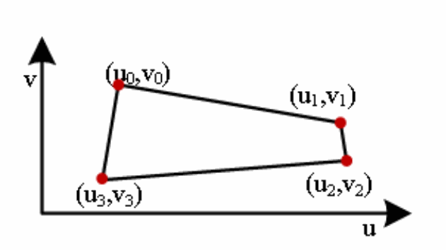
2.2.2.3.6 rk_aiq_awb_uv_range_para_t
【Illustrate】 Defines the UV domain quad white spot area restriction parameters for the Custom AWB algorithm
Technical figure from the English source, PDF p.30.
【Definition】
typedef struct rk_aiq_awb_uv_range_para_s {
    unsigned short pu_region[5];
    unsigned short pv_region[5];
    int slope_inv[4];
} rk_aiq_awb_uv_range_para_t;
【Member】
| Member name |
Description |
|---|---|
| pu_region | The U coordinates of the white dot area of the UV domain form a closed loop, such as [u0, u1,u2, u3, u0], and the value range is [0x0, 0x1ff], with 1 decimal place. |
| pv_region | The V coordinate of the white spot area in the UV domain forms a closed loop, such as [v0, v1, v2, v3, v0], and the value range is [0x0, 0x1ff], with 1 decimal place. |
| slope_inv | The reciprocal slope of the four sides of the white spot region of the UV domain can be taken to 10 decimal places. |
【Note】
Fixed-point or converted parameters based on the AWB/UV domain white points detector section of the Rockchip_Color_Optimization_Guide_ISP30, which are obtained by the calibration tool
For modules, uvDetectionEnable must be configured correctly when it is ture
2.2.2.3.7 rk_aiq_rgb2xy_para_t
【Illustrate】 Define the RGB domain to XY domain conversion parameters for the Custom AWB algorithm.
【Definition】
typedef struct rk_aiq_rgb2xy_para_s {
    unsigned short pseudoLuminanceWeight[3];
    short rotationMat[9];
} rk_aiq_rgb2xy_para_t;
【Member】
| Member name | Description |
|---|---|
| pseudoLuminanceWeight | RGB domain to XY domain conversion parameter: [0, 2^12-1], 12 decimal places. |
| rotationMat | RGB domain to XY domain conversion parameter: [-2^14, 2^14-1], 12 decimal places. |
【Note】
Based on the Rockchip_Color_Optimization_Guide_ISP30 “AWB/RGB2XY” section, the parameters are fixed, and the parameters are obtained by the calibration tool
In relation to the module, when xyDetectionEnable is set to ture, it must be configured correctly
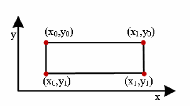
2.2.2.3.8 rk_aiq_awb_xy_range_para_t
【Illustrate】 Defines the XY-domain quadrilateral white spot area restriction parameter for the Custom AWB algorithm.
Technical figure from the English source, PDF p.31.
【Definition】
typedef struct rk_aiq_awb_xy_range_para_s {
    int NorrangeX[2];
    int NorrangeY[2];
    int SperangeX[2];
    int SperangeY[2];
    int SmalrangeX[2];
    int SmalrangeY[2];
} rk_aiq_awb_xy_range_para_t;
【Member】
| Member name |
Description |
|---|---|
| NorrangeX | The horizontal start and end coordinates of the white dot interval in the XY field [x0,x1], the value range: [-2^13, 2^13-1], 10 decimal places. |
| NorrangeY | The vertical start and end coordinates of the white dot interval in the XY field [y0,y1], the value range: [-2^13, 2^13-1], 10 decimal places. |
| SperangeX | The horizontal start and end coordinates of the white dot interval in the XY domain are [x0,x1], and the value range is [-2^13, 2^13-1], with 10 decimal places. |
| SperangeY | The vertical start and end coordinates of the white dot interval in the XY domain are [y0,y1], and the value range is [-2^13, 2^13-1], with 10 decimal places. |
| SmalrangeX | The horizontal start and end coordinates of the white dot interval in the XY field box [x0,x1] are not supported in the current version, and the value range is [-2^13, 2^13-1], with 10 decimal places. |
| SmalrangeY | The vertical start and end coordinates of the white dot interval in the XY field box [y0,y1] are not supported in the current version, and the value range is [-2^13, 2^13-1], with 10 decimal places. |
【Notes】
Based on the fixed-point parameters of the “AWB/XY domain white points detector” section of the Rockchip_Color_Optimization_Guide_ISP30, which are obtained by the calibration tool.
In relation to modules, when xyDetectionEnable is set to ture, it must be configured correctly.
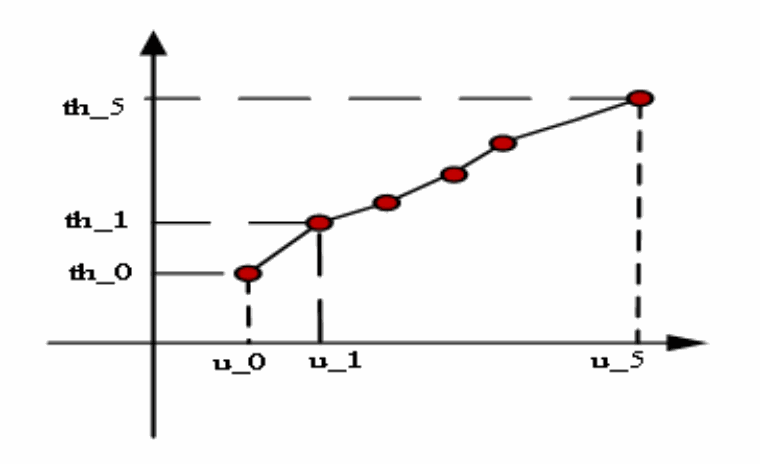
2.2.2.3.9 rk_aiq_awb_rt3dyuv_range_para_t
【Illustrate】 Define the YUV domain white point limit parameter for the Custom AWB algorithm.
【Definition】
typedef struct rk_aiq_awb_rt3dyuv_range_para_s {
    unsigned char thcurve_u[6];
    unsigned short thcure_th[6];
    unsigned short lineP1[3];
    short vP1P2[3];
    unsigned char disP1P2;
} rk_aiq_awb_rt3dyuv_range_para_t;
【Member】
| Member name |
Description |
|---|---|
| thcurve_u | the u-component of the piecewise line u-th; Value range: [0x0, 0xff]; Note: It is necessary to satisfy the power of 2 with the difference between the two adjacent u components. |
| thcure_th | the th component of the piecewise line u-th; Value range: [0x0, 0xfff], 4 decimal places; Note: The piecewise line u-th must be monotonically incremented. |
| lineP1 | Calculate the parameters required for the theoretical white point (y’,u0,v0), the coordinates of the p1 point in the YUV domain; The value range of each component is [0x0, 0xfff], 4 decimal places. |
| vP1P2 | Calculate the parameters required for the theoretical white point (y’, u0, v0), the vector from p1 to p2 in the YUV domain; The value range of each component is [-2^12, 2^12-1], 4 decimal places. |
| disP1P2 | The Euclidean distance between p1 and p2 is 2^disP1P2; Value range: [0,5]. |
【Notes】
Technical figure from the English source, PDF p.33.
Based on the fixed-point or converted parameters of the Rockchip_Color_Optimization_Guide_ISP30 “AWB/YUV domain white points detector” section, which are obtained by the calibration tool.
In relation to the module, when threeDyuvEnable is set to ture and threeDyuvIllu is not set to 7, it must be configured correctly.
2.2.2.3.10 rk_aiq_awb_exc_range_v201_t
【Illustrate】 Define the UV or XY domain white point exclusion/additional region restriction parameters for the Custom AWB algorithm.
【Definition】
typedef struct rk_aiq_awb_exc_range_v201_s {
    rk_aiq_awb_exc_range_domain_t domain;
    bool excludeEnable[RK_AIQ_AWB_XY_TYPE_MAX_V201];
    bool measureEnable;
    int xu[2];
    int yv[2];
} rk_aiq_awb_exc_range_v201_t;
【Member】
| Member name | Description |
|---|---|
| rk_aiq_awb_exc_range_domain_t | Control the exclusion/addition of the white point interval in the XY domain or UV AND selection; Valid values: RK_AIQ_AWB_EXC_RANGE_DOMAIN_UV or RK_AIQ_AWB_EXC_RANGE_DOMAIN_XY, representing the UV and XY domains, respectively. |
| excludeEnable | Exclusion area enable switch; true enabled, false not enabled; Default value: true. |
| measureEnable | Whether the sum of RGain BGain channels in the excluded/additional region is counted; true counts, false doesn’t; Default value: false. |
| xu | Horizontal start and end coordinates of the UV or XY domain white point exclusion/additional area, xu = {x0,x1}; Value range: -2^13, 2^13-1. |
| yv | Vertical start and end coordinates of the UV or XY domain white point exclusion/additional area, yv = {y0,y1}; Value range: -2^13, 2^13-1. |
【Notes】
A maximum of 7 windows can be configured, but only the first 4 measureEnable can be configured to true.
2.3 Develop user AF algorithms
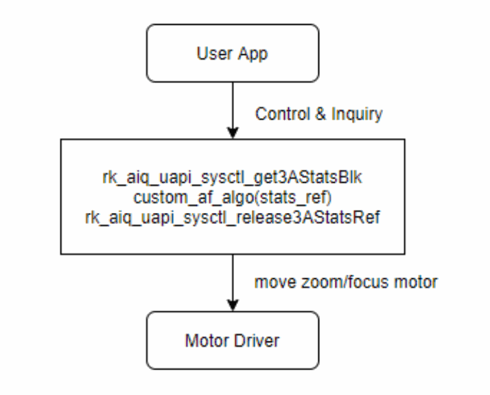
When the user does not use the RK AF algorithm library, the AF algorithm can be developed based on the 3A statistical value to realize functions such as zoom focusing.
When the user implements the AF algorithm,
1. First, call rk_aiq_user_api2_af_SetAttrib to configure AF statistics;
2. Secondly, use the rk_aiq_uapi_sysctl_get3AStatsBlk to obtain 3A statistical values, which is a blocking API, and when a new 3A statistical value is generated, it will be returned immediately;
3. Then the user AF algorithm can perform relevant calculations according to the 3A statistical value, and drive the zoom motor and focus motor to move;
4. Finally, you need to call rk_aiq_uapi_sysctl_release3AStatsRef release the obtained 3A statistical value;
The overall flow of the algorithm is shown in the following figure.
Technical figure from the English source, PDF p.35.
2.3.1 AF statistics module
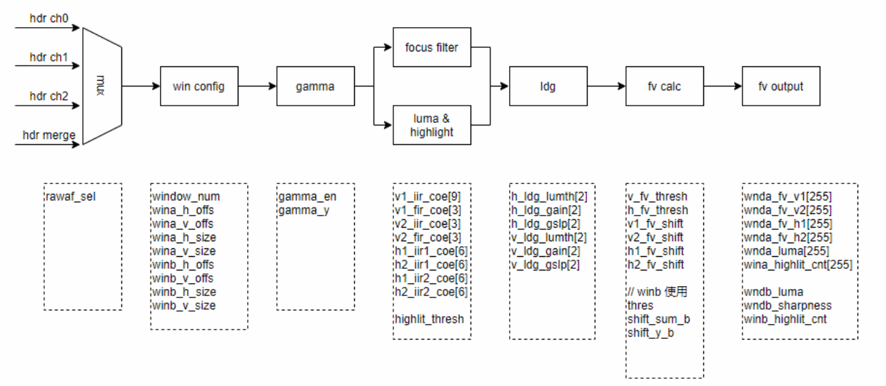
Technical figure from the English source, PDF p.35.
If the sensor inputs an HDR image, the AF module can select the output image of HDR short/medium/long exposure or a data of the HDR composite image as the input data of AF statistics.
If the sensor inputs a Normal image, the AF module can select the input image of the sensor or the debayer image as the input data for AF statistics.
A total of two windows are supported, the main window A and the independent window B.
The main window A contains 15*15 sub-windows, which can be configured with four filters of V1/V2/H1/H2, and output four FV values, brightness values and highlight statistics values of V1/V2/H1/H2.
Independent window B uses a fixed operator to calculate the FV value, and can output an FV value, brightness value, and highlight statistical value.
2.3.2 AF Statistics Window Configuration
Main Window A and Independent Window B support rectangular window configurations. You can configure the coordinates of the upper-left corner of the rectangular window and the width and height of the window.
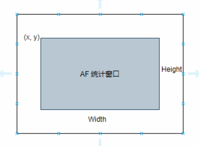
Technical figure from the English source, PDF p.36.
2.3.3 Gamma
Gamma converts the RAW image of the sensor input into the degree to which the human eye perceives natural brightness. The x-coordinate segment is 0 to 1023: 16 16 16 16 32 32 32 32 64 64 64 128 128 128 128 128 The value range of the y coordinate is 0 to 1023.
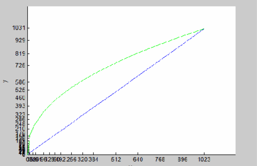
Technical figure from the English source, PDF p.36.
2.3.4 Focus Filter
The main window A provides four filters for V1/V2/H1/H2 to be set, and independent window B uses fixed operators for calculation.
The frequency bands of the V1/V2/H1/H2 filters can be adjusted, and filter register values are generated using filter design tools.
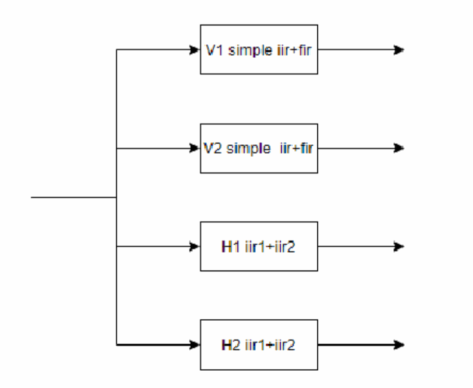
Technical figure from the English source, PDF p.37.
2.3.5 Luma/Highlight
The main window A provides luminance statistics and highlight count statistics.
The FV value is easily affected by the light source, and when the focus is blurred, the low-frequency component in the image increases due to the diffusion of the halo, and the image blur will appear and the FV value will become larger.
The general solution is to use a highlight counter, when the focus is blurred, because the halo expands, the number of high highlights will increase, and when it is clear, the number of high highlights will be the smallest.
2.3.6 Luma Depend Gain
The effect of the light source can also be removed by the LDG function, which attenuates the FV value according to the brightness of the pixel and reduces the FV value at bright spots and too dark points.
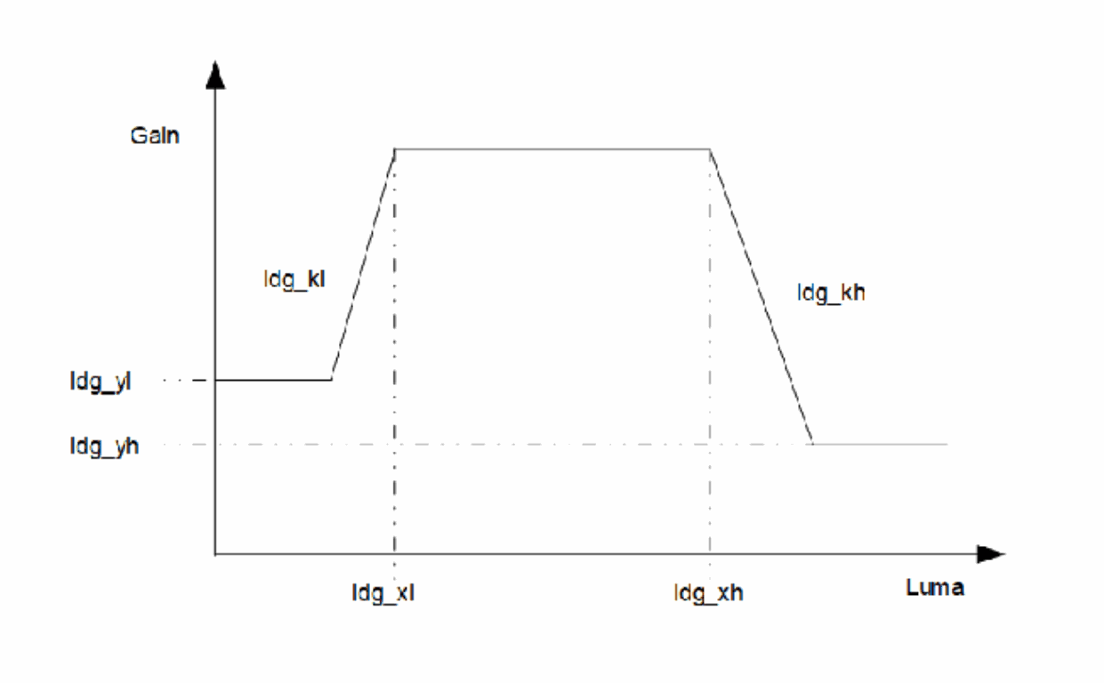
Technical figure from the English source, PDF p.38.
When the brightness value is between [ldg_xl, ldg_xh], the Gain value output is 1, and the FV value is not attenuated;
When the brightness value is between [0, ldg_xl], the Gain value is attenuated according to the slope ldg_kl, and the Gain value is at least ldg_yl;
gain = 256 - ldg_kl*(ldg_xl - x)/256; gain = max(gain, ldg_yl);
When the brightness value is between [ldg_xh, 255], the Gain value is attenuated according to the slope ldg_kh, and the Gain value is at least ldg_yh.
gain = 256 - ldg_kh*(x-ldg_xh)/256; gain = max(gain, ldg_yh);
Horizontal H1/H2 share an LDG curve, vertical V1/V2 share an LDG curve.
2.3.7 Fv threshold
When calculating the Fv value, when the Fv value is less than the Fv threshold information, the final output is not counted, which can reduce the influence of noise.
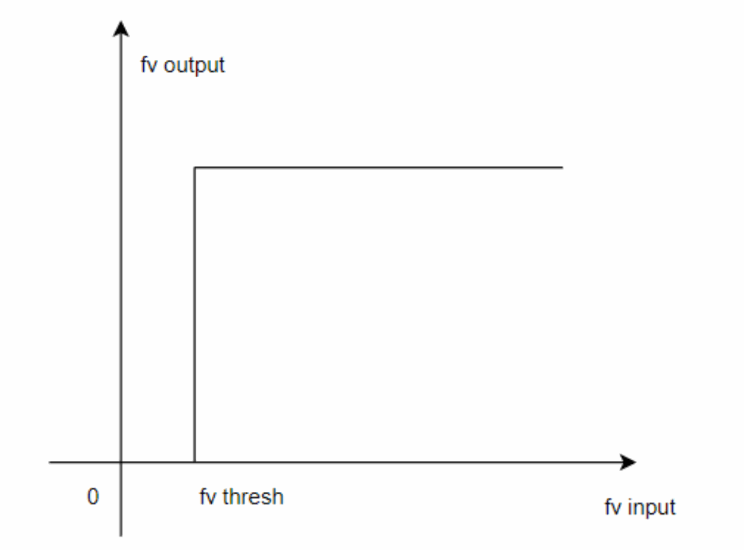
Technical figure from the English source, PDF p.39.
The Fv threshold is the threshold for the LDG output value after the filtered result.
2.3.8 Fv Calc
The Fv value supports absolute value mode and squared mode, and the square mode squares the Fv value, which can increase the proportion of FV value in a clear position.
In order to prevent the last output Fv value from overflowing, you can set four right-shift shift values of v1/v2/h1/h2 in the main window, and two right-shift shift values of fv/luma in the independent window.
2.3.9 Fv Output
The output of main window A contains v1/v2/h1/h2 Fv information for 1515 and luma/highlight information for 1515.
The distribution of the output of the main window A on the image is shown below.
The output of Standalone Window B contains an Fv message, a luminance message, and a highlight statistic.
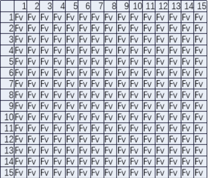
Technical figure from the English source, PDF p.40.
Editable transcription of the source FV grid:
| 1 | 2 | 3 | 4 | 5 | 6 | 7 | 8 | 9 | 10 | 11 | 12 | 13 | 14 | 15 | |
|---|---|---|---|---|---|---|---|---|---|---|---|---|---|---|---|
| 1 | Fv | Fv | Fv | Fv | Fv | Fv | Fv | Fv | Fv | Fv | Fv | Fv | Fv | Fv | Fv |
| 2 | Fv | Fv | Fv | Fv | Fv | Fv | Fv | Fv | Fv | Fv | Fv | Fv | Fv | Fv | Fv |
| 3 | Fv | Fv | Fv | Fv | Fv | Fv | Fv | Fv | Fv | Fv | Fv | Fv | Fv | Fv | Fv |
| 4 | Fv | Fv | Fv | Fv | Fv | Fv | Fv | Fv | Fv | Fv | Fv | Fv | Fv | Fv | Fv |
| 5 | Fv | Fv | Fv | Fv | Fv | Fv | Fv | Fv | Fv | Fv | Fv | Fv | Fv | Fv | Fv |
| 6 | Fv | Fv | Fv | Fv | Fv | Fv | Fv | Fv | Fv | Fv | Fv | Fv | Fv | Fv | Fv |
| 7 | Fv | Fv | Fv | Fv | Fv | Fv | Fv | Fv | Fv | Fv | Fv | Fv | Fv | Fv | Fv |
| 8 | Fv | Fv | Fv | Fv | Fv | Fv | Fv | Fv | Fv | Fv | Fv | Fv | Fv | Fv | Fv |
| 9 | Fv | Fv | Fv | Fv | Fv | Fv | Fv | Fv | Fv | Fv | Fv | Fv | Fv | Fv | Fv |
| 10 | Fv | Fv | Fv | Fv | Fv | Fv | Fv | Fv | Fv | Fv | Fv | Fv | Fv | Fv | Fv |
| 11 | Fv | Fv | Fv | Fv | Fv | Fv | Fv | Fv | Fv | Fv | Fv | Fv | Fv | Fv | Fv |
| 12 | Fv | Fv | Fv | Fv | Fv | Fv | Fv | Fv | Fv | Fv | Fv | Fv | Fv | Fv | Fv |
| 13 | Fv | Fv | Fv | Fv | Fv | Fv | Fv | Fv | Fv | Fv | Fv | Fv | Fv | Fv | Fv |
| 14 | Fv | Fv | Fv | Fv | Fv | Fv | Fv | Fv | Fv | Fv | Fv | Fv | Fv | Fv | Fv |
| 15 | Fv | Fv | Fv | Fv | Fv | Fv | Fv | Fv | Fv | Fv | Fv | Fv | Fv | Fv | Fv |
2.3.10 Calculation of the final FV value
H1 and V1 can be configured in the low-pass band for coarse search and H2 and V2 in the high-pass band for fine search.
The horizontal filter output H and the vertical filter output V can be weighted with certain weights.
FV = FvH * weight + FvV * (1-weight)
The FV values obtained from each block can also be weighted according to a certain weight as needed.
2.3.11 Configuration of AF statistics
Use rk_aiq_user_api2_af_SetAttrib for configuration
XCamReturn
rk_aiq_user_api2_af_SetAttrib(const rk_aiq_sys_ctx_t* sys_ctx, rk_aiq_af_attrib_t
attr);
| Parameter Name | Description | Input/Output |
|---|---|---|
| sys_ctx | AIQ context pointer | Input |
| attr | Parameter properties of focus | Input |
The rk_aiq_af_algo_meas_v30_t in the parameter rk_aiq_af_attrib_t are described as follows:
typedef struct {
    unsigned char af_en;
    unsigned char rawaf_sel;
    unsigned char gamma_en;
    unsigned char gaus_en;
    unsigned char v1_fir_sel;
    unsigned char hiir_en;
    unsigned char viir_en;
unsigned char v1_fv_outmode; // 0 square, 1 absolute
unsigned char v2_fv_outmode; // 0 square, 1 absolute
unsigned char h1_fv_outmode; // 0 square, 1 absolute
unsigned char h2_fv_outmode; // 0 square, 1 absolute
unsigned char ldg_en;
unsigned char accu_8bit_mode; // fix to 1
unsigned char ae_mode;
unsigned char y_mode; // fix to 0
unsigned char line_en[RKAIQ_RAWAF_LINE_NUM];
unsigned char line_num[RKAIQ_RAWAF_LINE_NUM];
unsigned char window_num;
unsigned short wina_h_offs;
unsigned short wina_v_offs;
unsigned short wina_h_size;
unsigned short wina_v_size;
unsigned short winb_h_offs;
unsigned short winb_v_offs;
unsigned short winb_h_size;
unsigned short winb_v_size;
unsigned short gamma_y[RKAIQ_RAWAF_GAMMA_NUM];
// [old version param]
unsigned short thres;
unsigned char shift_sum_a;
unsigned char shift_sum_b;
unsigned char shift_y_a;
unsigned char shift_y_b;
/**********[Vertical IIR (v1 & v2)]************/
short v1_iir_coe[9];
short v1_fir_coe[3];
short v2_iir_coe[3];
short v2_fir_coe[3];
/**********[Horizontal IIR (h1 & h2)]************/
short h1_iir1_coe[6];
short h2_iir1_coe[6];
short h1_iir2_coe[6];
short h2_iir2_coe[6];
/**********[Focus value statistic param]**********/
// level depended gain
// input8 lumi, output8bit gain
unsigned char h_ldg_lumth[2]; //luminance thresh
unsigned char h_ldg_gain[2]; //gain for [minLum,maxLum]
unsigned short h_ldg_gslp[2]; //[slope_low,-slope_high]
unsigned char v_ldg_lumth[2];
unsigned char v_ldg_gain[2];
unsigned short v_ldg_gslp[2];
// coring
unsigned short v_fv_thresh;
unsigned short h_fv_thresh;
    // left shift, more needed if outmode=square
    unsigned char v1_fv_shift; //only for sel1
    unsigned char v2_fv_shift;
    unsigned char h1_fv_shift;
    unsigned char h2_fv_shift;
    /**********[High light]**********/
    unsigned short highlit_thresh;
} rk_aiq_af_algo_meas_v30_t;
| Member Name | Description |
|---|---|
| af_en | Whether AF is enabled Information statistics, 0 is off and 1 is on |
| rawaf_sel | Select the channel of AF information statistics, the value range is 0-3, the long/medium/short/synthetic frame channel selection corresponding to HDR mode, the general AF selection medium frame channel, the non-HDR mode is set to 0, and the HDR mode is set to 1 |
| gamma_en | The gamma module enables the switch, 0 is off and 1 is on |
| gaus_en | The setting needs to be fixed to 1 |
| v1_fir_sel | The setting needs to be fixed to 1 |
| hiir_en | H1/H2 channel enable switch, 0 is off and 1 is on |
| viir_en | V1/V2 channel enable switch, 0 is off and 1 is on. Note that when the gamma_en is open, the viir_en must be set to 1 |
| v1_fv_outmode | V1 channel FV output mode selection, 0 for squared mode, 1 for absolute value mode |
| v2_fv_outmode | V2 channel FV output mode selection, 0 for squared mode, 1 for absolute mode |
| h1_fv_outmode | H1 channel FV output mode selection, 0 for squared mode, 1 for absolute mode |
| h2_fv_outmode | H2 channel FV output mode selection, 0 for squared mode, 1 for absolute mode |
| ldg_en | The LDG function enables the switch, 0 is off and 1 is on |
| accu_8bit_mode | The setting needs to be fixed to 1 |
| ae_mode | When the ae_mode is set to 1, RAWAF enables 15x15 luminance averaging statistics, multiplexing the logic of the RAWAE_BIG module |
| y_mode | The setting needs to be fixed to 0 |
| line_en | It is not yet in effect |
| line_num | It is not yet in effect |
| window_num | The number of windows in effect, when the window_num is 1, WinA (main window) takes effect; When the window_num is 2, WinA (main window) and WinB (independent window) take effect |
| wina_h_offs | The horizontal coordinate of the first pixel in the upper-left corner of Wina (main window), which must be greater than or equal to 2 |
| wina_v_offs | The vertical coordinate of the first pixel in the upper-left corner of WinA (main window), which must be greater than or equal to 1 |
| wina_h_size | the window width of Wina (main window), which must be less than the image width -2-wina_h_offs; At the same time, the value must be a multiple of 15; |
| wina_v_size | the window width of Wina (main window), which must be less than the image width -2-wina_v_offs; At the same time, the value must be a multiple of 15; |
| winb_h_offs | The horizontal coordinate of the first pixel in the upper-left corner of Winb (Standalone Window), which must be greater than or equal to 2 |
| winb_v_offs | The vertical coordinate of the first pixel in the upper-left corner of Winb (Standalone Window), which must be greater than or equal to 1 |
| winb_h_size | The window width of winb (independent window), which must be less than the image width -2-wina_h_offs |
| winb_v_size | The window height of WinB (Independent Window), which must be less than the image height -2-wina_v_offs |
| gamma_y | The y value of the gamma table, the value range is 0-1023; The x-coordinate segment is 0 to 1023: 16 16 16 16 32 32 32 32 64 64 64 128 128 128 128 128 |
| thres | When the calculated fv value is less than this value, the fv value is changed to 0 to reduce the influence of noise, and the value range is 0-0xFFFF |
| shift_sum_a | It is currently unavailable and can be fixed to 0 |
| shift_sum_b | The shit bit value of the fv value of win b (independent window) will shift the fv value to the right according to this value to avoid the overflow of the obtained fv value, and the value range is 0-7 |
| shift_y_a | It is currently unavailable and can be fixed to 0 |
| shift_y_b | The shit bit value of the luma value of win b (independent window) will shift the luma value to the right according to this value to avoid the overflow of the luma value, and the value range is 0-7 |
| v1_iir_coe[9] | The 3X3 IIR factor for the V1 channel is set according to the output of the AF filter coefficient generation tool |
| v1_fir_coe[3] | The 1x3 FIR factor for the V1 channel is set to the output of the AF filter coefficient generation tool |
| v2_iir_coe[3] | The 1x3 IIR factor for the V2 channel is set according to the output of the AF filter coefficient generation tool |
| v2_fir_coe[3] | The 1x3 FIR factor for the V2 channel is set according to the output of the AF filter coefficient generation tool |
| h1_iir1_coe[6] | The 1X6 IIR1 coefficient for the H1 channel is set according to the output of the AF Filter Factor Generation tool |
| h2_iir1_coe[6] | The 1X6 IIR1 coefficient for the H2 channel is set according to the output of the AF filter coefficient generation tool |
| h1_iir2_coe[6] | The 1X6 IIR2 coefficient for the H1 channel is set according to the output of the AF filter coefficient generation tool |
| h2_iir2_coe[6] | The 1X6 IIR2 coefficient for the H2 channel is set according to the output of the AF filter coefficient generation tool |
| h_ldg_lumth[2] | The brightness threshold coefficient of the ldg module used for H1/H2 channels, 0 is set for the left dark area, 1 is the right highlight area, and the value range is 0~255 |
| h_ldg_gain[2] | The minimum gain value of the ldg module used for H1/H2 channels, 0 is the left dark area setting, 1 is the right highlight area setting, the value range is 0~255 |
| h_ldg_gslp[2] | The slope coefficient of the ldg module used for H1/H2 channels, 0 is set for the left dark area, 1 is set for the right highlight area, and the value range is 0~65535 |
| v_ldg_lumth[2] | The brightness threshold coefficient of the ldg module used for V1/V2 channels, 0 is set for the left dark area, 1 is the right highlight area, and the value range is 0~255 |
| v_ldg_gain[2] | The minimum gain value of the ldg module used for V1/V2 channels, 0 is the left dark area setting, 1 is the right highlight area setting, the value range is 0~255 |
| v_ldg_gslp[2] | The minimum gain value of the ldg module used for V1/V2 channels, 0 is the left dark area setting, 1 is the right highlight area setting, the value range is 0~255 |
| v_fv_thresh | For the AF statistical threshold used for V1/V2 channels, when the calculated fv value is less than this value, the fv value is changed to 0, which can reduce the influence of noise, and the value range is 0-0x0FFF |
| h_fv_thresh | For the AF statistical threshold used for H1/H2 channels, when the calculated fv value is less than this value, the fv value is changed to 0, which can reduce the influence of noise, and the value range is 0-0x0FFF |
| v1_fv_shift | The shit bit value of the fv value used for the V1 channel will shift the fv value to the right according to this value to avoid the overflow of the obtained fv value, and the value range is 0-7 |
| v2_fv_shift | The shit bit value of the fv value used for the V2 channel will shift the fv value to the right according to this value to avoid the overflow of the obtained fv value, and the value range is 0-7 |
| h1_fv_shift | The shit bit value of the fv value used for the H1 channel will shift the fv value to the right according to this value to avoid the overflow of the obtained fv value, and the value range is 0-7 |
| h2_fv_shift | The shit bit value of the fv value used for the H2 channel will shift the fv value to the right according to this value to avoid the overflow of the obtained fv value, and the value range is 0-7 |
| highlit_thresh | Indicates the threshold of the highlight statistics, when higher than this value, it is considered to be high highlights, included in the statistics, only the number of high highlights in each area is accumulated, and the value range is 0-0x0FFF |
2.3.12 Acquisition of AF statistical values
See the “Statistics” section of Rockchip_Development_Guide_ISP30 for details
rk_aiq_uapi_sysctl_get3AStatsBlk () / rk_aiq_uapi_sysctl_release3AStatsRef()
The relevant structure for AF statistical results is rk_aiq_af_algo_stat_v30_t
2.3.13 Use of filter design tools
Please refer to the Filter Design Tool documentation.
2.4 Refer to the code sample
For customer 3A algorithm implementation reference code examples, you can refer to:
Directory: AIQ root/rkisp_demo/demo/
|——-ae_algo_demo // AE algorithm reference code
|——-awb_algo_demo // AWB algorithm reference code
|——-af_algo_demo // AF algorithm reference code