
This article fully preserves the technical body (PDF pp.9–47) of the 47-page English V1.0.34 source. No corresponding Chinese PDF was supplied. Chinese and Russian fully translate the English source; all three articles use original English-PDF figures, including Chinese labels already present in those originals. Code, parameters, identifiers, example values and code comments retain the source text; prose and captions are localized.
The source chipset scope is reproduced below. It specifies neither a single kernel version nor particular ArmSoM boards. This is an ArmSoM platform reference: verify the actual SoC, module, sensor, VCM/OIS, ISP, SDK/BSP, calibration DLL/API version, drivers and OTP/EEPROM layout. Source module examples are not ArmSoM test results. No hardware validation, calibration, programming or camera operation was performed.
Operational risk and source caveats: OTP/EEPROM programming may be irreversible or overwrite module calibration. Verify the manufacturer workflow and target storage layout first. Several source defaults, function declarations and appendix calls differ. The appendix is a source example, not a guarantee of compilability or production suitability. Formulas, addresses, bit widths and IDs retain the source values; technical constants were not silently corrected.
| Source chipset scope |
|---|
| RV1109 / RV1126 / RK356X / RK3588 |
Source caveats and verification record: EDITORIAL-NOTES. ArmSoM · Rockchip Linux
1 LSC&AWB Calibration process
1.1 Calibration scheme
1. Light source environment and equipment
D50 (5000K±100K) to avoid stray light interference from other environments.
Homogenizer or DNP light box that satisfies the above light source, the homogenizer is shown in the following figure:
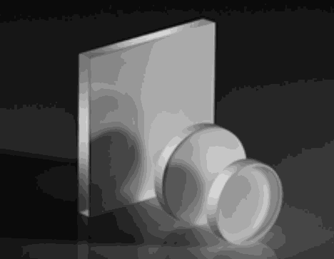
Technical figure from the English source, PDF p.9.
2. How to shoot
1. According to the actual situation, you can choose one of the following two methods
- Use a homogenizer: Place the coated side of the homogenizer facing the lens close to the horizontal, keeping the end face of the module, the homogenizer, and the light source panel parallel.
- Use DNP light box: Place the module 1-2cm in front of the DNP light source panel, keeping the end face of the module parallel to the light source panel.
- Disable functions such as mirror/flip
- Select the exposure value so that the maximum brightness (8bit) of the G channel of the image reaches between 160~180
- Use that exposure to take a raw image and save it
3. AWB calibration
1. Select the center area of the Raw image (20% of the length and width of each channel) and calculate the mean values of R, Gr, Gb, and B channels
Gr_ave=Gr average of ROI - Black level
Gb_ave=Gb average of ROI - Black level
R_ave = Red average of ROI - Black level
B_ave = Blue average of ROI - Black level
2. Calculate R/Gb and B/Gb and Gr/Gb
R/Gb=R_ave/Gb_ave
B/Gb=B_ave/Gb_ave
Gr/Gb=Gr_ave/Gb_ave
3. Fixed-point R/Gb, B/Gb, and Gr/Gb to 10 bitsR/Gb_hex=R/Gb * 1024
B/Gb_hex=B/Gb * 1024
Gr/Gb_hex=Gr/Gb * 1024
4. LSC calibration
1. Set the target value for the calibration calculation to 70%
2. Calculate the gain of each of the four channels to 10 bits
1.2 Control schemes
1. Before LSC calibration
1. Y shading standard :
ROI = 1/5 Width * 1/5Height
YShading_Corner = Y_Corner/Y_Center
30% < YShading_Corner < 55%
Ydiffer = YShading_Corner_Max - YShading_Corner_Min < 7%
2. Color Shading standard:
Color shading uniformity of a single module (control the difference between each block and the central block of a single module)
ROI frame: 1/5*1/5 Calculate the difference between the 24 blocks and the central block
ROI = 1/5Width * 1/5Height
|(R/G_Corner)/(R/G_Center)-1| < 15%
|(B/G_Corner)/(B/G_Center)-1| < 15%
2. LSC calibration
For the problem of asymmetry of vignetting around the captured RAW data due to module placement problems, the ratio parameter card control calibration result is added lsc_otp_Calibrate interface (default ratio=1.5);
If the optical center shifts due to the assembly of the module itself, the ratio can be increased to increase the pass rate.
3. After LSC calibration
1. Y shading standard :
ROI = 1/5 Width * 1/5Height
YShading_Corner = Y_Corner/Y_Center
Ydiffer = YShading_Corner_Max - YShading_Corner_Min < 5%
2. Color Shading standard:
Color shading uniformity of a single module (control the difference between each block and the central block of a single module)
ROI frame: 1/5*1/5 Calculate the difference between the 24 blocks and the central block
ROI = 1/5Width * 1/5Height
|(R/G_Corner)/(R/G_Center)-1| < 5%
|(B/G_Corner)/(B/G_Center)-1| < 5%
2 PDAF Calibration Process
PDAF calibration is divided into two parts: Gain Map calibration and DCC Map calibration, and the calibration process is as follows:
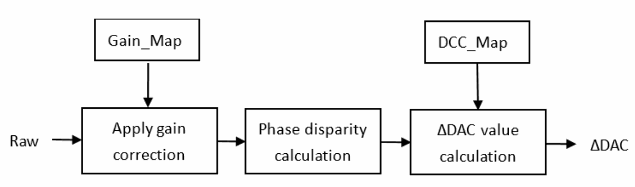
Technical figure from the English source, PDF p.12.
2.1 Preparation before calibration
1. Module preparation
(1) Lens dirt detection
(2) VCM detection: test linearity, lens position accuracy and stability
(3) AF basic correction:
To determine the relationship between DAC and focus distance—– calibrate the position of the motor of the module lens at the focus Inf and Marco, record the corresponding DAC_inf and Dac_marco values, determine the DCC_LENS_BEGIN and DCC_LENS_END, and the corresponding object distance when the focus is clearest in the center position of the motor is DCC Map calibration distance a.
The center position of the motor DAC = (DAC_INF + DAC_MACRO)/2, and the corresponding calibration distance a can be determined by querying the Lens depth of field table. First, determine the lens shift of INF and MACRO in the lens depth of field table, calculate the middle distance between the two, and find the lens shift closest to the middle distance from the depth of field table, that is, the center position of the motor and the corresponding object distance A. For example, when the object distance is infinite, the corresponding lens shift is 0, and the nearest object distance is selected as 10cm, and the corresponding lens shift is -0.183, then the lens shift in the center position of the motor is -0.0915, which is the closest to -0.091, and the corresponding DCC Map calibrated object distance a is 0.20 meters.
| Object Distance (m) | Lens Shift (mm) | Far Field (m) | Near Field (m) |
|---|---|---|---|
| INF | 0.000 | - | - |
| 10.0 | -0.002 | INF | 4.33 |
| 7.6 | -0.002 | 14417.449 | 3.81 |
| 5.0 | -0.004 | 14.511 | 3.02 |
| 4.0 | -0.004 | 8.406 | 2.63 |
| 3.0 | -0.006 | 4.941 | 2.15 |
| 2.0 | -0.009 | 2.71 | 1.59 |
| 1.9 | -0.009 | 2.53 | 1.52 |
| 1.8 | -0.010 | 2.35 | 1.46 |
| 1.7 | -0.010 | 2.19 | 1.39 |
| 1.6 | -0.011 | 2.02 | 1.32 |
| 1.5 | -0.012 | 1.87 | 1.25 |
| 1.4 | -0.013 | 1.71 | 1.18 |
| 1.3 | -0.014 | 1.57 | 1.11 |
| 1.2 | -0.015 | 1.42 | 1.04 |
| 1.1 | -0.016 | 1.28 | 0.96 |
| 1.0 | -0.018 | 1.15 | 0.88 |
| 0.9 | -0.020 | 1.02 | 0.81 |
| 0.8 | -0.022 | 0.89 | 0.72 |
| 0.7 | -0.025 | 0.77 | 0.64 |
| 0.6 | -0.029 | 0.65 | 0.56 |
| 0.5 | -0.035 | 0.53 | 0.47 |
| 0.45 | -0.039 | 0.478 | 0.425 |
| 0.40 | -0.044 | 0.422 | 0.380 |
| 0.35 | -0.051 | 0.366 | 0.335 |
| 0.30 | -0.059 | 0.312 | 0.289 |
| 0.25 | -0.071 | 0.258 | 0.242 |
| 0.20 | -0.091 | 0.202 | 0.192 |
| 0.15 | -0.120 | 0.153 | 0.147 |
| 0.14 | -0.129 | 0.142 | 0.138 |
| 0.13 | -0.140 | 0.132 | 0.128 |
| 0.12 | -0.152 | 0.122 | 0.118 |
| 0.11 | -0.166 | 0.111 | 0.109 |
| 0.10 | -0.183 | 0.101 | 0.099 |
| 0.09 | -0.205 | 0.091 | 0.089 |
| 0.08 | -0.232 | 0.081 | 0.079 |
| 0.07 | -0.267 | 0.071 | 0.069 |
| 0.06 | -0.315 | 0.060 | 0.060 |
| 0.05 | -0.383 | 0.050 | 0.050 |
| Item | Detail | Note |
|---|---|---|
| Test Chart | Vendor Definition | It is recommended that checkerboards, diamond- charts, etc. have test charts with high contrast and moderate frequency |
| Test the brightness of surface lighting |
More than 400Lux | Imaging should not flicker |
| The distance between the module and the test chart |
INF:2~5m Marco:10-20cm (refer to the depth of field table for details) |
The INF distance simulates the telephoto position using a teleconverter |
| The module corrects the direction |
When INF/MACRO is corrected, the optical axis of the module is horizontal |
In the case of open loop VCM, only the horizontal direction is corrected, and in the case of closed loop VCM, the optical axis can be corrected upward, note that the Inf/Macro correction direction is the same |
| Gain settings | Same as AWB | The digital gain is fixed at 1, and the analog gain (traditional PD or 2x1OCL, again set to 1x; Dual-photodiode’s PD, again set to 2x) |
| Sensor Settings | Disable settings such as mirror/flip/OB/dead pixel removal in the sensor |
|
| Image brightness requirements |
Same as AWB | When displayed at full size, the average brightness value of the TOP 10% G channel in the ROI area of 1/32W*1/32H in the center of the screen is 800LSB (raw10), and the average value of the dual pd G channel is 700LSB (raw10) |
| Number of samples for error testing |
Range inspection: each module should be accurately inspected: greater than 10pcs |
If the test fails, the correction method needs to be modified to make the AF far and near focus correction results more accurate |
(4) If the module is OIS-enabled, the camera shake correction needs to be completed before calibrating the lsc and pdaf. Move the motor to the reference XY position to verify that the OIS is configured. This step will generate flat field images for LSC and PDAF indexing;
(5) Complete the black level and LSC correction, and if necessary, the field curvature can be corrected
2、Module AE settings
(1) Module AE setting: the digital gain is fixed to 1; Analog gain (traditional PD or 2x1OCL, again set to 1x; Dual-photodiode’s PD and again are set to 2x to prevent pixel blooming)
(2) Exposure time: In order to prevent the charge blooming phenomenon of dual-pd and the overexposure of normal pixels (regular_pixel=dual_pd_l+dual_pd_r), adjust the exposure time to make the brightness of the G channel in the center area 700 (raw10) when displaying the full size; For OCL and metal-shield types, a G- channel brightness of 800 (raw10) is guaranteed in the center area. The sensor recommends that the exposure time be set to an integer multiple of 10ms to avoid power frequency interference.
2.2 Gain Map calibration
1、Light source environment and equipment
D50 (5000K±100K) to avoid stray light interference in other environments;
Homogenizer or DNP light box that meets the above light source, integrating sphere;
2、Shooting method
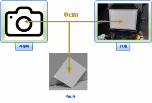
Technical figure from the English source, PDF p.16.
- Place the module in front of the uniform surface light source, keep the end face of the module parallel to the light source surface (eg. the integrating sphere used in the experiment, the panel brightness value is adjusted to 6.6), and the homogenizer is placed at the front end of the lens to make the surface light source fill the picture;
- Sensor’s gain - for metal-shield and 2x1OCL type sensors, set again and dgain to 1x, dual-pd type sensors, again set to 2x, dgain set to 1x, and exposure time set to multiples of 10;
- Turn off settings such as mirro/flip/OB in the sensor
- The average brightness value of the TOP 10% G channel in the ROI area of 1/32W*1/32H in the center of the screen is 800LSB (raw10) or 200LSB (raw8) when displayed in full size. The mean value of the dual pd G channel is 700LSB (raw10) or 175LSB (raw8);
- Turn on the camera to warm up for 3 minutes, move the motor to the center position to shoot 3 RAW images in a row, first check whether the number of dead pixels exceeds the allowable range, if the number of dead pixels exceeds the allowable range, you need to reduce the brightness of the picture and shoot again; If the dead pixel detection passes, the average image data is obtained;
3、Calibration
Calling pdaf_gainmap_calibration (…) The function generates the gainmap data and obtains the size of the gainmap, which is gainmap_width*gainmap_height *2 bytes (including left gainmap and right gainmap).
4、Verification
1. Ensure that the environment in step 2 is the same, take a test image, and input the calibrated gainmap and test image into the function pdaf_gainmap_vertification (…), if the return is 1, the verification is successful, and the calibrated gainmap is available; If the return value is -1, it indicates whether the number of dead pixels exceeds the allowable range, and you need to reduce the brightness of the image and reshoot.
2. Validation criteria
If the difference between the left PD pixel and the right PD pixel corrected by gainmap is less than 5%, the verification is successful.
2.3 DCC Map calibration
DCC (defocus conversion coefficient) represents the relationship between the motor position and the left and right image differences, divides the image into different regions, moves the motor in equal steps, calculates the pd value at different positions, and uses linear regression to obtain the DCC value of different regions —DCCMAP

DCC = Δlensposition[dac]/Δphasedisparity[pixel]
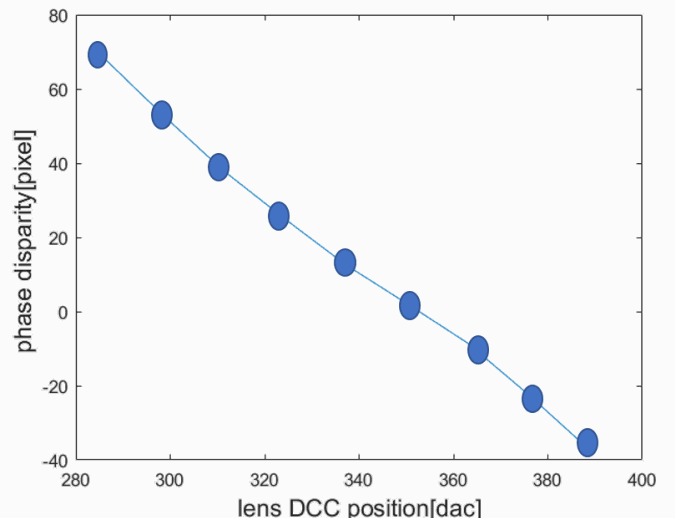
Technical figure from the English source, PDF p.17.
[optional]
For some modules, the PD_OFFSET needs to be calibrated. For example, when the motor is DAC_0, a blurred focus plot is obtained, and the calculated clear focus DAC = DAC_0 + PD * DCC + PD_OFFSET * DCC
1、Light source environment and equipment
D50 (5000K±100K) to avoid stray light interference from other environments.
Homogeneous sheet or DNP light box that meets the above light source, integrating sphere, black and white standard plate;
Standard plate: The standard plate is made of customized translucent film sheet, and the pattern is evenly spaced black and white stripes or diamond-shaped grids.
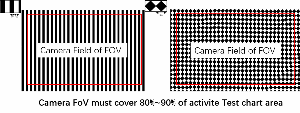
Technical figure from the English source, PDF p.17.
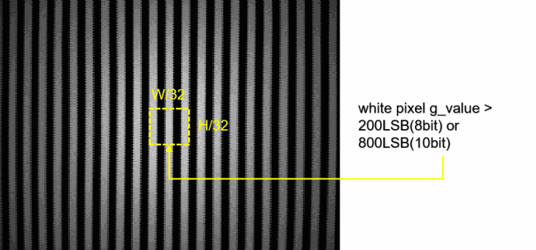
Technical figure from the English source, PDF p.18.
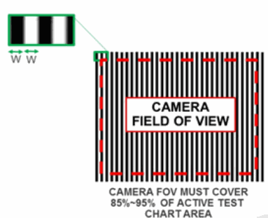
Technical figure from the English source, PDF p.18.
The calibration distance a is determined in the 2.1.1 AF base correction step
The width of the standard depends on the horizontal FOV of the lens and the calibration distance a, which is recommended

S >= a * tan(FOV * pi/360) * 2/0.9
The calibration distance is determined in the 2.1.1 AF base correction step
The width of the standard depends on the horizontal FOV of the lens and the calibration distance a, which is recommended

λ[mm] = (u[um]/1000) * raw_width/(6 * dccmap_width)

W[mm] = (a[mm] - f[mm])/f[mm] * λ[mm]
For IMX258, the coefficient λ is recommended to be 0.11, and for S5KJN1, the coefficient λ is recommended to be 0.088~0.099.
DCC calibration requires correct customization and placement of the standard board, and the inappropriate size of the stripes, rotation or deformation during placement, and over-dimming or overexposure of the brightness will lead to the failure of DCC calibration, as shown in the figure below for some error cases.
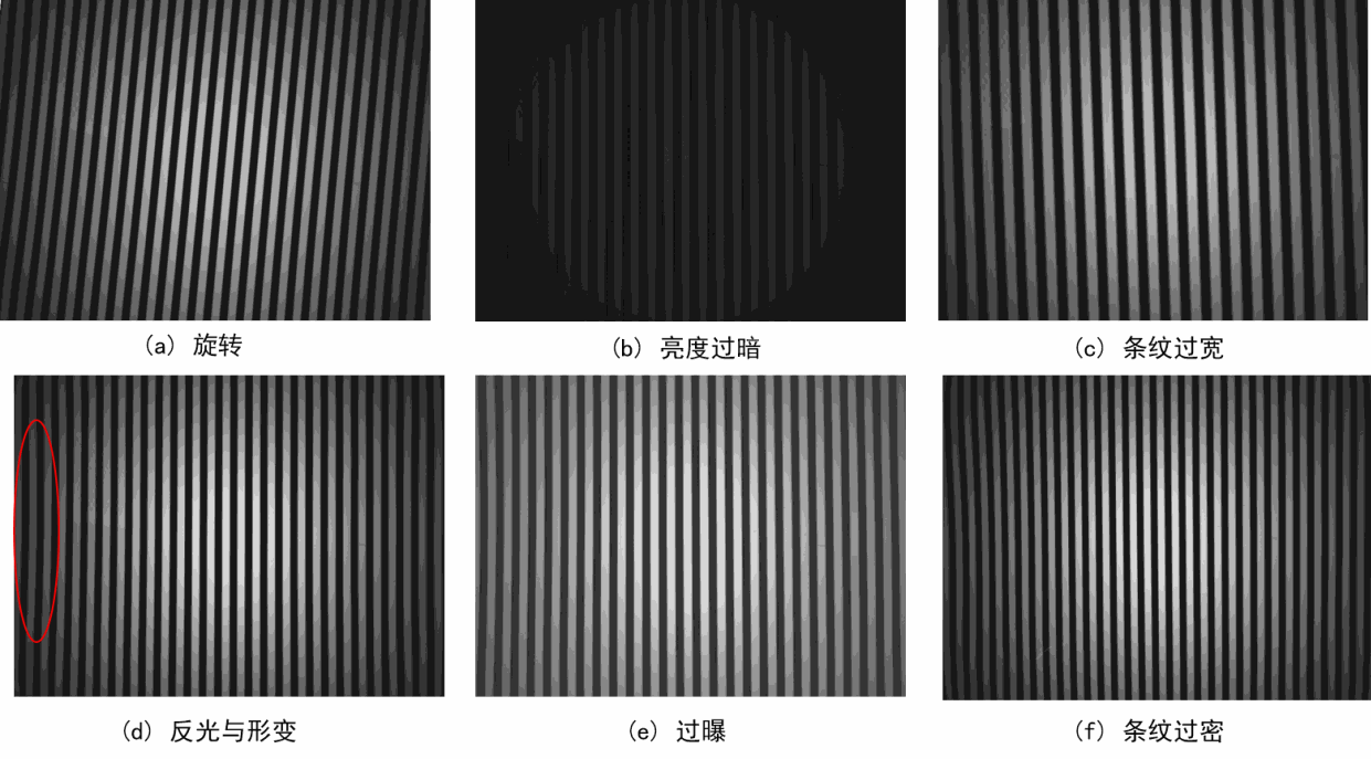
Technical figure from the English source, PDF p.18.
2、How to shoot
- Place the striped film in front of the integrating sphere, and place the module in front of the standard plate about the middle of the focus, and the distance value is determined by the basic correction in step 2.1.1AF. The end face is kept parallel to the standard plate to avoid rotation, tilt and twisting of the standard plate, and to ensure that the standard plate is full of images when shooting;
- sensor gain: for metal-shield and 2x1OCL sensors, set again and dgain to 1x, dual-pd sensor, again set to 2x, and dgain set to 1x;
- Turn off the settings of mirro/flip/OB/dead pixel removal in the sensor;
- Exposure: Ensure that the average value of the white block g channel in the ROI area of 1/32w*1/32h in the center of the standard plate screen is 800LSB (raw10) and 200LSB (raw8), and the average value of the dual pd G channel is 700LSB (raw10) or 175LSB (raw8), so as to avoid insufficient brightness or overexposure affecting the DCC calibration accuracy; For metal-shield sensors, ensure that the non-shielded pixels are not overexposed.
- Move the motor from DCC_LENS_BEGIN to DCC_LENS_END at DCC_LENS_INTERVAL sampling intervals, and take three RAW images after the motor stabilizes each time to obtain the average image data of each position (eg. During the experiment, the code was moved from 0 to 64 at 8 intervals, and a total of 9 positions were taken, and 27 images were taken
3、Demarcate
Enter the gainmap, motor position parameters, and average image data for each position calibrated in Section 2.1 into the function pdaf_dccmap_calibration (…) to obtain the dccmap data and obtain the size of the dccmap,
the size is dccmap _width*dccmap _height *2 bytes (if the calibration PD_OFFSET is selected, the value size is 2bytes at the same time DCC_RSQ_THRESHOLD); If the number of blocks that do not meet the linearity threshold is greater than a certain number, the calibration fails, and you need to check whether the input data is incorrect, adjust the calibration environment and shoot again.
4、Verify
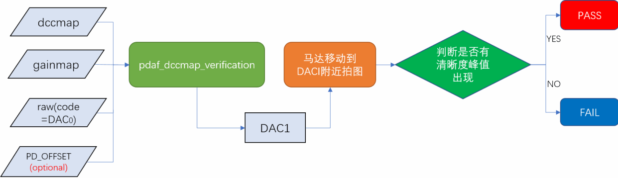
The purpose of this step is to verify that the current calibrated dccmap is correct The verification process is shown in the following figure:
Technical figure from the English source, PDF p.19.
1. The lighting environment of the verification data shooting is the same as that of the DCCmap calibration environment, and the lens surface is parallel to the standard plate to ensure that the image is filled with the standard plate pattern during shooting.
2. Turn on the camera to warm up for 3 minutes, and adjust the motor to a image blur position DAC0,

DAC0 ∈ (DACinf + 0.2 * abs(DACinf - DACmacro), DACinf + 0.8 * abs(DACinf - DACmacro)]
After the motor is stabilized, three Raw images are captured, the average image data is obtained, and the current position information of the motor DAC0, the average image data, and the calibrated gainmap and dccmap are input into the pdaf_dccmap_vertification() function, and the ideal focusing position DAC1 of the image at the focus blur is calculated;
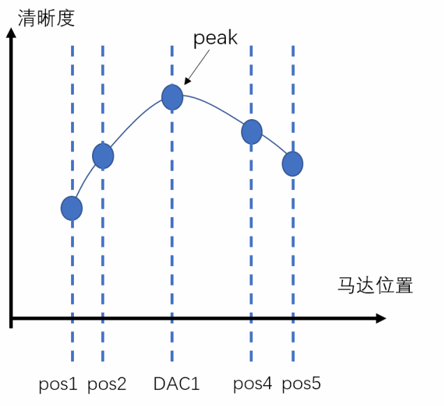
3. Then move the motor to DAC1, and capture five images in tolerance_factor*abs(DACinf-DACmacro)+Δ (e.g.Δ=2) before and after DAC1, tolerance_factor the tolerance range during verification, and the error range is different for different types of sensors (e.g.5%, 10%, 20%).
Move the motor from position 1 to position 5 during verification, and the five positions are (e.g.tolerance_factor=10%, Δ=2)
4.
| Index | Position |
|---|---|
| 1 | DAC1-10% *abs(DACinf-DACmacro)-Δ |
| 2 | DAC1-10% *abs(DACinf-DACmacro) |
| 3 | DAC1 |
| 4 | DAC1+10% *abs(DACinf-DACmacro) |
| 5 | DAC1+10% *abs(DACinf-DACmacro)+Δ |
5. Pass five graphs into the function pdaf_calc_sharpness (…) Calculate the sharpness of the image center area DCC_PERCENT_ROI_W* DCC_PERCENT_ROI_H (e.g.30%*30%), and judge whether there is a peak, and if so, the verification is successful; If the verification fails, zoom in on the range of tolerance_factor and Δ (e.g. Δ from 2 to 5), re-acquire 5 images, and repeat step 4. It is best to choose a channel with fewer PD pixels to calculate the definition.
Technical figure from the English source, PDF p.20.
3 Calibration scheme
Calibrated modules include AWB (Auto White Balance), LSC (Lens Shading Correction), and PDAF (Phase Detection Auto-focus).
3.1 AWB calibration
【Function Description】
This function is used to calculate the R/G,B/G Gr/Gb of ROI in a raw image.
【Function Prototype】
bool awb_otp_Calibrate(uint16_t* RawAddr, int width, int height, int roiw,
                       int roih, int bits, int bayer, int blc_r, int blc_gr,
                       int blc_gb, int blc_b, uint16_t* R, uint16_t* Gr,
                       uint16_t*Gb, uint16_t* B, uint16_t* R_G, uint16_t* B_G,
                       uint16_t* Gr_Gb)
【Enter information】
| Parameter Name | Description |
|---|---|
| RawAddr | The raw image data captured by the current module in the production line |
| width | The width of the raw image is |
| height | The height of the raw image |
| bits | The number of bits per pixel. 10bit=10 |
| roiw | The reciprocal of the ratio of the width of the ROI region to the width of the image |
| roih | The reciprocal of the ratio of the height of the ROI area to the height of the image |
| bayer | Bayer mode for raw images. BGGR=0, GBRG=1,GRBG=2, RGGB=3 |
| blc_r | R channel BLC |
| blc_gr | Gr channel BLC |
| blc_gb | Gb channel BLC |
| blc_b | B-channel BLC |
【Output Information】
| Parameter Name |
Description |
|---|---|
| R | ROI region R channel mean |
| Gr | ROI region Gr channel mean |
| Gb | ROI Region Gb Channel Mean |
| B | ROI region B-channel mean |
| R_G | The ratio of the mean value of the R channel to the mean value of the Gb channel in the ROI region *1024 |
| B_G | The ratio of the mean value of the B channel to the mean value of the Gb channel in the ROI region *1024 |
| Gr_Gb | The ratio of the mean value of the Gr channel to the mean value of the Gb channel in the ROI region *1024 |
【Return value】
=0:The parameter is incorrect
=1:The calibration was successful
3.2 LSC calibration
3.2.1 LSC calibration
【Feature description】
This function is used to calculate the gain of each channel of the raw image.
【Function prototypes】
bool lsc_otp_Calibrate(int vig,uint16_t* RawAddr, int width, int height,
                       int bits, int bayer, int blc_r, int blc_gr,
                       int blc_gb, int blc_b, float ratio, uint16_t* lsc_otp)
【Enter your information】
| Parameter Name |
Description |
|---|---|
| vig | LSC correction force, default vig=70 (%) |
| RawAddr | Raw image data captured by the current module on the production line |
| width | The width of the raw image |
| height | The height of the raw image |
| bits | The number of bits per pixel. 10bit=10 |
| bayer | Bayer mode for raw images. BGGR=0, GBRG=1,GRBG=2, RGGB=3 |
| blc_r | R channel BLC |
| blc_gr | Gr channel BLC |
| blc_gb | Gb channel BLC |
| blc_b | B channel BLC |
| ratio | Threshold to measure whether the surrounding vignetting angle is symmetrical, recommended value ratio=1.5 |
【Output Information】
| Parameter Name | Description |
|---|---|
| lsc_otp | LSC Gain: ● R channel gain(17 * 17) ● Gr channel gain(17 * 17) ● Gb channel gain(17 * 17) ● B channel gain(17 * 17) |
【Return Value】
=0:The LSC calibration data is abnormal and the vignetting is abnormal
=1:calibration succeeded
3.2.2 LSC Validation
【Feature description】
This function is used to verify the results of the LSC calibration.
【Function prototypes】
bool lsc_otp_verify(uint16_t *RawAddr, int width, int height, int bits,
                    int bayer, int blc_r, int blc_gr, int blc_gb,
                    int blc_b, uint16_t *lsc_otp, int Ydiffer_down,
                    int Ydiffer_up, int ColorShading_down,
                    int ColorShading_up, float *fYdiffer,
                    float *fRGCorner,float *fBGCorner)
【Enter your information】
| The name of the parameter |
Description |
|---|---|
| RawAddr | Raw image data captured by the current module on the production line |
| width | The width of the raw image |
| height | The height of the raw image |
| bits | The number of bits per pixel. 10bit=10 |
| bayer | Bayer mode for raw images. BGGR=0, GBRG=1,GRBG=2, RGGB=3 |
| blc_r | R channel BLC |
| blc_gr | Gr channel BLC |
| blc_gb | Gb channel BLC |
| blc_b | B channel BLC |
| lsc_otp | The lsc_otp output is calculated by the lsc_otp_Calibrate |
| Ydiffer_down | Calibrated control indicator YShading_Corner_Max - the lower limit of the YShading_Corner_Min, in percentage form |
| Ydiffer_up | Calibrated control indicator YShading_Corner_Max - The upper limit of the YShading_Corner_Min, in percentage form |
| ColorShading_down | The lower limit of calibrated control indicator | (R/G_Corner)/(R/G_Center)-1|、|(B/G_Corner)/(B/G_Center)-1|, in percentage form |
| ColorShading_up | The upper limit of calibrated control indicator | (R/G_Corner)/(R/G_Center)-1|、|(B/G_Corner)/(B/G_Center)-1|, in percentage form |
【Output information】
| The name of the parameter |
Description |
|---|---|
| fYdiffer | The value of YShading_Corner_Max - YShading_Corner_Min |
| fRGCorner | The value of each block |(R/G_Corner)/(R/G_Center)-1|, a total of 5 x 5 blocks |
| fBGCorner | The value of each block|(B/G_Corner)/(B/G_Center)-1|, a total of 5 x 5 blocks |
【Return value】
=0:If the calibrated control indicators are not met, the verification fails
=1:Verification successful
3.3 PDAF calibration
3.3.1 Get sensor config
【Feature description】
Configure the sensor.ini file and get information about the PD sensor from the sensor.ini file.
【Configure the content】
[sensor config]
| Keywords | Description |
|---|---|
| RAW_WIDTH | raw image width |
| RAW_HEIGHT | raw image height |
| RAW_BITS | bit width of pixel value |
| RAW_BLACK_LEVEL | black level value |
| RAW_BAYER_PATTERN | raw image bayer pattern. 0:BGGR,1:GBRG,2:GRBG,3:RGGB |
| SENSOR_TYPE | 0:shieldPD or 1x2OCL 1: horizon and vertical (LR&TB) 2: reserved3:reserved |
| PD_DUAL_MODE | 0:non-dual 1:dual PD |
| PD_BINNING_TYPE | calibration using binning PD 0:OFF 1:ON |
| MIPI_MIX_MODE | 0:data contains only raw data or pd data 1:data contains both raw data and pd data,useful only when PD_DUAL_MODE=1 |
| PD_OFFSET_X | x offset of PD block |
| PD_OFFSET_Y | y offset of PD block |
| PD_PITCH_X | x pitch of PD block |
| PD_PITCH_Y | y pitch of PD block |
| PD_DENSITY_X | x interval of 1 pair of L/R PD pixel |
| PD_DENSITY_Y | y interval of 1 pair of L/R PD pixel |
| PD_BLOCK_NUM_X | total PD block number in x direction |
| PD_BLOCK_NUM_Y | total PD block number in y direction |
| CALB_S_LEVEL | Saturation Level , default is 100 |
| CALB_S_CNT | Saturation Count , default is 10 |
| PD_POS_L | the position of L PD pixel in one PD block |
| PD_POS_R | the position of R PD pixel in one PD block |
Dual type
[sensor config]
| Keywords | Description |
|---|---|
| RAW_WIDTH | raw image width |
| RAW_HEIGHT | raw image height |
| LR_WIDTH | pd image width |
| LR_HEIGHT | pd image height |
| RAW_BITS | bit width of pixel value |
| RAW_BLACK_LEVEL | black level value |
| RAW_BAYER_PATTERN | raw image bayer pattern. 0:BGGR,1:GBRG,2:GRBG,3:RGGB |
| SENSOR_TYPE | 0:shieldPD or 1x2OCL 1: horizon and vertical (LR&TB) 2:reseved 3:reserved |
| PD_DUAL_MODE | 0:non-dual 1:dual PD |
| PD_BINNING_TYPE | calibration using binning PD 0:OFF 1:ON |
| MIPI_MIX_MODE | 0:data contains only raw data or pd data 1:data contains both raw data and pd data,useful only when PD_DUAL_MODE=1 |
| PD_OFFSET_X | x offset of PD block |
| PD_OFFSET_Y | y offset of PD block |
| PD_PITCH_X | x pitch of PD block |
| PD_PITCH_Y | y pitch of PD block |
| PD_DENSITY_X | x interval of 1 pair of L/R PD pixel |
| PD_DENSITY_Y | y interval of 1 pair of L/R PD pixel |
| PD_BLOCK_NUM_X | total PD block number in x direction |
| PD_BLOCK_NUM_Y | total PD block number in y direction |
| CALB_S_LEVEL | Saturation Level , default is 100 |
| CALB_S_CNT | Saturation Count , default is 10 |
| PD_POS_L | the position of L PD pixel in one PD block |
| PD_POS_R | the position of R PD pixel in one PD block |
[Gainmap_Calib]
| Keywords | Description |
|---|---|
| GAINMAP_BLKSZ_W | the width of one block of gainmap |
| GAINMAP_BLKSZ_H | the height of one block of gainmap |
| GAIN_CALIB_INPUT_MAX | Input raw image level-max :920(raw10) |
| GAIN_CALIB_INPUT_MIN | Input raw image level-min :800(raw10) |
| GAIN_VERIFY_DIFF_MAX | L/R after gain difference level(5%*1024) |
| CROSS_VER | using other imgs verify gainmap |
[DCCmap_Calib]
| Keywords | Description |
|---|---|
| DCCMAP_BLKSZ_W | the width of one block of dccmap |
| DCCMAP_BLKSZ_H | the height of one block of dccmap |
| DCC_CALIBRATE_MODE | the mode of dcc calibrate,default is 1 |
| DCC_LENS_BEGIN | the sampling start position of code |
| DCC_LENS_END | the sampling end position of code |
| DCC_LENS_INTERVAL | the sampling interval of code |
| DCC_RSQ_THRESHOLD | the threshold of rsq matrix |
| DCC_BORDER_RSQ_THRESHOLD | the threshold of rsq border matrix |
| DCC_BAD_RSQ_NUM_RATIO | the ratio of the number of bad rsq matrix |
| DCC_CALIB_INPUT_MAX | Input raw image level-max :640(raw10)or160(raw8) |
| DCC_CALIB_INPUT_MIN | Input raw image level-min :340(raw10)or85(raw8) |
| DCC_CALIB_PD_RANGE | pixel disparity search radius |
| DCC_VERIFY_CAF_DIFF_MAX | Threshold (%)fo DAC range |
| DCC_VERIFY_CAF_DIFF_DET | delta(DAC) for DAC range |
| CALIB_TARGET_PEAK_OFFSET_LOG | save the fv peak information to PDAFFVLog.txt.1:ON,0:OFF |
| CALIB_TARGET_PEAK_OFFSET | PD target offset in the fv peak criteria default:0 |
| DCC_PERCENT_ROI_W | the roi width of test image |
| DCC_PERCENT_ROI_H | the roi height of test image |
| DCC_SHARPNESS_MODE | the mode of calc sharpness,default is 1 |
| DCC_SHARPNESS_CHL | the channel of calc sharpness,0:origin raw;1:red,2:green(default),3:blue,4:demosaic |
[optional params]
| Keywords | Description |
|---|---|
| QUALITY_VERIFY_ENABLE | enable quality test on gainmap calibration |
| QUALTI_LRDiff_L_MIN | L/R Difference criteria(block1,2,3) |
| QUALTI_LRDiff_L_MAX | L/R Difference criteria(block1,2,3) |
| QUALTI_LRDiff_C_MIN | L/R Difference criteria(block4,5,6) |
| QUALTI_LRDiff_C_MAX | L/R Difference criteria(block4,5,6) |
| QUALTI_LRDiff_R_MIN | L/R Difference criteria(block7,8,9) |
| QUALTI_LRDiff_R_MAX | L/R Difference criteria(block7,8,9) |
| QUALITY_SENSITIVITY_MIN | sensitivity critieria |
【Example】
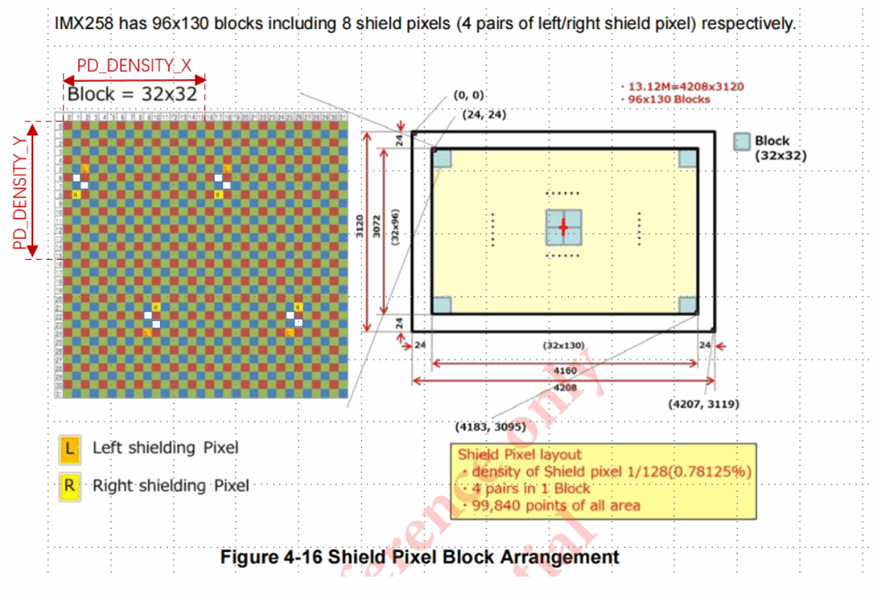
Take the IMX258 pd pixel distribution as an example, as shown in the following figure:
Technical figure from the English source, PDF p.30.
According to the information on the figure, the contents of the sensor.ini file are as follows:
[sensor config]
RAW_WIDTH =4208
RAW_HEIGHT =3120
RAW_BITS =12
RAW_BLACK_LEVEL =64
RAW_BAYER_PATTERN =0
SENSOR_TYPE=0
PD_DUAL_MODE=0
PD_BINNING_TYPE=0
PD_OFFSET_X =24
PD_OFFSET_Y =24
PD_PITCH_X =32
PD_PITCH_Y =32
PD_DENSITY_X =16
PD_DENSITY_Y =16
PD_BLOCK_NUM_X =130
PD_BLOCK_NUM_Y =96
CALB_S_LEVEL=1000
CALB_S_CNT=10
PD_POS_L=
[26 29]
[42 29]
[33 48]
[49 48]; #end with a ";"
PD_POS_R=
[25 32]
[41 32]
[34 45]
[50 45]; #end with a ";"
[Gainmap_Calib]
GAINMAP_BLKSZ_W=16
GAINMAP_BLKSZ_H=16
GAIN_CALIB_INPUT_MAX=920
GAIN_CALIB_INPUT_MIN=800
GAIN_VERIFY_DIFF_MAX=5
CROSS_VER=1
[DCCmap_Calib]
DCCMAP_BLKSZ_W=32
DCCMAP_BLKSZ_H=32
DCC_CALIBRATE_MODE=1
DCC_LENS_BEGIN=0
DCC_LENS_END=64
DCC_LENS_INTERVAL=8
DCC_RSQ_THRESHOLD=0.985
DCC_BORDER_RSQ_THRESHOLD=0.97
DCC_BAD_RSQ_NUM_RATIO=0.05
DCC_CALIB_INPUT_MAX=640
DCC_CALIB_INPUT_MIN=340
DCC_VERIFY_CAF_DIFF_MAX=10
DCC_VERIFY_CAF_DIFF_DET=2
CALIB_TARGET_PEAK_OFFSET_LOG=0
CALIB_TARGET_PEAK_OFFSET=0
DCC_PERCENT_ROI_W=0.4
DCC_PERCENT_ROI_H=0.4
DCC_SHARPNESS_MODE=1
DCC_SHARPNESS_CHL=1
[optional params]
QUALITY_VERIFY_ENABLE=1
QUALTI_LRDiff_L_MIN=0.4
QUALTI_LRDiff_L_MAX=2.5
QUALTI_LRDiff_C_MIN=0.55
QUALTI_LRDiff_C_MAX=1.8
QUALTI_LRDiff_R_MIN=0.4
QUALTI_LRDiff_R_MAX=2.5
QUALITY_SENSITIVITY_MIN=0.45
【Function prototypes】
bool pdaf_initial(char* filename, sensor_cfg* psensor_cfg)
【Iutput information】
| Parameter name | Description |
|---|---|
| filename | The full path of the sensor.ini file |
【Output information】
| Parameter name | Description |
|---|---|
| psensor_cfg | A struct pointer that stores the contents of the sensor.ini file |
【Return value】
=0:Failed to get sensor.ini
=1:Get sensor.ini successfully
3.3.2 Gain Map calibration
【Feature description】
This function is used for the indexing of PDAF gain maps.
【Function prototypes】
bool pdaf_gainmap_calibration(uint16_t *RawAddr, sensor_cfg* psensor_cfg,
                              uint16_t *gainmap_lut,int* gainmap_width,
                              int* gainmap_height)
【Iutput information】
| Parameter name | Description |
|---|---|
| RawAddr | Raw image data captured by the current module on the production line |
| psensor_cfg | A struct pointer that stores the contents of the sensor.ini file |
【Output information】
| Parameter name | Description |
|---|---|
| gainmap_lut | Calibrated gain map |
| gainmap_width | The width of the indexed gain map |
| gainmap_height | The high of the gain map obtained by calibration |
【Return value】
=0:The parameter is incorrect
=1:Calibration successful
3.3.3 Gain Map Validation
【Feature description】
This function is used to verify whether the calibrated gain map meets the requirements.
【Function prototypes】
bool pdaf_gainmap_vertification(uint16_t *RawAddr, sensor_cfg* psensor_cfg,
                                uint16_t *gainmap_lut)
【Iutput information】
| Parameter name | Description |
|---|---|
| RawAddr | Raw image data captured by the current module on the production line |
| psensor_cfg | A struct pointer that stores the contents of the sensor.ini file |
| gainmap_lut | The gain map obtained by the pdaf_gainmap_calibration index |
【Return value】
=0:The validation failed, and the gainmap used for validation did not meet the requirements.
=1:Verification successful
3.3.4 DCC Map calibration
【Feature description】
This function is used for the calibration of PDAF DCC MAP.
【Function prototypes】
bool pdaf_dccmap_calibration(uint16_t *RawAddrAll , sensor_cfg* psensor_cfg,
                             uint16_t *gainmap_lut, uint16_t *dccmap_lut,
                             int* dccmap_width,int* dccmap_height,
                             uint8_t* dccSign,wchar_t*pd_offset)
【Iutput information】
| Parameter name | Description |
|---|---|
| RawAddrAll | The average sequence of image data captured at each motor position |
| psensor_cfg | A struct pointer that stores the contents of the sensor.ini file |
| gainmap_lut | The gain map obtained by the pdaf_gainmap_calibration index |
【Output information】
| Parameter name | Description |
|---|---|
| dccmap_lut | The resulting DCC MAP |
| dccmap_width | The width of the indexed DCC map |
| dccmap_height | The height of the indexed DCC MAP |
| dccSign | Calibrate the orientation of the resulting DCC MAP |
| pd_offset | The pd_offset obtained from the calibration |
【Return value】
=0:Calibration failed
=1:Calibration successful
3.3.5 DCC Map Verification
Used to verify whether the calibrated dcc map meets the requirements, including two function interfaces pdaf_dccmap_vertification() and pdaf_calc_sharpness().
【Function description】
Use the calibrated dcc map to obtain the ideal focus clear position DAC1 of the blurred image;
【function prototype】
uint16_t pdaf_dccmap_vertification(uint16_t *RawAddr, sensor_cfg* psensor_cfg,
                                   int cur_pos_id, uint16_t *gainmap_lut,
                                   uint16_t *dccmap_lut, uint8_t dccSign, wchar_t
*pd_offset)
【Iutput information】
| Parameter name | Description |
|---|---|
| RawAddr | Average image data of captured blurry images |
| psensor_cfg | Structure pointer that stores the contents of the sensor.ini file |
| cur_pos_id | Blurred image taken of current motor position |
| gainmap_lut | gain map calibrated by pdaf_gainmap_calibration |
| dccmap_lut | dcc map calibrated by pdaf_dccmap_calibration |
| dccSign | dccSign calibrated by pdaf_dccmap_calibration |
| pd_offset | The pd_offset obtained by the pdaf_dccmap_calibration calibration |
【Return value】
Motor position DAC1 when blurred image is ideally in focus.
【Function description】
Calculate the sharpness of the image center area within the DCC_VERIFY_CAF_DIFF_MAX*abs (DACinf- DACmacro)+DCC_VERIFY_CAF_DIFF_DET before and after DAC1 to determine whether there is a peak.
【function prototype】
bool pdaf_calc_sharpness(uint16_t *RawAddrAll, int img_num, sensor_cfg*
psensor_cfg)
【Iutput information】
| Parameter name |
Description |
|---|---|
| RawAddrAll | The average image data sequence within valid_toerance*abs (DACinf-DACmacro)+2 before and after DAC1 |
| img_num | Number of images contained in RawAddrAll |
| psensor_cfg | Structure pointer that stores the contents of the sensor.ini file |
【Return value】
=0:No sharpness peak found, verification failed
=1:Verification successful
4 Appendix
4.1 OTP application sample code
#include <iostream>
#include "RKOTPDLL.h"
#include <stdlib.h>
int main()
{
    int ret = 0;
    #LSC AWB Otp Calibration
    ret =lsc_awbtest();
    #Pdaf Otp Calibration
    uint16_t gainmap[30*30 * 2];
    uint16_t dccmap[20 * 20 * 2];
    uint16_t code = 0;
    int gainmap_width = 0;
    int gainmap_height = 0;
    int dccmap_width = 0;
    int dccmap_height = 0;
    uint8_t dcc_Sign = 0;
    wchar_t pd_offset=0xffff;
    int curpos = 864;
    sensor_cfg sensor_param;
    if (pdaf_initial("D:\\testdll\\testdll\\sensor_ov16A10.ini", &sensor_param))
    {
        if (gainmaptest(&sensor_param, gainmap,&gainmap_width,&gainmap_height))
        {
        if (dccmaptest(&sensor_param, gainmap, dccmap, curpos, &code,
&dccmap_width, &dccmap_height, &dcc_Sign,&pd_offset))
            {
                ret = dcc_calc_sharpness(&sensor_param);
            }
        }
    }
}
bool lsc_awbtest()
{
    int vig=70;
    int height = 1944;
    int width = 2592;
    int bits =10;#10bit
    int bayer =0;#BGGR
    int roiw =5;#1/5 width
    int roih =5;#1/5 height
    int blc[4]={ 64, 64, 64, 64};
    uint16_t lsctable[17*17*4];
    uint16_t awb[3];
    uint16_t Rave =0;
    uint16_t Grave =0;
    uint16_t Gbave =0;
    uint16_t Bave =0;
    int Ydiffer_down =0;#%
    int Ydiffer_up =5;#%
    int ColorShading_down =0;#%
    int ColorShading_up =5;#%
    float Ydiffer = 0;
    float RGconer[25];
    float BGconer[25];
    bool ret =0;
    uint16_t *Rawdata = NULL;
    Rawdata = (uint16_t*)malloc(width * height * 2);
    memset(Rawdata, 0, sizeof(uint16_t)* width * height);
    FILE *fp = NULL;
    fp = fopen("input.raw", "rb");
    if (fp == NULL)
    {
        return false;
    }
    fread(Rawdata, 1, height * width * 2, fp);
    fclose(fp);
    ret =lsc_otp_Calibrate(vig,Rawdata, width, height, bits, bayer, blc[0],
blc[1],blc[2], blc[3],lsctable);
    ret = awb_otp_Calibrate(Rawdata, width, height,roiw,roih, bits, bayer,
blc[0], blc[1],blc[2], blc[3],&Rave,&Grave,&Gbave,&Bave, &awb[0], &awb[1],
&awb[2]);
    ret = lsc_otp_verify(Rawdata, width, height, bits, bayer, blc[0], blc[1],
blc[2], blc[3], lsctable, Ydiffer_down, Ydiffer_up, ColorShading_down,
ColorShading_up, &Ydiffer, RGconer, BGconer);
    if(!ret)
    {
        return false; #The calibrated data does not meet the control standards and the verification fails.
    }
    if(Rawdata!=NULL)
    {
        free (Rawdata);
        Rawdata =NULL;
    }
    return ret;
}
int gainmaptest(sensor_cfg* psensor_cfg, uint16_t *gainmap_lut,int *
gainmap_width, int *gainmap_height)
{
    int ret = 0;
    int height = psensor_cfg->height;
    int width = psensor_cfg->width;
    uint16_t maxval = (1 << psensor_cfg->bits) - 1;
    int gainmapfilenum = 3;
    int over_exp_cnt = 0;
    if (psensor_cfg->pd_dual_mode && psensor_cfg->mipi_mix_mode)
    {
        height = psensor_cfg->height + (psensor_cfg->sensor_type+1)*psensor_cfg->pd_height;
    }
    uint16_t *ave_pixelbuf = NULL;
    ave_pixelbuf = (uint16_t*)malloc(width * height * 2);
    memset(ave_pixelbuf, 0, sizeof(uint16_t)* width * height);
    uint16_t *sum_pixelbuf = NULL;
    sum_pixelbuf = (uint16_t*)malloc(width * height * 2);
    memset(sum_pixelbuf, 0, sizeof(uint16_t)* width * height);
    uint16_t *pixelbuf = NULL;
    pixelbuf = (uint16_t*)malloc(width * height * 2);
    memset(pixelbuf, 0, sizeof(uint16_t)* width * height);
    FILE *fp = NULL;
    char prename[20] = "gainRAW";
    char endname[5] = ".raw";
    for (int i = 0; i < gainmapfilenum; i++)
    {
        char temp[20];
        char id[5];
        int idint = i + 1;
        strcpy(temp, prename);
        _itoa_s(idint, id, 10);
        strcat(temp, id);
        strcat(temp, endname);
        fp = fopen(temp, "rb");
        if (fp == NULL)
        {
            return false;
        }
        fread(pixelbuf, 1, height * width * 2, fp);
        fclose(fp);
        for (int j = 0; j < height; j++)
        {
            for (int i = 0; i < width; i++)
            {
                uint32_t tempbuf = *(pixelbuf + j*width + i);
                *(sum_pixelbuf + j*width + i) = tempbuf + *(sum_pixelbuf +
j*width + i);
                if (tempbuf >= maxval)
                    over_exp_cnt++;
            }
        }
    }
    for (int j = 0; j < height; j++)
    {
        for (int i = 0; i < width; i++)
        {
            *(ave_pixelbuf + j*width + i) = *(sum_pixelbuf + j*width + i) /
gainmapfilenum;
        }
    }
    ret = pdaf_gainmap_calibration(ave_pixelbuf, psensor_cfg, gainmap_lut,
gainmap_width,gainmap_height);
    ret = pdaf_gainmap_vertification(ave_pixelbuf, psensor_cfg, gainmap_lut);
    if(ret == -1)
        printf("gainmap image OVER exposure!!!");
    if (ave_pixelbuf!=NULL)
    {
        free(ave_pixelbuf);
        ave_pixelbuf = NULL;
    }
    if (pixelbuf != NULL)
    {
        free(pixelbuf);
        pixelbuf = NULL;
    }
    if (sum_pixelbuf != NULL)
    {
        free(sum_pixelbuf);
        sum_pixelbuf = NULL;
    }
    return ret;
}
bool dccmaptest(sensor_cfg* psensor_cfg, uint16_t *gainmap_lut, uint16_t
*dccmap_lut, int curpos , uint16_t *code, int *dccmap_width, int *dccmap_height,
uint8_t *dcc_Sign,wchar_t *pdaf_offset)
{
    int ret = 0;
    int lens_begin = 0;
    int lens_end = 64;
    int lens_interval = 8;
    int height = psensor_cfg->height;
    int width = psensor_cfg->width;
    int lensnum = (lens_end - lens_begin) / lens_interval + 1;
    if (psensor_cfg->pd_dual_mode && psensor_cfg->mipi_mix_mode)
    {
        height = psensor_cfg->height + (psensor_cfg->sensor_type +
1)*psensor_cfg->pd_height;
    }
    uint16_t *ave_pixelbuf = NULL;
    ave_pixelbuf = (uint16_t*)malloc(width * height * 2);
    memset(ave_pixelbuf, 0, sizeof(uint16_t)* width * height);
    uint16_t *Rawdata = NULL;
    Rawdata = (uint16_t*)malloc(width * height * 2 * lensnum);
    memset(Rawdata, 0, sizeof(uint16_t)* width * height* lensnum);
    uint16_t *pixelbuf= NULL;
    pixelbuf = (uint16_t*)malloc(width * height * 2);
    memset(pixelbuf, 0, sizeof(uint16_t)* width * height);
    FILE *fp = NULL;
    char prename[20] = "dccRAW";
    char endname[5] = ".raw";
    for (int a = 0;a <lensnum;a++)
    {
        char temp[20];
        char id[5] ;
        int id1 = a + 1;
        strcpy(temp,prename);
        _itoa_s(id1, id, 10);
        strcat(temp, id);
        for (int b = 0; b < 3;b++)
        {
            char name[20];
            strcpy(name, temp);
            int id2 = b + 1;
            _itoa_s(id2, id, 10);
            strcat(name, id);
            strcat(name, endname);
            fp = fopen(name, "rb");
            if (fp == NULL)
            {
                return false;
            }
            fread(pixelbuf, 1, height * width * 2, fp);
            fclose(fp);
            for (int j = 0; j < height; j++)
            {
                for (int i = 0; i < width; i++)
                {
                    uint16_t tempbuf = *(ave_pixelbuf + j*width + i);
                    *(ave_pixelbuf + j*width + i) = tempbuf + *(pixelbuf +
j*width + i) / 3;
                }
            }
        }
        memcpy(Rawdata + a*height * width, ave_pixelbuf, sizeof(uint16_t)*height
* width);
        memset(ave_pixelbuf, 0, sizeof(uint16_t)* width * height);
    }
    ret = pdaf_dccmap_calibration(Rawdata, psensor_cfg, gainmap_lut, dccmap_lut,
dccmap_width, dccmap_height, dcc_Sign,pd_offset);
    memset(pixelbuf, 0, sizeof(uint16_t)* width * height);
    memset(ave_pixelbuf, 0, sizeof(uint16_t)* width * height);
    char prename1[20] = "image";
    for (int i = 0; i < 3; i++)
    {
        char temp[20];
        char id[5];
        int idint = i + 1;
        strcpy(temp, prename1);
        _itoa_s(idint, id, 10);
        strcat(temp, id);
        strcat(temp, endname);
        fp = fopen(temp, "rb");
        if (fp == NULL)
        {
            return false;
        }
        fread(pixelbuf, 1, height * width * 2, fp);
        fclose(fp);
        for (int j = 0; j < height; j++)
        {
            for (int i = 0; i < width; i++)
            {
                uint16_t tempbuf = *(ave_pixelbuf + j*width + i);
                *(ave_pixelbuf + j*width + i) = tempbuf + *(pixelbuf + j*width +
i) / 3;
            }
        }
    }
        *code = pdaf_dccmap_vertification(ave_pixelbuf, psensor_cfg, curpos,
gainmap_lut, dccmap_lut, *dcc_Sign,pd_offset);
    if (ave_pixelbuf != NULL)
    {
        free(ave_pixelbuf);
        ave_pixelbuf = NULL;
    }
    if (pixelbuf != NULL)
    {
        free(pixelbuf);
        pixelbuf = NULL;
    }
    if (Rawdata != NULL)
    {
        free(Rawdata);
        Rawdata = NULL;
    }
    return ret;
}
bool dcc_calc_sharpness(sensor_cfg* psensor_cfg)
{
    int height = psensor_cfg->height;
    int width = psensor_cfg->width;
    int imgnum = 5;
    if (psensor_cfg->pd_dual_mode && psensor_cfg->mipi_mix_mode)
    {
        height = psensor_cfg->height + (psensor_cfg->sensor_type +
1)*psensor_cfg->pd_height;
    }
    uint16_t *Rawdata = NULL;
    Rawdata = (uint16_t*)malloc(width * height * 2 * imgnum);
    memset(Rawdata, 0, sizeof(uint16_t)* width * height* imgnum);
    uint16_t *pixelbuf = NULL;
    pixelbuf = (uint16_t*)malloc(width * height * 2);
    memset(pixelbuf, 0, sizeof(uint16_t)* width * height);
    FILE *fp = NULL;
    char prename[20] = "calimage";
    char endname[5] = ".raw";
    for (int i = 0; i < imgnum; i++)
    {
        char temp[20];
        char id[5];
        int idint = i + 1;
        strcpy(temp, prename);
        _itoa_s(idint, id, 10);
        strcat(temp, id);
        strcat(temp, endname);
        fp = fopen(temp, "rb");
        if (fp == NULL)
        {
            return false;
        }
        fread(pixelbuf, 1, height * width * 2, fp);
        fclose(fp);
        memcpy(Rawdata + i*height * width, pixelbuf, sizeof(uint16_t)*height *
width);
    }
    bool ret=pdaf_calc_sharpness(Rawdata, imgnum, psensor_cfg);
    if (pixelbuf != NULL)
    {
        free(pixelbuf);
        pixelbuf = NULL;
    }
    if (Rawdata != NULL)
    {
        free(Rawdata);
        Rawdata = NULL;
    }
    return ret;
}
4.2 Burning packaged data format
As shown in the following table, users can burn certain blocks specified according to their needs (note that the ID of the block is not allowed to be changed), and the 0xff that needs to be burned after the required blocks are burned is completed:
| Length(Byte) | data item | Remark |
|---|---|---|
| 8 | Mark | ROCKCHIP |
| 1 | ID | ID=0,Sensor Info |
| 4 | Size | Block data size |
| block data | ||
| 1 | ID | ID=1,AWB Calibration |
| 4 | Size | Block data size |
| block data | ||
| 1 | ID | ID=2,LSC Calibration |
| 4 | Size | Block data size |
| block data | ||
| 1 | ID | ID=3,PDAF Calibration |
| 4 | Size | Block data size |
| block data | ||
| 1 | ID | ID=4,AF Code |
| 4 | Size | The size of the block data |
| block Data | ||
| 1 | ID | ID=5,QSC |
| 4 | Size | Block data size |
| block data | ||
| … | … | … |
| 1 | 0xFF | end sign |
The specific content of the block is as follows. Multi-byte data is unified in big-endian mode. The high byte is stored in the low address and the low byte is stored in the high address:
| Offset address | Length(Byte) | data item | Remark |
|---|---|---|---|
| 0x0000 | 8 | Mark | ROCKCHIP |
| 0x0008 | 1 | ID | ID=0,Sensor Info |
| 0x0009 | 4 | Size | Size=35 |
| 0x000D | 2 | Version | Sensor Info Version: v1.0.8=0x0108 |
| 0x000F | 1 | Supplier ID | User specified |
| 0x0010 | 1 | Date:Year | For example, in 2021, write 21 |
| 0x0011 | 1 | Date:Month | For example, in July, write 7 |
| 0x0012 | 1 | Date:Day | For example, on the 12th, write 12 |
| 0x0013 | 1 | Sensor ID | User specified |
| 0x0014 | 1 | Lens ID | User specified |
| 0x0015 | 1 | VCM ID | User specified |
| 0x0016 | 1 | Driver ID | User specified |
| 0x0017 | 4 | Module ID | User specified |
| 0x001B | 1 | mirror/flip | Bit[7:4]:Mirror Bit[3:0]:Flip ON: 1, OFF: 0 |
| 0x001C | 1 | Full Width H | Full Width High byte |
| 0x001D | 1 | Full Width L | Full Width Low byte |
| 0x001E | 1 | Full Height H | Full Height High byte |
| 0x001F | 1 | Full Height L | Full Height Low byte |
| 0x0020 | 15 | Reserved | Reserved=0xff |
| 0x002F | 1 | Checksum | Sensor Info Checksum Sum(0x0009~0x002E) % 255+1 |
| Offset address | Length(Byte) | Data item | Remark |
|---|---|---|---|
| 0x0000 | 1 | ID | ID=1,AWB Calibration |
| 0x0001 | 4 | Size | Size=43 |
| 0x0005 | 2 | Version | AWB Version: v1.0.9=0x0109 |
| 0x0007 | 1 | R/G_H | Current R/G value High byte |
| 0x0008 | 1 | R/G_L | Current R/G value Low byte |
| 0x0009 | 1 | B/G_H | Current B/G value High byte |
| 0x000A | 1 | B/G_L | Current B/G value Low byte |
| 0x000B | 1 | Gr/Gb_H | Current Gr/Gb value High byte |
| 0x000C | 1 | Gr/Gb_L | Current Gr/Gb value Low byte |
| 0x000D | 1 | R/G_H | Golden R/G value High byte |
| 0x000E | 1 | R/G_L | Golden R/G value Low byte |
| 0x000F | 1 | B/G_H | Golden B/G value High byte |
| 0x0010 | 1 | B/G_L | Golden B/G value Low byte |
| 0x0011 | 1 | Gr/Gb_H | Golden Gr/Gb value High byte |
| 0x0012 | 1 | Gr/Gb_L | Golden Gr/Gb value Low byte |
| 0x0013 | 28 | Reserved | Reserved=0xff |
| 0x002F | 1 | Checksum | AWB Calibration Checksum Sum(0x0001~0x002E) % 255+1 |
| Offset address |
Length(Byte) | Data item | Remark |
|---|---|---|---|
| 0x0000 | 1 | ID | ID=2,LSC Calibration |
| 0x0001 | 4 | Size | Size=2347 |
| 0x0005 | 2 | Version | LSC Version: v1.0.b=0x010b |
| 0x0007 | 2312 | LSC Calibation Data |
17x17x4matrix fixed to 1024, unpackaged, big endian, the stored channel order is R, Gr, Gb, B |
| 0x090F | 32 | Reserved | Reserved=0xff |
| 0x092F | 1 | Checksum | LSC CalibrationChecksum Sum(0x0001~0x092E) % 255+1 |
| Offset address |
Length(Byte) | Data item | Remark |
|---|---|---|---|
| 0x0000 | 1 | ID | ID=3,PDAF Calibration |
| 0x0001 | 4 | Size | Size=2603 |
| 0x0005 | 2 | Version | PDAF Version: v1.1.12=0x011c |
| 0x0007 | 1 | Gainmap_width | Gainmap size,get from pdaf_gainmap_calibration() |
| 0x0008 | 1 | Gainmap_height | Gainmap size,get from pdaf_gainmap_calibration() |
| 0x0009 | 2048 | Gainmap | Actual size=Gainmap_width* Gainmap_height*2,big endian,Default value: 0xff |
| 0x0809 | 1 | Checksum | Gainmap Checksum Sum(0x0007~0x00808) % 255+1 |
| 0x080A | 1 | mode value | DCC Map Fit mode (this version defaults to 1), consistent with DCC_CALIBRATE_MODE in pd ini configuration |
| 0x080B | 1 | direction | dccSign,get from pdaf_dccmap_calibration() 0: negative 1: positive |
| 0x080C | 1 | DCCmap_width | DCCmap size,get from pdaf_dccmap_calibration() |
| 0x080D | 1 | DCCmap_height | DCCmap size,get from pdaf_dccmap_calibration() |
| 0x080E | 512 | Dccmap | Actual size=DCCmap_width* DCCmap_height*2,big endian,Default value: 0xff |
| 0x0A0E | 1 | Checksum | DCCmap Checksum Sum(0x080A~0x0A0D) % 255+1 |
| 0x0A0F | 2 | pd_offset | flag(1)sign(1)reserve(2)integer(4)8fix_decimals(8) ,flag=0:calib sign=1:positive |
| 0x0A11 | 30 | Reserved | Reserved=0xff |
| 0x0A2F | 1 | Checksum | PDAF Calibration Checksum Sum(0x0001~0x0A2E) % 255+1 |
| Offset address | Length(Byte) | Data item | Remark |
|---|---|---|---|
| 0x0000 | 1 | ID | ID=4,AF Code |
| 0x0001 | 4 | Size | Size=27 |
| 0x0005 | 2 | Version | AF Version: v1.0.9=0x0109 |
| 0x0007 | 1 | AF Infinite H | AF far focus Code value high bit |
| 0x0008 | 1 | AF Infinite L | AF far focus Code value low |
| 0x0009 | 1 | AF Macro H | AF close focus Code value high |
| 0x000A | 1 | AF Macro L | AF close focus Code value low |
| 0x000B | 1 | AF_Medium H | AF medium focus Code value high |
| 0x000C | 1 | AF_Medium L | AF medium focus Code value low |
| 0x000D | 18 | Reserved | Reserved=0xff |
| 0x001F | 1 | Checksum | AF Code Checksum Sum(0x0001~0x001E) % 255+1 |
| Offset address |
Length(Byte) | Data items |
Remark |
|---|---|---|---|
| 0x0000 | 1 | ID | ID=5,QSC |
| 0x0001 | 4 | Size | Size=4107 |
| 0x0005 | 2 | Version | QSC Version: v1.0.0=0x0100 |
| 0x0007 | 2 | QSC Size | QSC Size, big endian |
| 0x0009 | 4096 | Data | For QSC Data, the actual write size is based on the QSC size, and the default value is 0xff |
| 0x1009 | 6 | Reserved | Reserved=0xff |
| 0x100F | 1 | Checksum | QSC Checksum Sum(0x0001~0x100E) % 255+1 |