
This is a source-derived platform reference, not an ArmSoM validation report. It applies at SoC/BSP level to boards using a documented supported SoC, including Sige7/AIM7 (RK3588) and Sige5/CM5/AIM5 (RK3576). Confirm the exact CRU register map, PLL parent tree, downstream consumers and released boot firmware/kernel before writing a register. No ArmSoM EMI, jitter, stability or certification measurement was performed.
Source: Rockchip PLL Frequency Spreading Function Detailed Explanation, V1.8.0, 2025-04-16. Chinese source has 13 pages; English source has 12 pages because its revision history is separate. Chinese pages 6–7 and English pages 5–6 contain the corresponding source diagrams. Cover/legal material, intended audience and revision history are omitted. Editorial notes.
1. Spread-spectrum concept
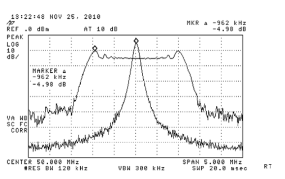
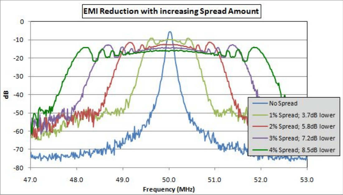
Clock edges are often the highest-frequency signals in a system and a common source of EMI. Spread-spectrum clock generation (SSCG/SSG) modulates clock frequency to distribute energy that would otherwise concentrate in a narrow frequency band; this lowers fundamental and odd-harmonic peaks. It is a system-level technique because synchronous data, address and control signals are modulated with the clock source.
1.1 Parameters
- Modulation rate: how rapidly output frequency moves across the configured range. It should be far below source clock frequency to avoid setup/hold problems, yet above the audible 20 Hz–20 kHz region. The source states a typical 30–120 kHz range.
- Modulation depth: frequency deviation from source frequency, expressed as a percentage. Greater depth generally lowers EMI peaks but must remain inside what the system can tolerate.
2. PLL parameter configuration
2.1 General PLLs (except RK3588)
- Enable fractional mode: set
dsmpd = 0. A PLL without fractional mode does not support spread spectrum. - Set
ssmod_reset = 0,ssmod_disable_sscg = 0, andssmod_bp = 0. - Set amplitude with
ssmod_spread = n,n = 0…0x1f;nrepresents0.n%. - Set rate with
ssmod_divval = n,n = 0…0xf.
spread-spectrum rate (Hz) = 24000000 / refdiv / 128 / n
refdiv is a PLL parameter, normally 1 according to the source; verify the target TRM. RK3399 alone requires an external vector table: set ssmod_sel_ext_wave = 1 and ssmod_ext_maxaddr = 0xff.
2.2 RK3588 PLLs
- Set
sscg_en = 1to enable dithered mode (0disables it). - Set amplitude using
mrr = 0…63; source formula:MR = mfr * mrr / m / 32. - Set rate using
mfr = 0…255; source formula:MF = Fin / p / mfr / 32. - Set
sel_pf:0down spread,1up spread,1xcenter spread. The source generally recommends center spread because of jitter.
3. Register examples
These examples are source commands, not universal safe recipes. Addresses, target PLLs and bit encodings are SoC-specific.
# RK3399 GPLL
io -4 0xff760094 0x00010001
io -4 0xff760090 0x1f000100
io -4 0xff760090 0x00f000f0
io -4 0xff760094 0xff00ff00
io -4 0xff76008c 0x00080000
io -4 0xff760090 0x00070000

# RK3328 CPLL / PX30 GPLL / RK3308 VPLL0 / RV1126 HPLL / RK1808 GPLL
# use each target's CRU base address; amplitude is 0x1f000800,
# rate is 0x00f00060, then fractional mode and SSMOD enable.

# RK356X GPLL
io -4 0xfdd2004c 0x1f000800
io -4 0xfdd2004c 0x00f00060
io -4 0xfdd20044 0x10000000
io -4 0xfdd2004c 0x00070000

# RK3588 GPLL
io -4 0xfd7c01cc 0x00ff000c
io -4 0xfd7c01cc 0x3f000500
io -4 0xfd7c01cc 0xc0008000
io -4 0xfd7c01d0 0x00010001

# RK3576 GPLL
io -4 0x272001cc 0x00ff000c
io -4 0x272001cc 0x3f000500
io -4 0x272001cc 0xc0008000
io -4 0x272001d0 0x00010001
The source also gives equivalent general-PLL examples for RK3528 (0xff4a006c/0xff4a0064), RK3562 (0xff10006c/0xff100064), RK2118 V0PLL (0x50b1002c/0x50b10024), RV1103B (0x2006006c/0x20060064), RK3506 (0xff9b000c/0xff9b0004), and RV1126B/RV1126B-P (0x2000002c/0x20000024). Their sequences retain the same amplitude/rate/fractional-mode/enable ordering shown above; use the source PDF and target TRM for every full write value. RK3036, RK312X, RK322X, RK3188, RK3288 and RK3368 do not support this function according to the source.
The suggested rate is 30 kHz. The source gives no universal amplitude: determine it by laboratory measurement and EMI certification. Similar PLLs require the matching PLL base address, not copied addresses.
4. Persistent configuration
When parameters are settled, configure them early. For RK3399 the source shows U-Boot writes in drivers/clk/rockchip/clk_rk3399.c and kernel writes in drivers/clk/rockchip/clk-rk3399.c, after clock initialization and before registering the provider. For DPLL/DDR SSC, apply it in the loader: changing DDR clock elsewhere can make the system unstable or crash.
Representative RK3399 U-Boot sequence:
writel(0x1f001f00, &priv->cru->dpll_con[4]);
writel(0x00f00060, &priv->cru->dpll_con[4]);
writel(0x7f002700, &priv->cru->dpll_con[5]);
writel(0x00080000, &priv->cru->dpll_con[3]);
writel(0x00070000, &priv->cru->dpll_con[4]);
writel(0x00010001, &priv->cru->dpll_con[5]);
5. Engineering limits and validation
SSCG is inappropriate for some precision-sensitive clocks, including Ethernet and CAN. It introduces jitter and can cause setup/hold errors, high error rates or PLL lock loss. The source estimates added period jitter below approximately 0.05%, but that is not a board-level guarantee.
Enabling PLL SSC affects all self-clocks below that PLL. Shared consumers such as eMMC and SDIO can have different EMI needs, so choose a compromise only after validating both. DDR, USB, SDIO, I2C, SPI, I2S, USB3.0, PCIe and eDP may define SSC requirements; use their specifications. Enable SSC only when necessary, and use the smallest depth that satisfies EMI. USB2.0 can fail frequency tests after SSC; PHY elastic-buffer size affects tolerance. Treat every project as a separate stability and compatibility case.