
This guide is for audio development on ArmSoM Rockchip platforms, including Sige7 / AIM7 (RK3588) and Sige5 / CM5 / AIM5 (RK3576). Select the relevant sections for your SoC, onboard or carrier-board codec, wiring and SDK/BSP. A controller capability does not mean that every board exposes that interface. The source covers Linux 4.4, 4.19, 5.10 and 6.1; check drivers and Device Tree properties against the matching BSP. Measurements and examples are from Rockchip, not ArmSoM hardware tests.
Source: Rockchip_Developer_Guide_Audio_EN.pdf, V2.4.0. Technical chapters are retained; cover declarations, intended audience and revision history are omitted. See the editorial notes for corrections and unresolved issues.
ArmSoM Docs · Sige7 · Sige5 · CM5
1. Overview
1.1 Rockchip Audio Features
This section describes the audio features of the RK platform.
| Function | Feature | Description | |
|---|---|---|---|
| DAI | I2S | 8 CH IN / OUT | Inter IC Sound |
| TDM | 16 CH IN / OUT | Time Division Multiplexing | |
| PCM | 2 CH IN / OUT | Pulse Code Modulation | |
| PDM | 8 CH IN | Pulse Density Modulation | |
| DSM | 2 CH OUT | Delta Sigma Modulation | |
| DCODEC | 4 CH IN / 2 CH OUT | Digital Codec Interface | |
| SPDIF | 2 CH IN / OUT / 7.1 BITSTREAM | Sony/Philips Digital Interface | |
| SAI | 128 CH IN / OUT | Serial Audio Interface | |
| ASRC | 8 CH IN / OUT | Asynchronous Sample Rate Converter | |
| COMBO DAI | I2S + I2S | 16 CH IN / OUT | e.g. Sound Bar Product |
| I2S + PDM | 16 CH IN / OUT | e.g. Smart Home Product | |
| TDM + TDM | 32 CH IN / 32 CH OUT | ||
| TDM + PDM | 24 CH IN / 16 CH OUT | ||
| SAI + SAI | 256 CH IN / OUT or More | e.g. Mic Array | |
| ASRC + ASRC | 40 CH | e.g. rk2118 32 CH IN / 8 CH OUT | |
| … | … | … | |
| COMBO CODEC | DMIC ARRAY + ANALOG LOOPBACK | For Acoustic Echo Cancellation | e.g. Smart Home Product |
| HDMI + ANALOG OUTPUT | For Multi Streaming | e.g. OTT Product | |
| CARD + VAD | For Automatic Speech Recognition | e.g. Smart Home Product | |
| DIGITAL OUTPUT | HDMI OUT | 7.1 LPCM Multi Channel / Bitstream | e.g. Dolby / DTS Lossless Bitstream |
| DP | 7.1 LPCM Multi Channel | e.g. Dolby / DTS Lossless Bitstream | |
| OPTICAL | 2 CH LPCM / 7.1 Bitstream | e.g. 7.1 DD+ Bitstream | |
| DCODEC | Link with External Analog Part | e.g. RK812 | |
| DSM | Stereo Differential Output | e.g. Play Music over DSM on RV1126 | |
| DIGITAL INPUT | HDMI IN | HDMI INPUT | e.g. with Third Part IC, e.g. TC358749 |
| HDMI ARC | Audio Return Channel | e.g. RK3308 | |
| PDM DMICS | DMIC Array | e.g. 8 Omnidirectional PDM Mics | |
| I2S DMICS | DMIC Array | e.g. 8 Omnidirectional I2S Mics | |
| DCODEC | Link with External Analog Part | e.g. RK812 | |
| VAD | Voice Activity Detection | Wake Up System if Sound Threshold Reached | |
| SPDIF IN | 2 CH LPCM | e.g. ARC on RK3308 | |
| ANALOG IO | INTERNAL CODECS | 2 CH IN / OUT or More | 8CH IN on RK3308 |
| EXTERNAL CODECS | 2 CH IN / OUT or More | e.g. RK817 | |
| OTHERS | ACC | Audio Clk Compensation (SW / HW) | e.g. UAC for clk drift and compensation |
| DLP | Digital Loopback (SW / HW) | e.g. 2 CH Mics with Digital Loopback | |
| AUPLL-IO-IN | Audio PLL with Clk Sustain | e.g. rk2116 external amp for vehicle |
Figure 1-1 Rockchip Audio Features
1.2 DAI
This chapter mainly describes the support for digital audio interfaces on the RK platform.
1.2.1 SAI
1.2.1.1 SAI Controller Features
Supports flexible protocols, including common I2S/DSP/TDM, etc.
Supports FSYNC ERR / LOST detection
Supports FSYNC/SCLK INV
Supports FSYNC formats with any duty cycle
Supports flexible DATA timing adjustment. SFT adjustment unit is half SCLK
Supports Mono: RX supports optional Slot, TX supports Mono copied to all Slots
Supports Master/Slave mode, the mode applies to both TX/RX logic simultaneously
Supports 128 slots per lane (subject to clock constraints, e.g., 50M: TDM 32 slots @ 48k 32 bits)
Supports configurable slot bit width: 8 ~ 32 bits
Supports slot mask
Supports full data line mapping, can remap the relationship between data line and path
Supports TX Auto Stop Mode
Supports TX->RX Loopback
Supports Multi SAI Combined (MSC)
1.2.1.2 RK Series Chips SAI Support List
The table below lists the SAIs available for peripheral use:
| SAIx | RX Lanes | TX Lanes | Version | Note |
|---|---|---|---|---|
| RK1820 SAI-M0 | 4* | 4* | V4 | SDI0~3 and SDO3~0 multiplexed |
| RK1820 SAI-M1/M2 | 4 | 4 | V4 | |
| RK2116 SAI0-RMIO | 4 | 4 | V5 | Matrix IO full multiplexed |
| RK2116 SAI1/2/3-RMIO | 2 | 2 | V5 | |
| RK2116 SAI4/5/6/7-RMIO | 1 | 1 | V5 | |
| RK2118 SAI0/4-RMIO | 4 | 4 | V2 | |
| RK2118 SAI1/2/3/5/6/7- RMIO | 2 | 2 | V2 | |
| RK3528 SAI0 | 1 | 1 | V1 | |
| RK3528 SAI1 | 4 | 4 | V1 | |
| RK3506 SAI0-M0/RMIO | 4 | 1 | V2 | |
| RK3506 SAI1-M0/RMIO | 1 | 4 | V2 | |
| RK3506 SAI2-M0/M1 | 1 | 1 | V2 | |
| RK3506 SAI3-M0 | 1 | 1 | V2 | |
| RK3562 SAI0-M0 | 4* | 4* | V1 | SDI1~3 and SDO3~1 multiplexed |
| RK3562 SAI0-M1 | 4 | 4 | V1 | |
| RK3562 SAI1-M0 | 4 | 4 | V1 | |
| RK3562 SAI1-M1 | 4* | 4* | V1 | SDI1~3 and SDO3~1 multiplexed |
| RK3562 SAI2 | 1 | 1 | V1 | |
| RK3576 SAI0-M0 | 4 | 4 | V1 | |
| RK3576 SAI0-M1/M2 | 4* | 4* | V1 | SDI1~3 and SDO3~1 multiplexed |
| RK3576 SAI1-M0 | 4* | 4* | V1 | SDI1~3 and SDO3~1 multiplexed |
| RK3576 SAI1-M1 | 4 | 4 | V1 | |
| RK3576 SAI2-M0/M1/M2 | 1 | 1 | V1 | |
| RK3576 SAI3-M0/M1/M2/M3 | 1 | 1 | V1 | |
| RK3576 SAI4-M0/M1/M2/M3 | 1 | 1 | V1 | |
| RV1103B SAI | 1 | 1 | V3 | |
| RV1126B SAI0-M0/M1 | 4* | 4* | V4 | SDI1~3 and SDO3~1 multiplexed |
| RV1126B SAI1-M0/M1/M2 | 1 | 1 | V4 | |
| RV1126B SAI2-M0/M1 | 3 | 1 | V4 |
Table 1-2 RK Series Chips SAI Support List
1.2.1.2.1 SAI Version Description
| Version | Description |
|---|---|
| V1 | 1, First Version |
| V2 | 1, Support Frame Sync xN (FSXN) 2, Support Frame Sync Error Detect (FSE) 3, Support Frame Sync Lost Detect (FSLOST) 4, Support SAI Chained 5, Support Transmit Auto Gate Mode 6, Support Timing Shift Left for TX |
| V3 | 1, Support Loopback LR Select (e.g. L:MIC R:LP) |
| V4 | 1, Enhance Frame Integrity Robustness 2, Support FIFO Interleaved Cfg 3, Support Data Debug |
| V5 | 1, Support MSC V2 2, Fsync Clk Phase sync with MAC.pps 3, Clk Sync with USB or MAC by ACC 4, Support Data Debug by ch ID |
Table 1-3 SAI Version Description
1.2.2 ASRC
1.2.2.1 ASRC Controller Features
Supports sample rate conversion 8k ~ 384k
Supports input/output sample rate conversion with ratio from 1:8 to 8:1.
Supports asynchronous clock source synchronization.
Supports THD +N -120dB ~ -140dB @ 24bits
Supports real-time mode
Supports file mode
Supports low latency
Supports Multi ASRC Combined
1.2.2.2 THD+N
Test environment: AP -> SAI -> ASRC -> SAI -> AP
1.2.2.2.1 16bits
The table below shows THD+N(dB) for 16bits. It does not show the obvious optimal performance at integer multiples as in 24bits, and the overall difference is small.
| SR\RSR | 8k | 11.025k | 12K | 16K | 22.05K | 24K | 32K | 44.1K | 48K | 64K |
|---|---|---|---|---|---|---|---|---|---|---|
| 8K | -96.2 | -96.0 | -95.9 | -96.0 | -95.7 | -95.8 | -95.7 | -95.6 | -95.7 | -95.6 |
| 11.025K | -96.6 | -95.9 | -95.8 | -95.8 | -95.6 | -95.6 | -95.5 | -95.5 | -95.5 | -95.5 |
| 12K | -96.7 | -96.0 | -96.1 | -95.5 | -95.7 | -95.5 | -95.5 | -95.5 | -95.5 | -95.5 |
| 16K | -97.2 | -96.5 | -96.3 | -95.6 | -95.5 | -95.5 | -95.5 | -95.4 | -95.4 | -95.4 |
| 22.05K | -97.7 | -97.0 | -96.8 | -96.2 | -95.4 | -95.5 | -95.4 | -95.3 | -95.3 | -95.3 |
| 24K | -97.7 | -97.1 | -96.9 | -96.3 | -95.6 | -95.5 | -95.5 | -95.3 | -95.3 | -95.3 |
| 32K | -97.8 | -97.4 | -97.3 | -96.7 | -96.2 | -96.0 | -95.4 | -95.3 | -95.3 | -95.3 |
| 44.1K | -98.3 | -97.7 | -97.7 | -97.1 | -96.6 | -96.5 | -96.0 | -95.2 | -95.2 | -95.2 |
| 48K | -98.3 | -97.7 | -97.7 | -97.2 | -96.7 | -96.6 | -96.1 | -95.5 | -95.2 | -95.3 |
| 64K | -98.2 | -98.0 | -98.0 | -97.5 | -97.1 | -96.9 | -96.5 | -96.0 | -95.8 | -95.3 |
Table 1-4 16bits THD+N (dB)
1.2.2.2.2 24bits
The table below shows THD+N(dB) for 24bits. The results show that integer multiple conversion yields the best performance.
| SR\RSR | 8k | 11.025k | 12K | 16K | 22.05K | 24K | 32K | 44.1K | 48K | 64K |
|---|---|---|---|---|---|---|---|---|---|---|
| 8K | -141.3 | -132.4 | -133.6 | -139.8 | 132.4 | -135.0 | -137.1 | -132.1 | -133.7 | -133.1 |
| 11.025K | -131.8 | -140.8 | -134.0 | -133.0 | -137.3 | -131.3 | -133.0 | -138.2 | -131.1 | -132.2 |
| 12K | -138.4 | -131.0 | -140.9 | -131.5 | -131.4 | -129.5 | -132.4 | -131.1 | -131.6 | -131.1 |
| 16K | -143.0 | -130.0 | -138.1 | -140.0 | -133.3 | -134.0 | -140.7 | -133.0 | -135.0 | -133.6 |
| 22.05K | -129.8 | -142.9 | -132.0 | -131.5 | -140.5 | -129.5 | -128.7 | -140.3 | -129.4 | -129.8 |
| 24K | -144.0 | -127.3 | -142.8 | -136.3 | -130.5 | -140.7 | -132.7 | -129.8 | -140.1 | -132.6 |
| 32K | -142.0 | -136.5 | -141.7 | -141.8 | -127.7 | -133.8 | -140.5 | -132.6 | -134.5 | -131.7 |
| 44.1K | -139.8 | -144.7 | -139.3 | -128.6 | -142.8 | -132.3 | -132.2 | -140.5 | -129.0 | -129.2 |
| 48K | -142.6 | -122.5 | -144.4 | -143.3 | -126.1 | -142.7 | -138.8 | -130.2 | -140.5 | -137.3 |
| 64K | -142.8 | -141.9 | -142.2 | -143.0 | -139.0 | -139.2 | -142.5 | -128.5 | -134.9 | -140.4 |
Table 1-5 24bits THD+N (dB)
1.2.2.3 Latency
Latency = Phase Delay + FIFO Delay.
1.2.2.3.1 Phase Delay
RATIO = Sample Rate (output) / Sample Rate (input)
| RATIO | Phase Delay |
|---|---|
| RATIO <= 1 | 32 samples @ SR(input) |
| RATIO > 1 | 32 * ratio samples @ SR(input) |
1.2.2.3.2 FIFO Delay
FIFO Delay = ASRC_IN_THRESH + ASRC_OUT_THRESH.
This parameter is configurable. The current software configuration is as shown in the table:
| Thresh | Value |
|---|---|
| ASRC_IN_THRESH | 2 |
| ASRC_OUT_THRESH | 24 |
1.2.2.3.3 Example
| Case | Latency |
|---|---|
| 48k -> 16k | Latency = 32 + 2 + 24 = 58 samples @ 48k, 1.2ms |
| 48k -> 48k | Latency = 32 + 2 + 24 = 58 samples @ 48k, 1.2ms |
| 48k -> 96k | Latency = 32 * (96 / 48) + 2 + 24 = 90 samples @ 48k, 1.9ms |
Note: To optimize latency, adjust FIFO Delay.
1.2.2.4 RK Series Chips ASRC Support List
| Chip | ASRC | Max Capability | Version |
|---|---|---|---|
| RK2118 | ASRC_8CH x 2, ASRC_4CH x 6 | 40 CH | V1 |
| RK3506 | ASRC_4CH x 2 | 8 CH | V1 |
| RK3576 | ASRC_4CH x 2, ASRC_2CH x 2 | 12 CH | V1 |
| RV1126B | ASRC_2CH x 2 | 4 CH | V1 |
1.2.3 I2S
The RK platform has two types of I2S controllers: I2S and I2S-TDM. The I2S controller supports I2S and PCM protocols; the I2S-TDM controller supports I2S, PCM, and TDM protocols.
1.2.3.1 I2S Controller Features
Supports 8-channel I2S protocol: standard, left justified, right justified
Supports stereo PCM protocol: early, late 1, late 2, late 3
Supports master/slave mode, the mode applies to both TX/RX logic simultaneously
Supports sample rates from 8k ~ 192k, 384k sample rate
Supports bit width 16 ~ 32 bits
Supports MSB/LSB mode
Supports clock phase adjustment
Supports clock compensation
Note:
The 384k sample rate requires a high-precision clk, which can be imported from the MCLK PIN externally or use slave mode.
Does not support mono PCM. If needed, use stereo PCM to transmit mono PCM, with valid data placed in slot 0.
Clock compensation is used for clock compensation in systems with different sources, such as UAC, but has usage condition restrictions. Refer to the Audio Clock Compensation chapter.
1.2.3.2 I2S-TDM Controller Features
In addition to the functions supported by the I2S controller, the I2S-TDM controller adds support for the following functions:
Supports 8 slots TDM PCM protocol: normal, left shift mode[0~3]
Supports 8 slots TDM I2S protocol: normal, left justified, right justified
Supports configurable slot bit width: 16 ~ 32 bits
Supports full data line mapping, can remap the relationship between data line and path
Supports TX/RX asynchronous mode, independent clocks, can support independent sample rates, bit widths, protocols
Supports TX/RX synchronous mode, shared clock
Supports PCM FSYNC width configuration: [1~7] sclk cycle or one channel block
Supports I2S FSYNC width configuration: half frame / whole frame
Note:
Slots only support even configuration.
In TDM I2S long frame mode, it can support 16-channel transmission.
Under the TDM protocol, only path-0 is used. Therefore, when the physical connection PIN does not correspond to the channel, please use data line remapping to path-0.
1.2.3.3 RK Series Chips I2S Support List
| Chip | I2S | I2S-TDM |
|---|---|---|
| PX30/RK3326 | I2S1_2CH, I2S2_2CH | I2S0_8CH |
| RK1808 | I2S1 | I2S0 |
| RK3036 | I2S0 | |
| RK3066 | I2S0, I2S1, I2S2 | |
| RK312X | I2S_8CH, I2S_2CH | |
| RK3188 | I2S0 | |
| RK3288 | I2S0 | |
| RK322X | I2S0, I2S1, I2S2 | |
| RK3308 | I2S_2CH_0, I2S_2CH_1 | I2S_8CH_0, I2S_8CH_1, I2S_8CH_2, I2S_8CH_3 |
| RK3328 | I2S0, I2S1, I2S2 | |
| RK3368 | I2S_8CH, I2S_2CH | |
| RK3399 | I2S0, I2S1, I2S2 | |
| RK3568/RK3566 | I2S0_8CH, I2S1_8CH, I2S2_2CH, I2S3_2CH | |
| RK3588 | I2S2_2CH, I2S3_2CH | I2S0_8CH, I2S1_8CH |
| RV1108 | I2S0, I2S1, I2S2 | |
| RV1126/RV1109 | I2S1_2CH, I2S2_2CH | I2S0_8CH |
Table 1-6 RK Series Chips I2S Support List
1.2.4 PDM
The RK platform supports PDM protocol digital mics or ADCs. Specific features are as follows:
1.2.4.1 PDM Controller Features
Supports master mode only
Supports up to 8 MIC arrays
Supports 16 ~ 24 bits bit width
Supports 8 ~ 48k sample rate
Supports channel swap
Supports high-pass filtering: 3.79 Hz, 60 Hz, 243 Hz, 493 Hz
Supports storage alignment: left-aligned, right-aligned
Supports full data line mapping
Supports clock phase adjustment
Supports clock compensation
Note:
Storage alignment is only for formats with bit width greater than 16 bits. For formats greater than 16 bits, data is stored by word, and the lower bits are padded with 0 by default.
Clock compensation is used for clock compensation in systems with different sources, such as UAC, but has usage condition restrictions. Refer to the Audio Clock Compensation chapter.
Full data line mapping function is only supported on RV1126 and subsequent chips: RV1126/RV1109, RK3568/RK3566…
1.2.4.2 RK Series Chips PDM Support List
| Chip | Name | Max Channel | Version |
|---|---|---|---|
| PX30/RK3326 | PDM | 8 | V2 |
| RK1808 | PDM | 8 | V2 |
| RK2108 | PDM | 4 | V3 |
| RK3308 | PDM_8CH | 8 | V2 |
| RK3328 | PDM | 8 | V1 |
| RK3568/RK3566 | PDM | 8 | V3 |
| RV1126/RV1109 | PDM | 8 | V3 |
Table 1-7 RK Series Chips PDM Support List
Version Description
| Version | Description |
|---|---|
| V1 | 1. Supports standard mode, corresponding clocks: 2.048/2.822/3.072 MHz. |
| V2 | 1. Added fractional division. 2. Added storage alignment mode. |
| V3 | BUG FIX: 1. Fixed sign bit overflow issue when input signal amplitude is close to 0 db with HPF enabled. 2. Fixed passband ripple consistency issue, new version passband ripple is less than 0.1 db. 3. Fixed aliasing issue. Features: 1. Added low-power mode, corresponding clocks 1.024/1.411/1.536 MHz. 2. Added high-performance mode, corresponding clocks 4.096/5.644/6.144 MHz. |
Table 1-8 PDM Version Description
1.2.5 DCODEC
The RK platform supports the digital CODEC interface, which can interface with analog CODECs that support this protocol, such as RK812, to form a complete CODEC.
Additionally, when the controller works in DSM mode, it can drive an external PA to meet the needs of ordinary sound quality products, saving costs.
Supports 3-channel ADC
Supports stereo DAC
Supports asynchronous mode: playback and recording sample rates can be different.
Supports synchronous mode: playback and recording sample rates must be the same.
Supports PGA / ALC
Supports DSM output, directly driving PA
Supports high-pass filtering
1.2.6 VAD
Voice Activity Detection (VAD). VAD receives data from the DAI, performs statistical analysis, and triggers an interrupt to wake up the system when a preset threshold is reached. A brief data flow diagram is shown in Figure 1-1:
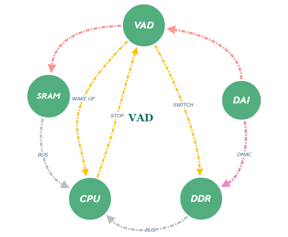
Figure 1-1 RK VAD Data Flow
- When the system is suspend, DAI -> VAD -> SRAM keeps working. VAD continuously receives data, filters and self-learning noise and stores audio data in the SRAM circular buffer.
- When VAD detects that the sound exceeds the preset threshold, it generates an interrupt to wake up the CPU. The CPU turns off VAD. When VAD is turned off, the data flow automatically switches to the DMAC path, i.e., the standard recording path: DAI -> DMAC -> DDR -> CPU.
- The CPU seamlessly fills the data from the SRAM into the recording buffer. Data processing is transparent to the user mode.
- After waking up, the ASR program analyzes the captured data for processing, keyword detection, etc.
1.2.7 SPDIF
The RK platform supports the SPDIF Transmitter interface protocol. Specifically, RK3308 also supports SPDIF Receiver.
Supports 16 ~ 24 bits width
Supports 192k sample rate
Supports stereo uncompressed audio, i.e., LPCM
Supports 5.1 / 7.1 compressed audio, e.g., DD, DD+
Supports Optical, Coaxial
Note:
When outputting at 192k sample rate, Optical components supporting 192k are required.
1.3 Combo DAI
The RK platform supports the combined use of any DAI, reorganizing DAI to generate Combo DAI, as shown in Figure 1-2:
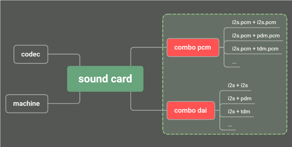
Figure 1-2 Combo DAI
2. Audio Driver Development
This chapter describes the audio support on the RK platform, driver development, and debugging.
2.1 Basic Sound Card Composition
This section introduces the basic composition of a sound card, as shown in Figure 2-1:
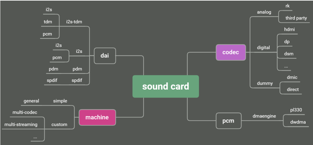
Figure 2-1 ALSA Sound Card Composition
DAI: Digital Audio Interface.
MACHINE: Link dai and codec to be a new sound card.
DMAENGINE: Transfer data between memory and dai’s fifo.
In general, adding a sound card based on the released SDK only requires porting or writing a codec driver. In some cases, a machine driver may also need to be added. For details, see the Machine Driver Development chapter.
2.2 Driver List
The driver list and description are as follows:
kernel/sound/soc/rockchip$ tree -I "*.o|*.h"
.
├── rockchip_asrc.c                             # asynchronous sample rate converter
├── rockchip_dlp.c                              # digital audio loopback
├── rockchip_dlp_pcm.c                          # for single dai dlp
├── rockchip_dummy_dai.c                        # used for multi-dais as channel map
├── rockchip_hdmi_analog.c                      # hdmi and codec share the same i2s
├── rockchip_hdmi.c                             # hdmi with jack det
├── rockchip_hdmi_dp.c                          # hdmi and dp share the same i2s
├── rockchip_i2s.c                              # old i2s which support i2s/pcm
├── rockchip_i2s_tdm.c                          # new i2s-tdm which support i2s/pcm/tdm
├── rockchip_multicodecs.c                      # support multi-streaming
├── rockchip_multi_dais.c                       # support combo-dais
├── rockchip_multi_dais_pcm.c                   # co-work with combo-dais
├── rockchip_pdm.c                              # pdm dai driver
├── rockchip_pdm_v2.c                           # pdmv2 dai driver
├── rockchip_sai.c                              # sai dai driver
├── rockchip_spdif.c                            # spdif tx dai driver
├── rockchip_spdifrx.c                          # spdif rx dai driver
├── rockchip_trcm.c                             # used for i2s-tdm
├── rockchip_utils.c                            # common utils
kernel/sound/soc/codecs$ tree -P "rk*.c|h*.c|d*.c"
.
├── dmic.c                                      # dmic, e.g. i2s dmics, pdm dmics
├── dummy-codec.c                               # dummy codec
├── hdmi-codec.c                                # hdmi codec driver
├── rk312x_codec.c                              # internal codec
├── rk3228_codec.c                              # internal codec
├── rk3308_codec.c                              # internal codec 8ch adc
├── rk3328_codec.c                              # internal codec
├── rk3506_codec.c                              # internal codec
├── rk3528_codec.c                              # internal codec
├── rk730.c                                     # rk730 audio codec
├── rk817_codec.c                               # codec in rk817 pmic ic
└── rk_dsm.c                                    # audio dsm
2.3 DAI Driver Development
The DAI drivers in the released SDK are already completed. Developers only need to configure properties according to the application scenario to enable the corresponding functions.
2.3.1 SAI
2.3.1.1 Protocol Format Settings
SAI supports flexible protocol timing, as shown in the figure:
Supports FSYNC formats with any duty cycle
Supports data transmission under any shift condition. Shift in units of half SCLK (SFT)
Supports FSYNC/SCLK INV
Example 1: FSYNC = 1 x SCLK, SFT = 2 x 0.5 SCLK, rising edge receive data, falling edge send data
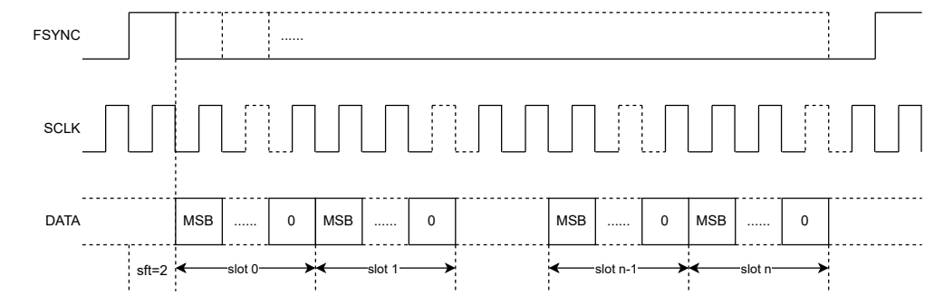
Figure 2-2 Timing Gen
Example 2: FSYNC = 1 x SCLK, SFT = 2 x 0.5 SCLK, falling edge receive data, rising edge send data
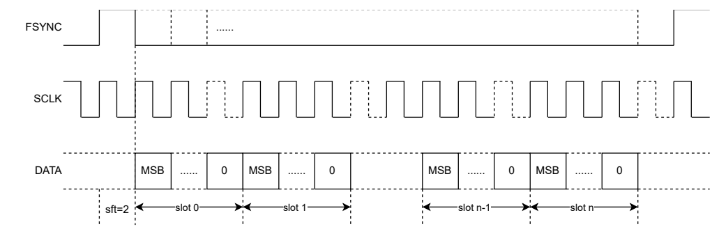
Figure 2-3 Timing Gen SCLK INV
Common formats listed below are all constructed from the timing shown in the above figures.
2.3.1.1.1 AUDIO_FMT_I2S
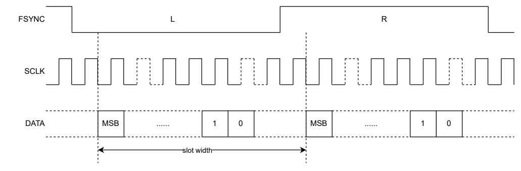
2.3.1.1.2 AUDIO_FMT_LEFT_J
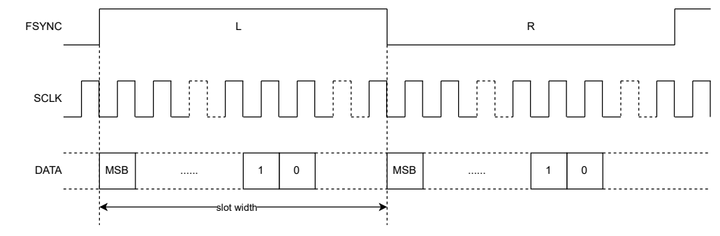
2.3.1.1.3 AUDIO_FMT_RIGHT_J
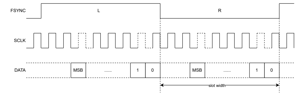
2.3.1.1.4 AUDIO_FMT_DSP_A
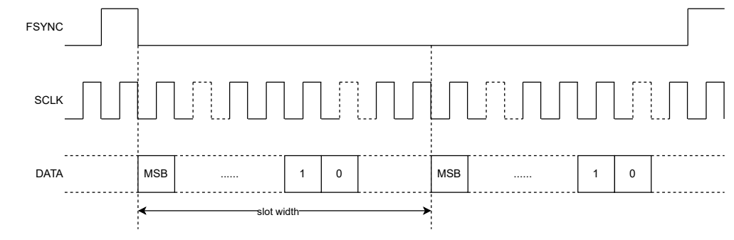
2.3.1.1.5 AUDIO_FMT_DSP_B
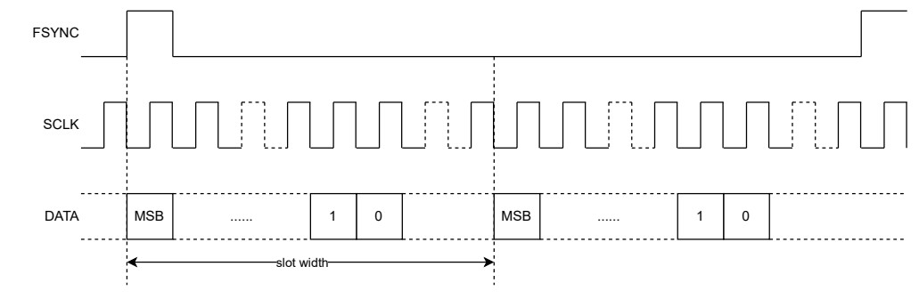
2.3.1.1.6 AUDIO_FMT_TDM_I2S
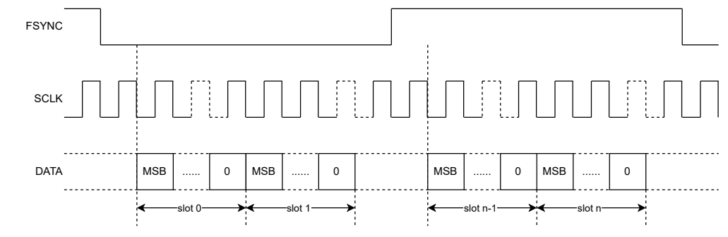
2.3.1.1.7 AUDIO_FMT_TDM_I2S_INV
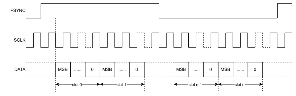
2.3.1.1.8 AUDIO_FMT_TDM_LEFT_J
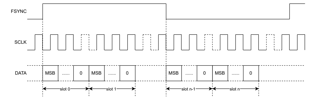
2.3.1.1.9 AUDIO_FMT_TDM_DSP_A
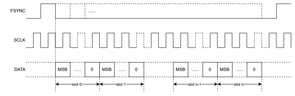
2.3.1.1.10 AUDIO_FMT_TDM_DSP_B
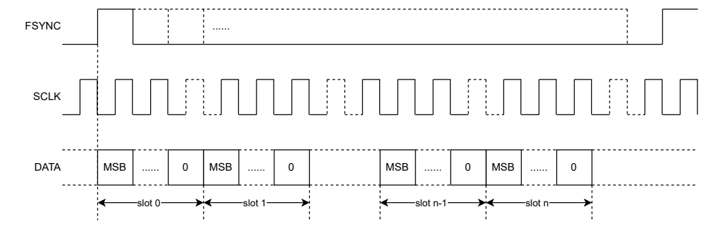
2.3.1.2 Multi Lanes
In Multi Lanes scenarios, the channel arrangement is interleaved, with a granularity of 2 CHs as a unit. For scenarios with more than 2 Lanes, if the peer data is output in Lane order, de-interleaving is required. You can directly call the API to handle it.
The following describes the channel arrangement relationship of Multi Lanes using TDM16 as an example. The same applies to other formats.
2.3.1.2.1 TDM16 x 1
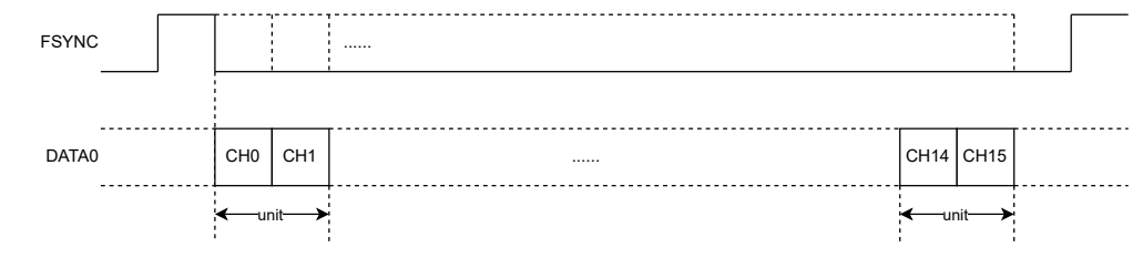
2.3.1.2.2 TDM16 x 2

2.3.1.2.3 TDM16 x 3

2.3.1.2.4 TDM16 x 4

2.3.1.2.5 Order vs Interleaved
The corresponding relationship when interfacing with an ordered format is described using TDM16 x 2. The same applies to others.
As shown in the figure, the signal transmitted from the peer is arranged sequentially on the Lane. SAI receives it in an interleaved manner. The received data arrangement is as shown in the figure and needs to be de- interleaved to output in an ordered format.

Figure 2-4 Order vs Interleaved
| CH0 | CH1 | CH2 | CH3 | CH4 | CH5 | CH6 | CH7 | CH8 | CH9 | CH10 | CH11 | CH12 | CH13 | CH14 | CH15 |
|---|---|---|---|---|---|---|---|---|---|---|---|---|---|---|---|
| CH16 | CH17 | CH18 | CH19 | CH20 | CH21 | CH22 | CH23 | CH24 | CH25 | CH26 | CH27 | CH28 | CH29 | CH30 | CH31 |

| CH0 | CH1 | CH16 | CH17 | CH2 | CH3 | CH18 | CH19 | CH4 | CH5 | CH20 | CH21 | CH6 | CH7 | CH22 | CH23 |
|---|---|---|---|---|---|---|---|---|---|---|---|---|---|---|---|
| CH8 | CH9 | CH24 | CH25 | CH10 | CH11 | CH26 | CH27 | CH12 | CH13 | CH28 | CH29 | CH14 | CH15 | CH30 | CH31 |
Figure 2-5 De-Interleaved
2.3.1.3 Multi SAI Combined
Supports merging multiple SAIs into one SAI for use, expanding Lanes capability.
Based on a one-master-multiple-slaves mechanism, the SoC internally provides clock signal sharing.
Only the master SAI provides the interface clock. Pay attention to hardware layout.
SAI V5 supports merging audio streams (previous versions merged audio streams via DMA)
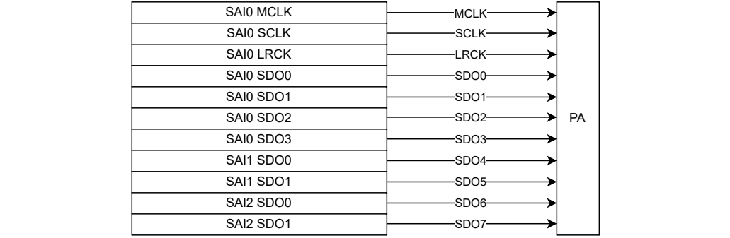
Example: SAI0 + SAI1 + SAI2 form I2S 8TX
2.3.1.4 Slot Mask
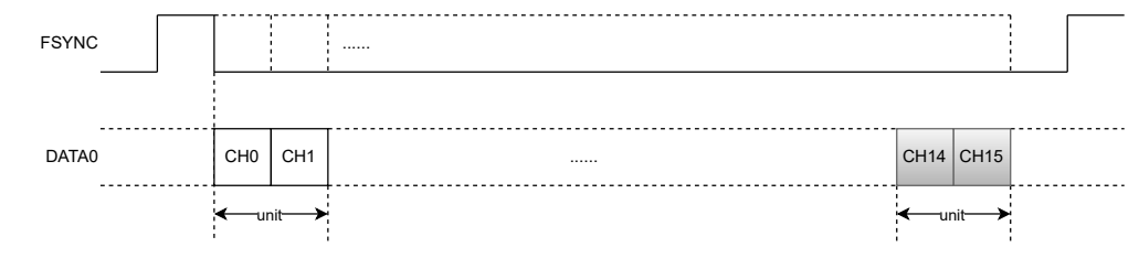
SAI supports slot mask. You can ignore data from the corresponding slot by configuring the mask bit.
Example 1: TDM16 x 1 with Mask last 2 slot
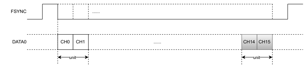
Example 2: TDM16 x 2 with Mask last 2 slot
Note:
The slot mask acts on all Lanes simultaneously, so be careful when using it in Multi Lanes scenarios.
2.3.1.5 slot width settings
| Property | Value | Description |
|---|---|---|
| rockchip,slot-width | int | Default slot width is 32bit |
Example: slot width is 16bits, typically used in bt scenarios, equivalent to the bclk-fs property of I2S.
&sai0 {
        rockchip,slot-width = <16>;
};
2.3.1.6 data line full mapping settings
Hardware can connect to any data line. Configure the corresponding properties to correct the channel order, or use path sel to select or check correctness.
| property | value | Description |
|---|---|---|
| rockchip,sai-tx-route | Default order: SDO0 | SDO1 | SDO2 | SDO3 | |
| rockchip,sai-rx-route | Default order: SDI0| SDI1 | SDI2 | SDI3 |
Example: Playback channel order is “SDO3 | SDO2 | SDO1 | SDO0”
&sai0 {
        rockchip,sai-tx-route = <3 2 1 0>;
};
2.3.1.7 multi lanes settings
This property is mainly used for Multiple Lanes TDM. It can also be selected or checked for correctness via lanes sel.
| property | value | Description |
|---|---|---|
| rockchip,tdm-tx-lanes | int | Default 1 lane |
| rockchip,tdm-rx-lanes | int | Default 1 lane |
Example: tdm-tx x 4, tdm-rx x 2
&sai0 {
        rockchip,tdm-tx-lanes = <4>;
        rockchip,tdm-rx-lanes = <2>;
};
2.3.1.8 wait time
This property is mainly used for the timeout mechanism in slave mode. When the peripheral clock is lost, the ASoC framework times out by default after 10s and returns. This property can be configured to shorten the waiting time and optimize the experience. It is recommended to set it greater than or equal to the buffer time.
| property | value | Description |
|---|---|---|
| rockchip,sai-tx-wait-time-ms | int | Default 10s |
| rockchip,sai-rx-wait-time-ms | int | Default 10s |
Example: buffer time 40ms, wait time 50ms
&sai0 {
        rockchip,sai-tx-wait-time-ms = <50>;
        rockchip,sai-rx-wait-time-ms = <50>;
};
2.3.1.9 mclkout / mclkin
mclk supports mclkout and mclkin functions, sharing pins. Combined with the sai master/slave mode, the usage scenarios are described. If the peripheral does not need mclk, the connection can be omitted.
| sai | mclk | Description |
|---|---|---|
| master | out | SoC provides clock to the peripheral |
| master | in | sai uses external mclkin clock, typical application: audio clock same source |
| slave | out | Peripheral works in master mode, mclk provided by SoC |
| slave | in | No application scenario |
Example: mclkout
rk817_codec: codec {
        #sound-dai-cells = <0>;
        compatible = "rockchip,rk817-codec";
        clocks = <&mclkout_sai0>;
        clock-names = "mclk";
        assigned-clocks = <&mclkout_sai0>;
        assigned-clock-rates = <12288000>;
        pinctrl-names = "default";
        pinctrl-0 = <&i2s0m0_mclk>;
        hp-volume = <20>;
        spk-volume = <3>;
        mic-in-differential;
        status = "okay";
};
Example: mclkin
&sai0 {
        assigned-clocks = <&cru CLK_SAI0>;
        assigned-clock-parents = <&mclkin_i2s0>;
        pinctrl-0 = <&sai0_sdi
                     &sai0_sdo
                     &sai0_lrck
                     &sai0_sclk
                     &sai0_mclk>;
};
&mclkin_sai0 {
        clock-frequency = <24576000>;
        status = "okay";
};
2.3.1.10 controls
You can easily view and set modes, protocols, functions, etc., via amixer or tinymix.
# amixer  -c 0 controls
numid=34,iface=MIXER,name='SAI2 Clk Auto Switch'
numid=5,iface=MIXER,name='SAI2 Receive Mono Slot Select'
numid=6,iface=MIXER,name='SAI2 Receive Mono Switch'
numid=29,iface=MIXER,name='SAI2 Receive PATH0 Source Select'
numid=28,iface=MIXER,name='SAI2 Receive PATH1 Source Select'
numid=27,iface=MIXER,name='SAI2 Receive PATH2 Source Select'
numid=26,iface=MIXER,name='SAI2 Receive PATH3 Source Select'
numid=4,iface=MIXER,name='SAI2 Receive SDIx Select'
numid=2,iface=MIXER,name='SAI2 Receive Start Mode Sel'
numid=11,iface=MIXER,name='SAI2 SDI0 Loopback I2S LR Channel Sel'
numid=15,iface=MIXER,name='SAI2 SDI0 Loopback I2S LR Switch'
numid=19,iface=MIXER,name='SAI2 SDI0 Loopback Src Select'
numid=23,iface=MIXER,name='SAI2 SDI0 Loopback Switch'
numid=10,iface=MIXER,name='SAI2 SDI1 Loopback I2S LR Channel Sel'
numid=14,iface=MIXER,name='SAI2 SDI1 Loopback I2S LR Switch'
numid=18,iface=MIXER,name='SAI2 SDI1 Loopback Src Select'
numid=22,iface=MIXER,name='SAI2 SDI1 Loopback Switch'
numid=9,iface=MIXER,name='SAI2 SDI2 Loopback I2S LR Channel Sel'
numid=13,iface=MIXER,name='SAI2 SDI2 Loopback I2S LR Switch'
numid=17,iface=MIXER,name='SAI2 SDI2 Loopback Src Select'
numid=21,iface=MIXER,name='SAI2 SDI2 Loopback Switch'
numid=8,iface=MIXER,name='SAI2 SDI3 Loopback I2S LR Channel Sel'
numid=12,iface=MIXER,name='SAI2 SDI3 Loopback I2S LR Switch'
numid=16,iface=MIXER,name='SAI2 SDI3 Loopback Src Select'
numid=20,iface=MIXER,name='SAI2 SDI3 Loopback Switch'
numid=25,iface=MIXER,name='SAI2 Sync In Switch'
numid=24,iface=MIXER,name='SAI2 Sync Out Switch'
numid=7,iface=MIXER,name='SAI2 Transmit Mono Switch'
numid=33,iface=MIXER,name='SAI2 Transmit SDO0 Source Select'
numid=32,iface=MIXER,name='SAI2 Transmit SDO1 Source Select'
numid=31,iface=MIXER,name='SAI2 Transmit SDO2 Source Select'
numid=30,iface=MIXER,name='SAI2 Transmit SDO3 Source Select'
numid=3,iface=MIXER,name='SAI2 Transmit SDOx Select'
numid=1,iface=MIXER,name='SAI2 Transmit Start Mode Sel'
numid=35,iface=PCM,name='SAI2 PCM Read Wait Time MS'
numid=36,iface=PCM,name='SAI2 PCM Write Wait Time MS'
2.3.1.10.1 path sel
sai transmits data in the order PATH0~3: when 1 lane is enabled, PATH0 is used; when 2 lanes are enabled, PATH0/1 are used; and so on.
PATHx and SDx are fully mapped. You can select SDIx / SDOx to route data, providing flexible hardware connections.
numid=29,iface=MIXER,name='SAI2 Receive PATH0 Source Select'
numid=28,iface=MIXER,name='SAI2 Receive PATH1 Source Select'
numid=27,iface=MIXER,name='SAI2 Receive PATH2 Source Select'
numid=26,iface=MIXER,name='SAI2 Receive PATH3 Source Select'
numid=33,iface=MIXER,name='SAI2 Transmit SDO0 Source Select'
numid=32,iface=MIXER,name='SAI2 Transmit SDO1 Source Select'
numid=31,iface=MIXER,name='SAI2 Transmit SDO2 Source Select'
numid=30,iface=MIXER,name='SAI2 Transmit SDO3 Source Select'
Example: SAI2 4CH I2S format data output from SDO2/3
# amixer cset iface=MIXER,name='SAI2 Transmit SDO2 Source Select' "From PATH0"
numid=31,iface=MIXER,name='SAI2 Transmit SDO2 Source Select'
  ; type=ENUMERATED,access=rw------,values=1,items=4
  ; Item #0 'From PATH0'
  ; Item #1 'From PATH1'
  ; Item #2 'From PATH2'
  ; Item #3 'From PATH3'
  : values=0
# amixer cset iface=MIXER,name='SAI2 Transmit SDO3 Source Select' "From PATH1"
numid=30,iface=MIXER,name='SAI2 Transmit SDO3 Source Select'
  ; type=ENUMERATED,access=rw------,values=1,items=4
  ; Item #0 'From PATH0'
  ; Item #1 'From PATH1'
  ; Item #2 'From PATH2'
  ; Item #3 'From PATH3'
  : values=1
Example: SAI2 2CH I2S format data input from SDI3
# amixer cset iface=MIXER,name='SAI2 Receive PATH0 Source Select' "From SDI3"
numid=29,iface=MIXER,name='SAI2 Receive PATH0 Source Select'
  ; type=ENUMERATED,access=rw------,values=1,items=4
  ; Item #0 'From SDI0'
  ; Item #1 'From SDI1'
  ; Item #2 'From SDI2'
  ; Item #3 'From SDI3'
  : values=3
2.3.1.10.2 lanes sel
Select the number of SDO and SDI lanes to use N lanes. The default is “Auto” mode. In I2S format, it is automatically enabled based on 2ch per lane. In TDM mode, only 1 lane will be used in this mode. When multiple lane TDM is needed, configure N lanes before the controller works.
numid=4,iface=MIXER,name='SAI2 Receive SDIx Select'
numid=3,iface=MIXER,name='SAI2 Transmit SDOx Select'
Example: TDM-TX: 2 lanes TDM-RX: 4 lanes
# amixer -c 0 cset iface=MIXER,name='SAI2 Transmit SDOx Select' "SDOx2"
numid=3,iface=MIXER,name='SAI2 Transmit SDOx Select'
  ; type=ENUMERATED,access=rw------,values=1,items=5
  ; Item #0 'Auto'
  ; Item #1 'SDOx1'
  ; Item #2 'SDOx2'
  ; Item #3 'SDOx3'
  ; Item #4 'SDOx4'
  : values=2
# amixer -c 0 cset iface=MIXER,name='SAI2 Receive SDIx Select' "SDIx4"
numid=4,iface=MIXER,name='SAI2 Receive SDIx Select'
  ; type=ENUMERATED,access=rw------,values=1,items=5
  ; Item #0 'Auto'
  ; Item #1 'SDIx1'
  ; Item #2 'SDIx2'
  ; Item #3 'SDIx3'
  ; Item #4 'SDIx4'
  : values=4
2.3.1.10.3 loopback sel
Supports digital loopback at the lane level. Select the source of SDIx to be from SDOx. No hardware connection is required.
numid=19,iface=MIXER,name='SAI2 SDI0 Loopback Src Select'
numid=23,iface=MIXER,name='SAI2 SDI0 Loopback Switch'
numid=18,iface=MIXER,name='SAI2 SDI1 Loopback Src Select'
numid=22,iface=MIXER,name='SAI2 SDI1 Loopback Switch'
numid=17,iface=MIXER,name='SAI2 SDI2 Loopback Src Select'
numid=21,iface=MIXER,name='SAI2 SDI2 Loopback Switch'
numid=16,iface=MIXER,name='SAI2 SDI3 Loopback Src Select'
numid=20,iface=MIXER,name='SAI2 SDI3 Loopback Switch'
Example: The loopback signal for SDI1 comes from SDO3
# amixer -c 0 cset iface=MIXER,name='SAI2 SDI0 Loopback Src Select' "From SDO3"
numid=19,iface=MIXER,name='SAI2 SDI0 Loopback Src Select'
  ; type=ENUMERATED,access=rw------,values=1,items=4
  ; Item #0 'From SDO0'
  ; Item #1 'From SDO1'
  ; Item #2 'From SDO2'
  ; Item #3 'From SDO3'
  : values=3
Starting from SAI-V3, i2s 1mic + 1lp loopback combination is supported. Chip support refers to the SAI Support List.
numid=11,iface=MIXER,name='SAI2 SDI0 Loopback I2S LR Channel Sel'
numid=15,iface=MIXER,name='SAI2 SDI0 Loopback I2S LR Switch'
numid=10,iface=MIXER,name='SAI2 SDI1 Loopback I2S LR Channel Sel'
numid=14,iface=MIXER,name='SAI2 SDI1 Loopback I2S LR Switch'
numid=9,iface=MIXER,name='SAI2 SDI2 Loopback I2S LR Channel Sel'
numid=13,iface=MIXER,name='SAI2 SDI2 Loopback I2S LR Switch'
numid=8,iface=MIXER,name='SAI2 SDI3 Loopback I2S LR Channel Sel'
numid=12,iface=MIXER,name='SAI2 SDI3 Loopback I2S LR Switch'
Example: I2S left channel MIC data + right channel loopback data
# amixer -c 0 cset iface=MIXER,name='SAI2 SDI0 Loopback I2S LR Channel Sel' "L:M IC R:LP"
numid=11,iface=MIXER,name='SAI2 SDI0 Loopback I2S LR Channel Sel'
  ; type=ENUMERATED,access=rw------,values=1,items=2
  ; Item #0 'L:MIC R:LP'
  ; Item #1 'L:LP R:MIC'
  : values=0
2.3.2 ASRC
Currently uses the multicodec driver to integrate ASRC into the audio stream.
2.3.2.1 Sound Card Configuration
- Enable CONFIG
CONFIG_SND_SOC_ROCKCHIP_ASRC=y
- After the sound card is successfully configured, two devices will be generated. Take sound card 0 as an example:
| Sound Card Device | Description |
|---|---|
| hw:0,0 | without asrc |
| hw:0,1 | with asrc |
Example 1: SAI(Slave) -> ASRC -> MEM
sai0-asrc-sound {
    compatible = "rockchip,multicodecs-card";
    rockchip,card-name = "rockchip,sai0-asrc";
    rockchip,mclk-fs = <256>;
    rockchip,format = "i2s";
    rockchip,cpu = <&sai0>;
    rockchip,asrc = <&asrc0>;
    rockchip,codec = <&dummy_codec>;
    rockchip,bitclock-master = <&dummy_codec>;
    rockchip,frame-master = <&dummy_codec>;
    rockchip,audio-routing =
        "Dummy Playback", "SAI0 Playback",
        "SAI0 Capture", "Dummy Capture",
        "SAI0 Playback", "ASRC0 Playback",
        "ASRC0 Capture", "SAI0 Capture";
};
Example 2: SPDIFRX -> ASRC -> MEM
spdifrx0-asrc-sound {
    compatible = "rockchip,multicodecs-card";
    rockchip,card-name = "spdifrx0-asrc";
    rockchip,cpu = <&spdif_rx0>;
    rockchip,asrc = <&asrc0>;
    rockchip,codec = <&dummy_codec>;
    rockchip,audio-routing =
        "Dummy Capture", "Dummy Capture",
        "ASRC0 Capture", "SPDIF_RX0 Capture";
};
2.3.2.2 Resample Settings
Set the resample clock to 48K as follows:
amixer -c 0 sset 'ASRC0 SET RESAMPLE RATE' 48000
2.3.2.3 Clock Source Settings
Set the SRC/DST tracking clock source for ASRC. SRC/DST can be any combination of local clock and external clock.
Example 1: ASRC’s SRC clock comes from SAI0, DST clock comes from ASRC. ASRC handles the asynchronous between SAI0 and the local clock.
amixer -c 0 sset 'ASRC0 RX LINK DAI Select' 'sai0'
amixer -c 0 sset 'ASRC0 TX LINK DAI Select' 'asrc0'
Example 2: ASRC’s SRC clock comes from SAI0, DST clock comes from SAI2. ASRC handles the asynchronous between SAI0 and SAI2.
amixer -c 0 sset 'ASRC0 RX LINK DAI Select' 'sai0'
amixer -c 0 sset 'ASRC0 TX LINK DAI Select' 'sai2'
2.3.2.4 Recording
amixer -c 0 sset 'ASRC0 SET RESAMPLE RATE' 48000
amixer -c 0 sset 'ASRC0 RX LINK DAI Select' 'sai0'
amixer -c 0 sset 'ASRC0 TX LINK DAI Select' 'asrc0'
arecord -D hw:0,1 --period-size=1024 --buffer-size=4096 -r 48000 -c 2 -f s16_le r.wav
2.3.2.5 Playback
amixer -c 0 sset 'ASRC0 SET RESAMPLE RATE' 48000
amixer -c 0 sset 'ASRC0 RX LINK DAI Select' 'asrc0'
amixer -c 0 sset 'ASRC0 TX LINK DAI Select' 'sai0'
aplay -D hw:0,1 --period-size=1024 --buffer-size=4096 r.wav
2.3.3 I2S
2.3.3.1 Protocol format configuration
Protocol format configuration is achieved by parsing the DTS through the Machine Driver, and then invoking the API set_fmt to set the protocol format of the controller. For Simple Card, please refer to the Simple Card section.
2.3.3.2 Master / Slave configuration
Master / slave configuration is achieved by parsing the DTS through the Machine Driver, and then invoking the API set_fmt to set the protocol format of the controller. For Simple Card, please refer to the Simple Card section.
2.3.3.3 Clock phase inversion configuration
Clock phase inversion configuration is achieved by parsing the DTS through the Machine Driver, and then invoking the API set_fmt to set the protocol format of the controller. For Simple Card, please refer to the Simple Card section.
2.3.3.4 bclk-fs configuration
| Property | Value | Description |
|---|---|---|
| rockchip,bclk-fs | int | The default value for bclk is 64 times the sampling rate |
Example: bclk is 32 times the sampling rate
&i2s0 {
        rockchip,bclk-fs = <32>;
};
2.3.3.5 High-precision clock configuration
| Property | Value | Description |
|---|---|---|
| rockchip,mclk-calibrate | boolean | Support high-precision clock and clock compensation, please refer to audio clock compensation |
2.3.3.6 wait time
This property is mainly used for the timeout mechanism in slave mode. When the peripheral clock is lost, the ASoC framework times out by default after 10s and returns. This property can be configured to shorten the waiting time and optimize the experience. It is recommended to set it greater than or equal to the buffer time.
| property | value | Description |
|---|---|---|
| rockchip,i2s-tx-wait-time-ms | int | Default 10s |
| rockchip,i2s-rx-wait-time-ms | int | Default 10s |
Example: buffer time 40ms, wait time 50ms
&i2s0 {
        rockchip,i2s-tx-wait-time-ms = <50>;
        rockchip,i2s-rx-wait-time-ms = <50>;
};
2.3.3.7 Others
| Property | Value | Description |
|---|---|---|
| rockchip,no-dmaengine | boolean | Used for Multi-DAI, please refer to Combo DAI Driver |
| rockchip,playback-only | boolean | Only supports playback function |
| rockchip,capture-only | boolean | Only supports capture function |
2.3.3.8 mclkout / mclkin
mclk supports mclkout and mclkin functions, sharing pins. Combined with the i2s master/slave mode, the usage scenarios are described. If the peripheral does not need mclk, the connection can be omitted.
| i2s | mclk | Description |
|---|---|---|
| master | out | SoC provides clock to the peripheral |
| master | in | i2s uses external mclkin clock, typical application: audio clock same source |
| slave | out | Peripheral works in master mode, mclk provided by SoC |
| slave | in | No application scenario |
Example: mclkout
rk817_codec: codec {
        #sound-dai-cells = <0>;
        compatible = "rockchip,rk817-codec";
        clocks = <&mclkout_i2s0>;
        clock-names = "mclk";
        assigned-clocks = <&mclkout_i2s0>;
        assigned-clock-rates = <12288000>;
        pinctrl-names = "default";
        pinctrl-0 = <&i2s0m0_mclk>;
        hp-volume = <20>;
        spk-volume = <3>;
        mic-in-differential;
        status = "okay";
};
Example: mclkin
&i2s3_2ch {
        assigned-clocks = <&cru CLK_I2S3_2CH>;
        assigned-clock-parents = <&mclkin_i2s3>;
        pinctrl-0 = <&i2s3_sdi
                     &i2s3_sdo
                     &i2s3_lrck
                     &i2s3_sclk
                     &i2s3_mclk>;
};
&mclkin_i2s3 {
        clock-frequency = <24576000>;
        status = "okay";
};
For more details, please refer to: kernel/Documentation/devicetree/bindings/sound/rockchip-i2s.txt
2.3.4 I2S-TDM
In addition to the functions supported by the I2S controller, the I2S-TDM controller also adds support for the following features
2.3.4.1 TX/RX Clock Sharing configuration
| Property | Value | Description |
|---|---|---|
| rockchip,clk-trcm | 0 | TX/RX are logically independent and use their own clocks, and there are two sets of clocks on IO |
| rockchip,clk-trcm | 1 | TX/RX are logically synchronized and share the clock of TX. There is only the clock of TX on the IO |
| rockchip,clk-trcm | 2 | TX/RX are logically synchronized and share the clock of RX. There is only the clock of RX on the IO |
Example: Set to share the TX clock mode.
&i2s0 {
        rockchip,clk-trcm = <1>;
};
2.3.4.2 Data Lane Remapping configuration
The hardware design can connect to any SDOx/SDIx, and the software can remap the relationship between the PATHx and SDOx/SDIx.
| property | value | Description |
|---|---|---|
| rockchip,i2s-tx-route | <int int int int> | Default order: SDO0 | SDO1 | SDO2 | SDO3 |
| rockchip,i2s-rx-route | <int int int int> | Default order: SDI0| SDI1 | SDI2 | SDI3 |
Example: Playback channel order is arranged as “SDO3 | SDO2 | SDO1 | SDO0”.
&i2s0 {
        rockchip,i2s-tx-route = <3 2 1 0>;
};
2.3.4.3 TDM half-frame mode configuration
| property | value | Description |
|---|---|---|
| rockchip,tdm-fsync-half-frame | boolean | In TDM I2S mode, the frame clock supports both half-frame and long-frame formats, long-frame format default. |
Example: Half-frame format
&i2s0 {
        rockchip,tdm-fsync-half-frame;
};
2.3.4.4 TDM Slots configuration
The driver has implemented the API set_tdm_slot , and the machine driver parses the DTS properties and calls the API set_tdm_slot to set the corresponding slots of the controller. For Simple Card, please refer to the section Simple Card.
2.3.4.5 mclkout / mclkin
mclk supports mclkout and mclkin functions, sharing pins. Combined with the i2stdm master/slave mode, the usage scenarios are described. If the peripheral does not need mclk, the connection can be omitted.
| i2stdm | mclk | Description |
|---|---|---|
| master | out | SoC provides clock to the peripheral |
| master | in | i2stdm uses external mclkin clock, typical application: audio clock same source |
| slave | out | Peripheral works in master mode, mclk provided by SoC |
| slave | in | No application scenario |
Example: mclkout
rk817_codec: codec {
        #sound-dai-cells = <0>;
        compatible = "rockchip,rk817-codec";
        clocks = <&mclkout_i2s0>;
        clock-names = "mclk";
        assigned-clocks = <&mclkout_i2s0>;
        assigned-clock-rates = <12288000>;
        pinctrl-names = "default";
        pinctrl-0 = <&i2s0m0_mclk>;
        hp-volume = <20>;
        spk-volume = <3>;
        mic-in-differential;
        status = "okay";
};
Example: mclkin
&i2s0_8ch {
        assigned-clocks = <&cru CLK_I2S0_8CH_TX>, <&cru CLK_I2S0_8CH_RX>;
        assigned-clock-parents = <&mclkin_i2s0>, <&mclkin_i2s0>;
        pinctrl-0 = <&i2s0_sdi0
                     &i2s0_sdo0
                     &i2s0_lrck
                     &i2s0_sclk
                     &i2s0_mclk>;
};
&mclkin_i2s0 {
        clock-frequency = <24576000>;
        status = "okay";
};
For more details, please refer to: kernel/Documentation/devicetree/bindings/sound/rockchip,i2s-tdm.txt
2.3.5 PDM
2.3.5.1 Data Lane Remapping configuration
The hardware design can connect to any SDIx, and the software can remap the relationship between the PATHx and SDIx.
| property | value | Description |
|---|---|---|
| rockchip,path-map | <int int int int> | Default order: SDI0 | SDI1 | SDI2 | SDI3 |
Example: Recording channel order arranged as “SDI3 | SDI2 | SDI1 | SDI0”
&pdm_8ch {
        rockchip,path-map = <3 2 1 0>;
};
2.3.5.2 High-precision clock configuration
| Property | Value | Description |
|---|---|---|
| rockchip,mclk-calibrate | boolean | Support high-precision clock and clock compensation, please refer to audio clock compensation |
2.3.5.3 Others
| Property | Value | Description |
|---|---|---|
| rockchip,no-dmaengine | boolean | Used for Multi-DAI, please refer to Combo DAI Driver |
For more details, please refer to: kernel/Documentation/devicetree/bindings/sound/rockchip,pdm.txt
2.3.6 DCODEC
2.3.6.1 Clock Synchronization Mode
| Property | Value | Description |
|---|---|---|
| rockchip,clk-sync-mode | boolean | By default, it operates in asynchronous mode, which means the ADC/DAC clocks are independent. |
Example: Set to clock synchronization mode, share ADC clock
&dig_acodec {
        rockchip,clk-sync-mode;
};
2.3.6.2 DSM output Mode
| Property | Value | Description |
|---|---|---|
| rockchip,pwm-output-mode | boolean | Drive PA directly with a RC circult |
Example: Set to DSM PWM output mode and switch IOMUX to PWM differential output
&dig_acodec {
        rockchip,pwm-output-mode;
        pinctrl-names = "default";
        pinctrl-0 = <&audiopwmoutdiff_pins>;
};
The hardware reference is shown in Figure 2-2:
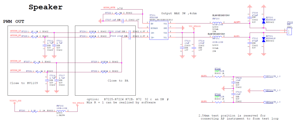
Figure 2-6 DSM PWM OUT Reference
For more details, please refer to:
kernel/Documentation/devicetree/bindings/sound/rockchip,codec-digital.txt
2.3.7 VAD
2.3.7.1 Audio source configuration
| Property | Value | Description |
|---|---|---|
| rockchip,audio-src | phandle | Set the audio source for speech detection |
The audio source used for voice detection comes from DAI, and the audio sources supported by different chips are different, as shown in the following table:
| SoC | Audio Source |
|---|---|
| RK1808 | I2S0, I2S1, PDM |
| RK3308 | I2S_8CH_0, I2S_8CH_1, I2S_8CH_2, I2S_8CH_3, PDM_8CH |
| RK3568/RK3566 | I2S1_8CH, I2S2_2CH, I2S3_2CH |
Example: VAD use PDM_8CH as audio source on RK3308
&vad {
        rockchip,audio-src = <&pdm_8ch>;
};
2.3.7.2 Detect channel configuration
| Property | Value | Description |
|---|---|---|
| rockchip,det-channel | int | Set the channel used for detection, default channel 0 |
Example: VAD uses channel 2 as detection channel on RK3308
&vad {
        rockchip,det-channel = <2>;
};
2.3.7.3 Data storage mode configuration
| Property | Value | Description |
|---|---|---|
| rockchip,mode | 0 | The audio data is buffered only after the VAD detects a speech signal. |
| rockchip,mode | 1 | Once the VAD is enabled, the audio data is immediately buffered. |
| rockchip,mode | 2 | Do not buffer any audio data. |
Example: VAD uses mode 1 on RK3308
&vad {
        rockchip,mode = <1>;
};
Note:
In order to ensure that the post-ASR application can obtain the complete audio data, it is recommended to use Mode 1. The buffered data is stored in the circular buffer of the SRAM. After the VAD wakes up the system, the audio data buffered on the SRAM is merged into the audio stream, and this part of the data processing is transparent to the application.
2.3.7.4 Buffer size configuration
| Property | Value | Description |
|---|---|---|
| rockchip,buffer-time-ms | int | Set the VAD buffer size, the size is equal to: sample rate * bit width * channel * time. |
Example: Set the buffer time to 100ms, which is 204800 bytes under the condition of 16k 16bits 8ch.
&vad {
        rockchip,buffer-time-ms = <100>;
};
Note: Increasing the buffer size will increase the latency of the ASR application accordingly. Moreover, the system SRAM is limited, so adjust it with caution. The adjustment strategy is to “ensure data integrity”, that is, the buffer size should cover the “wake-up -> application takeover” time. If this part of the time is too long, please optimize it.
For more details, please refer to: kernel/Documentation/devicetree/bindings/sound/rockchip,vad.txt
2.4 Combo DAI Driver Development
2.4.1 Sub Dai configuration
| Property | Value | Description |
|---|---|---|
| dais | <phandle>… | Sub-DAI is used to combine with other Sub-DAIs to form a combo DAI. The “rockchip,no-dmaengine” property is used for Sub-DAI to remove the associated DMA engine and then unify the registration and binding by the Combo DAI framework. |
Example: Combine i2s_8ch_2 and pdm_8ch into Combo DAI
&i2s_8ch_2 {
        status = "okay";
        rockchip,no-dmaengine;
};
&pdm_8ch {
        status = "okay";
        rockchip,no-dmaengine;
};
&multi-dais {
        dais = <&i2s_8ch_2>, <&pdm_8ch>;
};
2.4.2 Channel Mapping configuration
| Property | Value | Description |
|---|---|---|
| capture,channel-mapping | <int …> | The number of capture channels for each sub DAI used for combination |
| playback,channel-mapping | <int …> | The number of playback channels for each sub DAI used for combination |
Example: Stereo playback and 8-channel capture (6-channel microphone + 2-channel loopback).
&multi-dais {
        dais = <&i2s_8ch_2>, <&pdm_8ch>;
        playback,channel-mapping = <2 0>;
        capture,channel-mapping = <2 6>;
};
2.4.3 Master / Slave configuration
| Property | Value | Description |
|---|---|---|
| bitclock-master | <int …> | Set the device that provides the bit clock, with 1 indicating that the device provides the clock, i.e., the master. |
| frame-master | <int …> | Set the device that provides the frame clock, with 1 indicating that the device provides the clock, i.e., the master. |
Example 1: Combining i2s_8ch_2 and pdm_8ch to form an 8-channel capture sound card (loopback + microphone array). i2s_8ch_2 can be configured as a master/slave mode, and in this example, it is set as the master while pdm only supports the master mode.
&multi-dais {
        dais = <&i2s_8ch_2>, <&pdm_8ch>;
        capture,channel-mapping = <2 6>;
        playback,channel-mapping = <2 0>;
        bitclock-master = <1 1>;
        frame-master = <1 1>;
};
Example 2: Combining two I2S to form 16 channels, one as master and one as slave. The external hardware needs to connect the DAI that provides the clock to each slave DAI.
&multi-dais {
        dais = <&i2s_8ch_0>, <&i2s_8ch_1>;
        capture,channel-mapping = <8 8>;
        playback,channel-mapping = <8 8>;
        bitclock-master = <1 0>;
        frame-master = <1 0>;
};
Example 3: Combining two I2S interfaces to form 16 channels, both set to slave mode, and the the clock is provided by the codec which act as master.
&multi-dais {
        dais = <&i2s_8ch_0>, <&i2s_8ch_1>;
        capture,channel-mapping = <8 8>;
        playback,channel-mapping = <8 8>;
        bitclock-master = <0 0>;
        frame-master = <0 0>;
};
2.4.4 Clock phase inversion configuration
| Property | Value | Description |
|---|---|---|
| bitclock-inversion | <int …> | 1 indicates inverted bit clock |
| frame-inversion | <int …> | 1 indicates inverted frame clock |
Example: Invert the clocks of all sub-DAIs.
&multi-dais {
        dais = <&i2s_8ch_0>, <&i2s_8ch_1>;
        bitclock-inversion = <1 1>;
        frame-inversion = <1 1>;
};
2.4.5 Examples
Example 1: RK3308 PDM array microphone + stereo capture + stereo playback + VAD voice detection
multi_dais: multi-dais {
        status = "okay";
        compatible = "rockchip,multi-dais";
        dais = <&i2s_8ch_2>, <&pdm_8ch>;
        capture,channel-mapping = <2 6>;
        playback,channel-mapping = <2 0>;
        bitclock-master = <1 1>;
        frame-master = <1 1>;
        bitclock-inversion = <0 0>;
        frame-inversion = <0 0>;
        rockchip,grf = <&grf>;
};
&i2s_8ch_2 {
        status = "okay";
        rockchip,no-dmaengine;
};
&pdm_8ch {
        status = "okay";
        rockchip,no-dmaengine;
};
vad-sound {
        status = "okay";
        compatible = "rockchip,multicodecs-card";
        rockchip,card-name = "rockchip,rk3308-vad";
        rockchip,cpu = <&multi_dais>;
        rockchip,codec = <&acodec>, <&vad>;
};
Example 2: RK3308 SoundBar I2S_8CH_0 + I2S_8CH_1 combined for 16-channel output
&i2s_8ch_0 {
        #sound-dai-cells = <0>;
        rockchip,no-dmaengine;
};
&i2s_8ch_1 {
        #sound-dai-cells = <0>;
        rockchip,no-dmaengine;
        pinctrl-names = "default";
        pinctrl-0 = <&i2s_8ch_1_m0_sdo0
                     &i2s_8ch_1_m0_sdo1_sdi3
                     &i2s_8ch_1_m0_sdo2_sdi2
                     &i2s_8ch_1_m0_sdo3_sdi1
                     &i2s_8ch_1_m0_sdi0>;
};
i2s_16ch_dais: i2s-16ch-dais {
        compatible = "rockchip,rk3308-multi-dais", "rockchip,multi-dais";
        dais = <&i2s_8ch_0>, <&i2s_8ch_1>;
        capture,channel-mapping = <8 8>;
        playback,channel-mapping = <8 8>;
        bitclock-master = <1 0>;
        frame-master = <1 0>;
        rockchip,grf = <&grf>;
};
For more details, please refer to: kernel/Documentation/devicetree/bindings/sound/rockchip,multidais.txt
2.5 CODEC Driver Development
Please refer to: Linux Sound Subsystem Documentation
2.6 Machine Driver Development
The main purpose of this section is to describe the steps for adding a sound card with practical examples.
2.6.1 Simple Card Driver
Simple Card is a general-purpose machine driver for ASoC which can be adapted to most standard sound cards.
2.6.1.1 Protocol Format configuration
| Property | Value | Description |
|---|---|---|
| simple-audio-card,format | string | Set the protocol format |
| Format | Description |
|---|---|
| i2s | i2s standard format |
| right_j | i2s right-justified format |
| left_j | i2s left-justified format |
| dsp_a | pcm delay 1 bit |
| dsp_b | pcm no delay |
| pdm | pdm format |
Example: set to i2s left-justified format
audiopwmout_diff: audiopwmout-diff {
        compatible = "simple-audio-card";
        ....
        simple-audio-card,format = "left_j";
        simple-audio-card,cpu {
                sound-dai = <&i2s3_2ch>;
        };
        master: simple-audio-card,codec {
                sound-dai = <&dig_acodec>;
        };
};
2.6.1.2 mclk-fs configuration
| Property | Value | Description |
|---|---|---|
| simple-audio-card,mclk-fs | int | By default, mclk is 256 times the sample rate |
Example: mclk is 512 times the sample rate.
audiopwmout_diff: audiopwmout-diff {
        compatible = "simple-audio-card";
        ....
        simple-audio-card,mclk-fs = <512>;
        simple-audio-card,cpu {
                sound-dai = <&i2s3_2ch>;
        };
        master: simple-audio-card,codec {
                sound-dai = <&dig_acodec>;
        };
};
2.6.1.3 Master / Slave configuration
| Property | Value | Description |
|---|---|---|
| simple-audio-card,bitclock-master | phandle | Set the device that provides the bit clock, by default DAI provides the clock |
| simple-audio-card,frame-master | phandle | Set the device that provides the frame clock, by default DAI provides the clock |
Example: DAI acts as slave mode, CODEC acts as master mode
audiopwmout_diff: audiopwmout-diff {
        compatible = "simple-audio-card";
        ....
        simple-audio-card,bitclock-master = <&master>;
        simple-audio-card,frame-master = <&master>;
        simple-audio-card,cpu {
                sound-dai = <&i2s3_2ch>;
        };
        master: simple-audio-card,codec {
                sound-dai = <&dig_acodec>;
        };
};
2.6.1.4 Clock phase inversion configuration
| Property | Value | Description |
|---|---|---|
| simple-audio-card,bitclock-inversion | boolean | Inverted bit clock |
| simple-audio-card,frame-inversion | boolean | Inverted frame clock |
Example: bclk and lrck are both inverted.
audiopwmout_diff: audiopwmout-diff {
        compatible = "simple-audio-card";
        ...
        simple-audio-card,bitclock-inversion;
        simple-audio-card,frame-inversion;
        simple-audio-card,cpu {
                sound-dai = <&i2s3_2ch>;
        };
        simple-audio-card,codec {
                sound-dai = <&dig_acodec>;
        };
};
2.6.1.5 TDM slots configuration
| Property | Value | Description |
|---|---|---|
| dai-tdm-slot-num | int | Set the number of slots |
| dai-tdm-slot-width | int | Set the bit width of the slot |
Example: slot bit width is 32 bits, 8 slots
i2s-dmic-array {
        compatible = "simple-audio-card";
        ...
        simple-audio-card,mclk-fs = <256>;
        simple-audio-card,cpu {
                sound-dai = <&i2s_8ch_0>;
                dai-tdm-slot-num = <8>;
                dai-tdm-slot-width = <32>;
        };
        simple-audio-card,codec {
                sound-dai = <&dummy_codec>;
        };
};
Note: mclk-fs equals to [ slot num ] * [ slot-width ], or an even multiple of it.
For more details, please refer to: kernel/Documentation/devicetree/bindings/sound/simple-card.txt
2.6.1.6 Example of Adding a Sound Card
- Port or write a codec driver.
sound/soc/codecs/Kconfig
sound/soc/codecs/Makefile
sound/soc/codecs/tas571x.c
sound/soc/codecs/tas571x.h
- Enable CONFIG
CONFIG_SND_SIMPLE_CARD
CONFIG_SND_SOC_ROCKCHIP_I2S
CONFIG_SND_SOC_ROCKCHIP_I2S_TDM
CONFIG_SND_SOC_TAS571X
- Add DTS sound card node
Enable the corresponding i2s node according to the hardware connection
&i2s_8ch_1 {
        status = "okay";
        #sound-dai-cells = <0>;
        pinctrl-names = "default";
        pinctrl-0 = <&i2s_8ch_1_m0_sclktx
                     &i2s_8ch_1_m0_lrcktx
                     &i2s_8ch_1_m0_sdo0
                     &i2s_8ch_1_m0_mclk>;
};
Add the codec node under the corresponding I2C or SPI according to the hardware connection.
&i2c1 {
        clock-frequency = <400000>;
        status = "okay";
        tas5731: tas5731@1a {
                #sound-dai-cells = <0>;
                compatible = "ti,tas5731";
                reg = <0x1a>;
                clocks = <&cru SCLK_I2S1_8CH_TX_OUT>;
                clock-names = "mclk";
                pinctrl-names = "default";
                pinctrl-0 = <&i2s_8ch_1_m0_mclk>;
                pdn-gpios = <&gpio0 RK_PA5 GPIO_ACTIVE_LOW>;
                reset-gpios = <&gpio1 RK_PA1 GPIO_ACTIVE_LOW>;
        };
};
Add and enable sound card node
tas5731_sound: tas5731-sound {
        status = "okay";
        compatible = "simple-audio-card";
        simple-audio-card,format = "i2s";
        simple-audio-card,name = "rockchip,tas5731";
        simple-audio-card,mclk-fs = <256>;
        simple-audio-card,cpu {
                sound-dai = <&i2s_8ch_1>;
        };
        simple-audio-card,codec {
                sound-dai = <&tas5731>;
        };
};
Confirm that the sound card has been created successfully
# cat /proc/asound/cards
 0 [rockchiptas5731]: rockchip_tas5731 - rockchip,tas5731
Note:
The mclk follows the principle of “who uses, who applies”. When the codec needs to use an external mclk, the driver needs to apply for and manage the mclk. In this example, the codec mclk comes from the RK3308’s SCLK_I2S1_8CH_TX_OUT.
2.6.2 Multi Codecs Machine Driver
When Simple Card does not meet the requirements, it is necessary to write the corresponding Machine Driver. This section introduces RK’s Multi Codecs Machine Driver, which is used in scenarios where one DAI corresponds to multiple CODECs or a Combo DAI corresponds to multiple CODECs, as shown in Figure 2-3:
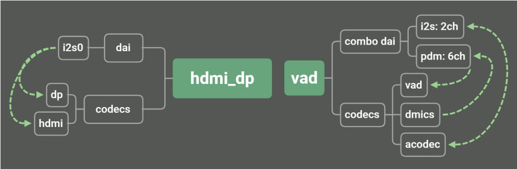
Figure 2-3 Multi Codecs Machine Driver
2.6.2.1 dai / codec configuration
| Property | Value | Description |
|---|---|---|
| rockchip,cpu | phandle | set the dai device |
| rockchip,codec | phandle… | Set the associated codecs |
Example: i2s0_8ch applied to both codec and vad
&sound {
        compatible = "rockchip,multicodecs-card";
        rockchip,cpu = <&i2s0_8ch>;
        rockchip,codec = <&codec>, <&vad>;
};
2.6.2.2 Protocol Format configuration
| Property | Value | Description |
|---|---|---|
| rockchip,format | string | set protocol format |
| Format | Description |
|---|---|
| i2s | i2s standard format |
| right_j | i2s right-justifiedformat |
| left_j | i2s left-justified format |
| dsp_a | pcm delay 1 bit |
| dsp_b | pcm no delay |
| pdm | pdm |
Example: Set to i2s left-justified format
&sound {
        rockchip,format = "left_j";
};
2.6.2.3 mclk-fs configuration
| Property | Value | Description |
|---|---|---|
| rockchip,mclk-fs | int | By default, mclk is 256 times the sample rate |
Example: mclk is 512 times the sample rate
&sound {
        rockchip,mclk-fs = <512>;
};
2.6.2.4 Master / Slave configuration
| Property | Value | Description |
|---|---|---|
| rockchip,frame-master | phandle | Set the device that provides the bit clock, by default DAI provides the clock |
| rockchip,bitclock-master | phandle | Set the device that provides the frame clock, by default DAI provides the clock |
Example: DAI acts as slave mode, CODEC acts as master mode
&sound {
        compatible = "rockchip,multicodecs-card";
        rockchip,frame-master = <&codec>;
        rockchip,bitclock-master = <&codec>;
        rockchip,cpu = <&i2s0_8ch>;
        rockchip,codec = <&codec>, <&vad>;
};
2.6.2.5 Clock phase inversion configuration
| Property | Value | Description |
|---|---|---|
| rockchip,bitclock-inversion | boolean | Inverted bit clock |
| rockchip,frame-inversion | boolean | Inverted frame clock |
Example: bclk and lrck are both inverted
&sound {
        compatible = "rockchip,multicodecs-card";
        rockchip,bitclock-inversion;
        rockchip,frame-inversion;
        rockchip,cpu = <&i2s0_8ch>;
        rockchip,codec = <&codec>, <&vad>;
};
2.6.2.6 wait-card-locked configuration
| Property | Value | Description |
|---|---|---|
| rockchip,wait-card-locked | int | Wait for a specific soundcard ID to register before registering, ensuring the current soundcard’s ID is after the specified ID |
Example: Hope the current bluetooth-sound registers as card1, need card0 to register before the current card registers.
bluetooth_sound: bluetooth-sound {
    status = "disabled";
    compatible = "rockchip,multicodecs-card";
    rockchip,card-name = "rockchip,rk3308-pcm";
    rockchip,mclk-fs = <128>;
    rockchip,cpu = <&i2s_2ch_0>;
    rockchip,codec = <&dummy_codec>;
    rockchip,format = "dsp_b";
    rockchip,bitclock-inversion = <0>;
    rockchip,wait-card-locked = <0>;
};
2.6.2.7 Others
| Property | Value | Description |
|---|---|---|
| hp-det-gpio | phandle | Headphone detection pin |
| spk-con-gpio | phandle | Amplifier speaker control pin |
| hp-con-gpio | phandle | Headphone control pin |
| io-channels | phandle | adc detection channel for distinguish 3/4-pole headphones |
| poll-interval | int | adc polling time interval. Default 100 ms |
| keyup-threshold-microvolt | int | adc button voltage |
| play-pause-key | phandle | Play pause key |
| rockchip,audio-routing | string | Sound card routing |
Example:
ADC3 used to distinguish 3/4-pole headphones, and also for play/pause buttons on the headphone cable.
Headphone corresponds to es8388’s LROUT1, controlled by Headphone Power gpio1_d2.
Speaker corresponds to es8388’s LROUT2, controlled by Speaker Power gpio1_d3.
LINPUT corresponds to es8388’s Main Mic, RINPUT corresponds to Headset Mic.
es8388_sound: es8388-sound {
    status = "okay";
    compatible = "rockchip,multicodecs-card";
    rockchip,card-name = "rockchip-es8388";
    hp-det-gpio = <&gpio1 RK_PD5 GPIO_ACTIVE_LOW>;
    io-channels = <&saradc 3>;
    io-channel-names = "adc-detect";
    keyup-threshold-microvolt = <1800000>;
    poll-interval = <100>;
    spk-con-gpio = <&gpio1 RK_PD3 GPIO_ACTIVE_HIGH>;
    hp-con-gpio = <&gpio1 RK_PD2 GPIO_ACTIVE_HIGH>;
    rockchip,format = "i2s";
    rockchip,mclk-fs = <256>;
    rockchip,cpu = <&i2s0_8ch>;
    rockchip,codec = <&es8388>;
    rockchip,audio-routing =
        "Headphone", "LOUT1",
        "Headphone", "ROUT1",
        "Speaker", "LOUT2",
        "Speaker", "ROUT2",
        "Headphone", "Headphone Power",
        "Headphone", "Headphone Power",
        "Speaker", "Speaker Power",
        "Speaker", "Speaker Power",
        "LINPUT1", "Main Mic",
        "LINPUT2", "Main Mic",
        "RINPUT1", "Headset Mic",
        "RINPUT2", "Headset Mic";
    pinctrl-names = "default";
    pinctrl-0 = <&hp_det>;
    play-pause-key {
        label = "playpause";
        linux,code = <KEY_PLAYPAUSE>;
        press-threshold-microvolt = <2000>;
    };
};
For more details, please ref to: kernel/Documentation/devicetree/bindings/sound/rockchip,multicodecs.txt
2.6.3 HDMI Audio
The RK 4.4 kernel HDMI contains two frameworks: the RK HDMI framework and the DRM framework. Therefore, there are also two corresponding audio implementations.
Starting from the RK 4.19 kernel version, only the standard DRM framework is used.
Example 1: Audio Configuration for RK HDMI Framework on RK3399
dw_hdmi_audio: dw-hdmi-audio {
        compatible = "rockchip,dw-hdmi-audio";
        #sound-dai-cells = <0>;
};
hdmi_sound: hdmi-sound {
        compatible = "simple-audio-card";
        simple-audio-card,format = "i2s";
        simple-audio-card,mclk-fs = <128>;
        simple-audio-card,name = "rockchip,hdmi";
        simple-audio-card,cpu {
                sound-dai = <&i2s2>;
        };
        simple-audio-card,codec {
                sound-dai = <&dw_hdmi_audio>;
        };
};
Example 2 : Audio Configuration for DRM HDMI framework on RK3399
hdmi: hdmi@ff940000 {
        compatible = "rockchip,rk3399-dw-hdmi";
        ......
        #address-cells = <1>;
        #size-cells = <0>;
        #sound-dai-cells = <0>;
};
hdmi_sound: hdmi-sound {
        compatible = "simple-audio-card";
        simple-audio-card,format = "i2s";
        simple-audio-card,mclk-fs = <128>;
        simple-audio-card,name = "rockchip,hdmi";
        simple-audio-card,cpu {
                sound-dai = <&i2s2>;
        };
        simple-audio-card,codec {
                sound-dai = <&hdmi>;
        };
};
2.7 Audio Clock Compensation
The RK platform provides audio clock fine-tuning to solve audio asynchronization issues in heterogeneous systems, such as UAC, HDMI IN, BT voice, etc. The adjustment range is ± 1000 ppm (parts per million).
- Enable CONFIG
CONFIG_ROCKCHIP_CLK_COMPENSATION
- Adding PLL fractional mode frequency (clock fine-tuning compensation function is only valid in PLL fractional mode), following the principle of “PLL is an even multiple of mclk”. The chip scheme is described in two categories:
Chips with independent audio PLL only need to follow the even multiple principle. For example, RK3308 VPLL0 is set to 1179648000 Hz, and VPLL1 is set to 903168000 Hz.
When the audio and other modules share the PLL, the product needs to evaluate the impact of clock fine-tuning on the shared module, described as follows:
a. Whether the ± 1000 ppm adjustment has an impact on the module function, for example: Ethernet requires accurate clock, while the video encoding controller does not have an accurate requirement.
b. If condition a is met, adjust the PLL frequency to the appropriate fractional frequency. For example, on RV1126, both the video encoding controller that works around 500 MHz and the audio playback support for 48k sampling rate compatibility are required. You can choose a fractional PLL frequency close to 500 MHz, such as 491520000 Hz.
Example: Modify the CPLL frequency of RV1126 to a fractional frequency.
diff --git a/drivers/clk/rockchip/clk-rv1126.c b/drivers/clk/rockchip/clk-rv1126.c
index 9ba0bff..1b95aed 100644
--- a/drivers/clk/rockchip/clk-rv1126.c
+++ b/drivers/clk/rockchip/clk-rv1126.c
@@ -74,6 +74,8 @@ static struct rockchip_pll_rate_table rv1126_pll_rates[] = {
        RK3036_PLL_RATE(594000000, 1, 99, 4, 1, 1, 0),
        RK3036_PLL_RATE(504000000, 1, 84, 4, 1, 1, 0),
        RK3036_PLL_RATE(500000000, 1, 125, 6, 1, 1, 0),
+       RK3036_PLL_RATE(496742400, 1, 124, 6, 1, 0, 3113851),
+       RK3036_PLL_RATE(491520000, 1, 40, 2, 1, 0, 16106127),
DTS configuration: only configure 491520000 Hz, support 8k, 16k, 24k, 48k, 96k, 192k sample rate
&cru {
        assigned-clocks =
                <&pmucru CLK_RTC32K>, <&pmucru PLL_GPLL>,
                <&pmucru PCLK_PDPMU>, <&cru PLL_CPLL>,
                <&cru PLL_HPLL>, <&cru ARMCLK>,
                <&cru ACLK_PDBUS>, <&cru HCLK_PDBUS>,
                <&cru PCLK_PDBUS>, <&cru ACLK_PDPHP>,
                <&cru HCLK_PDPHP>, <&cru HCLK_PDAUDIO>,
                <&cru HCLK_PDCORE_NIU>;
        assigned-clock-rates =
                <32768>, <1188000000>,
                <100000000>, <491520000>,
                <1400000000>, <600000000>,
                <500000000>, <200000000>,
                <100000000>, <300000000>,
                <200000000>, <150000000>,
                <200000000>;
};
- Enable DAI clock compensation function, configure root pll
I2S controller
&i2s1_2ch {
        clocks = <&cru MCLK_I2S1>, <&cru HCLK_I2S1>, <&cru PLL_CPLL>;
        clock-names = "i2s_clk", "i2s_hclk", "i2s_clk_root";
        rockchip,mclk-calibrate;
};
I2S-TDM controller
&i2s0_8ch {
        clocks = <&cru MCLK_I2S0_TX>, <&cru MCLK_I2S0_RX>, <&cru HCLK_I2S0>,
                 <&cru MCLK_I2S0_TX_DIV>, <&cru MCLK_I2S0_RX_DIV>,
                 <&cru PLL_CPLL>, <&cru PLL_CPLL>;
        clock-names = "mclk_tx", "mclk_rx", "hclk",
                      "mclk_tx_src", "mclk_rx_src",
                      "mclk_root0", "mclk_root1";
        rockchip,mclk-calibrate;
};
PDM controller
&pdm {
        status = "okay";
        clocks = <&cru MCLK_PDM>, <&cru HCLK_PDM>, <&cru PLL_CPLL>;
        clock-names = "pdm_clk", "pdm_hclk", "pdm_clk_root";
        rockchip,mclk-calibrate;
};
- Function verification
After the function is enabled, the clock can be fine-tuned by amixer.
Example: Fine-tuning audio frequency of rk809 sound card on RV1126
# cat /proc/asound/cards
 0 [rockchiprk809co]: rockchip_rk809- - rockchip,rk809-codec
                      rockchip,rk809-codec
# aplay -D hw:0,0 --period-size=1024 --buffer-size=4096 -f dat /dev/zero &
Playing raw data '/dev/zero' : Signed 16 bit Little Endian, Rate 48000 Hz, Stereo
# cat /sys/kernel/debug/clk/clk_summary | egrep "i2s0|cpll"
pll_cpll                          1        1        0   491519999
  cpll                            6       11        0   491519999
    mclk_i2s0_rx_div              1        1        0    12288000
      mclk_i2s0_rx_mux            1        1        0    12288000
        mclk_i2s0_rx              1        1        0    12288000
      mclk_i2s0_rx_fracdiv        0        0        0    12288000
    mclk_i2s0_tx_div              1        1        0    12288000
      mclk_i2s0_tx_mux            1        1        0    12288000
        mclk_i2s0_tx              2        2        0    12288000
          mclk_i2s0_tx_out2io     2        2        0    12288000
      mclk_i2s0_tx_fracdiv        0        0        0    12288000
# amixer contents
...
numid=3,iface=PCM,name='PCM Clk Compensation In PPM'
  ; type=INTEGER,access=rw------,values=1,min=-1000,max=1000,step=1
  : values=0
# amixer -- cset numid=3 10
numid=3,iface=PCM,name='PCM Clk Compensation In PPM'
  ; type=INTEGER,access=rw------,values=1,min=-1000,max=1000,step=1
  : values=10
# cat /sys/kernel/debug/clk/clk_summary | egrep "i2s0|cpll"
pll_cpll                          1        1        0   491524892
  cpll                            6       11        0   491524892
    mclk_i2s0_rx_div              1        1        0    12288123
      mclk_i2s0_rx_mux            1        1        0    12288123
        mclk_i2s0_rx              1        1        0    12288123
      mclk_i2s0_rx_fracdiv        0        0        0    12288123
    mclk_i2s0_tx_div              1        1        0    12288123
      mclk_i2s0_tx_mux            1        1        0    12288123
        mclk_i2s0_tx              2        2        0    12288123
          mclk_i2s0_tx_out2io     2        2        0    12288123
      mclk_i2s0_tx_fracdiv        0        0        0    12288123
# amixer -- cset numid=3 -10
numid=3,iface=PCM,name='PCM Clk Compensation In PPM'
  ; type=INTEGER,access=rw------,values=1,min=-1000,max=1000,step=1
  : values=-10
pll_cpll                          1        1        0   491515106
  cpll                            6       11        0   491515106
    mclk_i2s0_rx_div              1        1        0    12287878
      mclk_i2s0_rx_mux            1        1        0    12287878
        mclk_i2s0_rx              1        1        0    12287878
      mclk_i2s0_rx_fracdiv        0        0        0    12287878
    mclk_i2s0_tx_div              1        1        0    12287878
      mclk_i2s0_tx_mux            1        1        0    12287878
        mclk_i2s0_tx              2        2        0    12287878
          mclk_i2s0_tx_out2io     2        2        0    12287878
      mclk_i2s0_tx_fracdiv        0        0        0    12287878
2.8 DLP
Supports audio digital loopback in single-dai and multi-dai scenarios. Supports I2S/I2STDM/SAI controllers.
2.8.1 Loopback Mode
Currently supports the following loopback modes, which can be extended.
Mode List:
# amixer contents
numid=2,iface=MIXER,name='Software Digital Loopback Mode'
  ; type=ENUMERATED,access=rw------,values=1,items=7
  ; Item #0 'Disabled'
  ; Item #1 '2CH: 1 Loopback + 1 Mic'
  ; Item #2 '2CH: 1 Mic + 1 Loopback'
  ; Item #3 '2CH: 1 Mic + 1 Loopback-mixed'
  ; Item #4 '2CH: 2 Loopbacks'
  ; Item #5 '4CH: 2 Mics + 2 Loopbacks'
  ; Item #6 '4CH: 2 Mics + 1 Loopback-mixed'
  ; Item #7 "4CH: 4 Loopbacks",
  ; Item #8 "6CH: 4 Mics + 2 Loopbacks",
  ; Item #9 "6CH: 4 Mics + 1 Loopback-mixed",
  ; Item #10 "6CH: 6 Loopbacks",
  ; Item #11 "8CH: 6 Mics + 2 Loopbacks",
  ; Item #12 "8CH: 6 Mics + 1 Loopback-mixed",
  ; Item #13 "8CH: 8 Loopbacks",
  ; Item #14 "10CH: 8 Mics + 2 Loopbacks",
  ; Item #15 "10CH: 8 Mics + 1 Loopback-mixed",
  ; Item #16 "16CH: 8 Mics + 8 Loopbacks",
  : values=0
Example: i2s enable digital loopback
Enable:
CONFIG_SND_SOC_ROCKCHIP_DLP
&i2s {
    rockchip,digital-loopback;
};
2.9 Dynamic DMA Channel
The RK platform supports PL330 and RKDMA controllers. PL330 can only work with 8 channels at the same time, while RKDMA has not these restrictions.
The kernel ASoC uses statically applied DMA channels. If PL330 is used, it will not be able to be time-shared for more peripherals. Based on this background, audio dynamic request and release of DMA channels are provided.
CONFIG_SND_SOC_DYNAMIC_DMA_CHAN
2.10 PATTERN DEBUG
Supports playing PATTERN data for easy analysis of timing issues. After enabled, the playback data will be replaced with a fixed sequence, including MSB bit check, channel id, etc.
commit 0083e5a0ce9fe6654e586c9021b7b3cf90b5bf3c
Author: Sugar Zhang <sugar.zhang@rock-chips.com>
Date:   Tue Aug 13 22:09:29 2024 +0800
    ALSA: pcm: Add support for pcm pattern playback
    CONFIG_SND_PCM_PATTERN_DEBUG
    * MSB check
    * channel id
    * as much as more 0/1 stress
    PATTERN8(x)     (0xa0 | (x))
    PATTERN16(x)    (0xab00 | (x))
    PATTERN32(x)    (0xabcabc00 | (x))
    e.g. 16bit 4ch pattern:
    0xab01 0xab02 0xab03 0xab04 0xab01 ...
    This pattern is only used for IOCTL_READ/WRITE, not
    suitable for MMAP.
3. Debugging
Introduction and Application of Common Debugging Tools.
3.1 Hardware Instruments
3.1.1 Multimeter
Measure the hardware power supply and confirm that the operating voltage is normal based on the chip manual. On the SoC side, confirm that the voltage of the IO domain is consistent with the software configuration, and on the CODEC side, confirm that the power supply of each path meets the manual requirements.
Example: RV1126 EVB, RK817 connected to I2S0, CODEC operates at 1.8V; the multimeter measures the hardware voltage to be 1.8V, as shown in Figure 3-2.
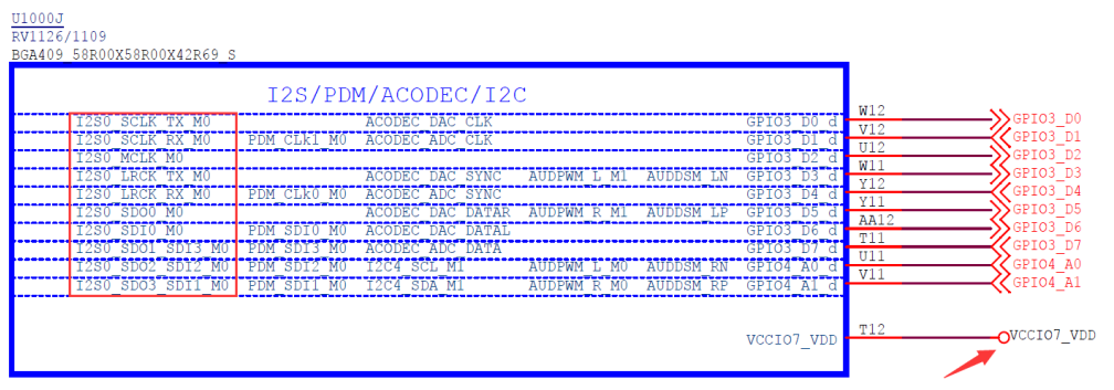
Figure 3-1 I2S IO power supply
The configuration of the corresponding power domain in the DTS is set to 1.8v, as shown below:
&pmu_io_domains {
        status = "okay";
        ...
        vccio7-supply = <&vcc_1v8>;
};
Warning: If the hardware power supply and software configuration are inconsistent, it may cause functional abnormalities, chip damage, and other risks.
3.1.2 Oscilloscope
Using an oscilloscope to measure hardware signals such as clock and data is important for debugging. It is necessary to measure the clock frequency, amplitude, duty cycle, jitter, etc. to confirm whether they comply with protocol specifications. For example, if the working voltage is 3.3V but the actual clock signal is only 2V, it may be caused by an external device pulling down the signal, a short circuit to ground, or incorrect software voltage configuration. It is also important to capture the clock and data signals and analyze them with specific data patterns to confirm if they are correct. A logic analyzer can also be used for this purpose. Trigger mode can be used to capture the problem scene, such as whether there is jitter or glitches in the CLK signal during audio dropouts.
3.1.3 Signal Generator
Signal generators can be used to generate different waveforms such as square waves, triangular waves, and sine waves. In the context of ADC testing, a signal generator can be used to produce a known input signal, such as a sine wave, which can then be fed into the ADC. The output of the ADC can then be compared to the input signal to evaluate the ADC’s distortion level and accuracy.
3.1.4 AP Analyzer
CODEC performance analyzer is used to test and analyze various performance parameters of an analog-to- digital or digital-to-analog converter (ADC/DAC) in a CODEC system. It can be used to test the digital interface signals and measure the analog signal parameters, such as signal-to-noise ratio (SNR), total harmonic distortion (THD), dynamic range, and other performance metrics. With this tool, engineers can identify any issues with CODEC performance and optimize the system accordingly.
3.2 Debug Commands
3.2.1 procfs
Confirm that the sound card has been successfully registered, you can check the /proc filesystem.
You can navigate to the /proc/asound directory and check the contents of the cards file. The cards file contains a list of all the registered sound cards on the system.
You can use the following command to view the contents of the cards file:
# cat /proc/asound/cards
 0 [rockchiprk809co]: rockchip_rk809- - rockchip,rk809-codec
                      rockchip,rk809-codec
 7 [Loopback       ]: Loopback - Loopback
                      Loopback 1
# ls /dev/snd/
by-path    controlC7  pcmC0D0p  pcmC7D0p  pcmC7D1p
controlC0  pcmC0D0c   pcmC7D0c  pcmC7D1c  timer
If the sound card has been successfully registered, you should see its name and number listed in the output.
3.2.2 clk summary
Query the audio clock to make sure it is set correctly
Example: Query the frequency of the i2s0 mclk and its corresponding PLL, result: the mclk is 12288000 Hz, and the source is cpll
# cat /sys/kernel/debug/clk/clk_summary | egrep "i2s0|pll"
pll_cpll                          1        1        0   500000000
  cpll                            5       10        0   500000000
    mclk_i2s0_rx_div              0        0        0   500000000
      mclk_i2s0_rx_fracdiv        0        0        0    12288000
        mclk_i2s0_rx_mux          0        0        0    12288000
          mclk_i2s0_rx            0        0        0    12288000
    mclk_i2s0_tx_div              1        1        0   500000000
      mclk_i2s0_tx_fracdiv        1        1        0    12288000
        mclk_i2s0_tx_mux          1        1        0    12288000
          mclk_i2s0_tx            1        1        0    12288000
            mclk_i2s0_tx_out2io   2        2        0    12288000
3.2.3 Register
3.2.3.1 io command
You can use the “io” command to view or modify registers (suitable for SOC register query) and confirm the configuration and working status with the chip manual.
# cat /proc/iomem | grep i2s
ff800000-ff800fff : i2s@ff800000
#
# io -4 -l 0x40 0xff800000
ff800000:  7200000f 004e000f 10003f3f 00000010
ff800010:  000f0110 01f00000 00000000 00000003
ff800020:  00000000 00000000 00000000 0000001f
ff800030:  00003eff 00003eff 00000303 20150001
3.2.3.2 regmap
View registers through the regmap node (read-only).
# ls /sys/kernel/debug/regmap/
0-0020-rk817-codec
ff800000.i2s
...
# cat /sys/kernel/debug/regmap/0-0020-rk817-codec/registers
12: 03
13: f4
14: 00
15: ff
16: 00
17: 40
18: 48
19: 00
1a: 00
1b: ff
1c: 00
1d: 00
1e: 02
1f: 00
...
Note: The regmap is based on a cache mechanism. If the register is directly modified through the io command, the regmap node will not reflect the updated register unless the driver sets the register type to volatile or disables the regmap cache.
Example: Disable regmap cache and obtain the correct register value.
# cd /sys/kernel/debug/regmap/ff800000.i2s/
# cat registers /* dump register by regmap */
00: 7200000f
04: 004e000f
08: 10003f3f
0c: XXXXXXXX
10: 000f0010
14: 01f00000
18: XXXXXXXX
1c: 00000000
20: XXXXXXXX
24: XXXXXXXX
2c: XXXXXXXX
30: 00003eff
34: 00003eff
38: 00000303
# io -4 0xff800000 0x0  /* set 0xff800000 to 0 */
# io -4 -l 0x40 0xff800000  /* dump to check value of 0xff800000, now it's 0 */
ff800000:  00000000 004e000f 10003f3f 00000000
ff800010:  000f0010 01f00000 00000000 00000000
ff800020:  00000000 00000000 00000000 00000000
ff800030:  00003eff 00003eff 00000303 20150001
# cat registers /* dump register by regmap */
00: 7200000f    /* it's still old value */04: 004e000f
08: 10003f3f
0c: XXXXXXXX
10: 000f0010
14: 01f00000
18: XXXXXXXX
1c: 00000000
20: XXXXXXXX
24: XXXXXXXX
2c: XXXXXXXX
30: 00003eff
34: 00003eff
38: 00000303
# echo N > cache_only
[148833.374641] rockchip-i2s-tdm ff800000.i2s: debugfs cache_only=N forced: syncing cache
# echo Y > cache_bypass
[148834.760274] rockchip-i2s-tdm ff800000.i2s: debugfs cache_bypass=Y forced
# cat registers /* dump again, now it's correct */
00: 00000000
04: 004e000f
08: 10003f3f
0c: 00000000
10: 000f0010
14: 01f00000
18: 00000000
1c: 00000000
20: 00000000
24: 00000000
2c: 00000000
30: 00003eff
34: 00003eff
38: 00000303
3.2.3.3 i2c-tools
View or modify the codec register (suitable for i2c type codec devices) through the i2c tool, and confirm the configuration and working status with the codec manual.
3.2.3.3.1 i2cdetect
Detect devices on the i2c bus
Usage: i2cdetect [-y] [-a] [-q|-r] I2CBUS [FIRST LAST]
       i2cdetect -F I2CBUS
       i2cdetect -l
  I2CBUS is an integer or an I2C bus name
  If provided, FIRST and LAST limit the probing range.
Example: Querying devices on the i2c0 bus
# i2cdetect -y 0
     0  1  2  3  4  5  6  7  8  9  a  b  c  d  e  f
00:          -- -- -- -- -- -- -- -- -- -- -- -- --10: -- -- -- -- -- -- -- -- -- -- -- -- -- -- -- --20: UU -- -- -- -- -- -- -- -- -- -- -- -- -- -- --30: -- -- -- -- -- -- -- -- -- -- -- -- -- -- -- --40: -- -- -- -- -- -- -- -- -- -- -- -- -- -- -- --50: -- -- -- -- -- -- -- -- -- -- -- -- -- -- -- --60: -- -- -- -- -- -- -- -- -- -- -- -- -- -- -- --70: -- -- -- -- -- -- -- --
3.2.3.3.2 i2cdump
dump all registers of the device
Usage: i2cdump [-f] [-y] [-r first-last] I2CBUS ADDRESS [MODE [BANK [BANKREG]]]
  I2CBUS is an integer or an I2C bus name
  ADDRESS is an integer (0x03 - 0x77)
  MODE is one of:
    b (byte, default)
    w (word)
    W (word on even register addresses)
    s (SMBus block)
    i (I2C block)
    c (consecutive byte)
    Append p for SMBus PEC
Example: Query the registers of rk817 (device address: 0x20) under the i2c0 bus, where 0x12 ~ 0x4f are codec registers.
# i2cdump -f -y 0 0x20 b
     0  1  2  3  4  5  6  7  8  9  a  b  c  d  e  f
00: 03 35 18 10 08 17 04 00 00 00 01 01 00 80 02 00
10: 00 00 03 f4 00 ff 00 40 48 00 00 ff 00 00 02 00
20: 00 00 00 00 ff 00 00 1f 00 99 00 00 00 00 00 03
30: 04 03 03 00 a5 02 00 00 11 03 03 00 00 e0 0f 09
40: a5 7f 04 58 2d 0c a5 00 00 00 00 0f 20 00 0f 88
50: 8c 00 01 00 01 b0 44 1e 00 60 16 6a 16 6a ff f8
60: ff f8 00 00 00 00 00 00 00 00 00 16 66 01 d7 00
70: 00 00 00 00 ff ed d6 58 16 6a ff f9 00 00 00 00
80: 00 00 00 00 00 00 00 00 00 00 00 00 00 00 00 00
90: 60 81 d5 7f fb df ca 81 d2 ff 00 00 00 00 00 00
a0: 00 00 00 00 b8 00 00 00 00 00 00 00 00 00 00 00
b0: 00 0f 0f 0f 0f ad 0e ff ff 00 64 18 18 64 12 18
c0: 64 00 00 64 62 62 64 ff ff ff ff ff 08 08 30 30
d0: 08 08 30 30 30 30 18 14 58 58 6c 6c 6c 6c 0b 33
e0: 00 00 00 55 a2 c8 c5 40 00 ff 22 03 0a 80 94 0b
f0: c0 8c a0 40 18 10 00 86 00 dc 00 ff 00 ff 60 00
3.2.3.3.3 i2cset
Modify a single register value
Usage: i2cset [-f] [-y] [-m MASK] [-r] I2CBUS CHIP-ADDRESS DATA-ADDRESS [VALUE] ... [MODE]
  I2CBUS is an integer or an I2C bus name
  ADDRESS is an integer (0x03 - 0x77)
  MODE is one of:
    c (byte, no value)
    b (byte data, default)
    w (word data)
    i (I2C block data)
    s (SMBus block data)
    Append p for SMBus PEC
Example: Set the value of register-0x12 to 0
# i2cset -f -y -r 0 0x20 0x12 0x0 b
Value 0x00 written, readback matched
3.2.3.3.4 i2cget
Query a single register value
Usage: i2cget [-f] [-y] I2CBUS CHIP-ADDRESS [DATA-ADDRESS [MODE]]
  I2CBUS is an integer or an I2C bus name
  ADDRESS is an integer (0x03 - 0x77)
  MODE is one of:
    b (read byte data, default)
    w (read word data)
    c (write byte/read byte)
    Append p for SMBus PEC
Example: Get the value of register-0x12
# i2cget -f -y 0 0x20 0x12 b
0x00
For more details, please refer to: i2c-tools
3.2.4 alsa-utils
RK Linux SDK comes with alsa-utils tools by default.
3.2.4.1 aplay
Usage: aplay [OPTION]... [FILE]...
-h, --help              help
    --version           print current version
-l, --list-devices      list all soundcards and digital audio devices
-L, --list-pcms         list device names
-D, --device=NAME       select PCM by name
-q, --quiet             quiet mode
-t, --file-type TYPE    file type (voc, wav, raw or au)
-c, --channels=#        channels
-f, --format=FORMAT     sample format (case insensitive)
-r, --rate=#            sample rate
-d, --duration=#        interrupt after # seconds
-s, --samples=#         interrupt after # samples per channel
-M, --mmap              mmap stream
-N, --nonblock          nonblocking mode
-F, --period-time=#     distance between interrupts is # microseconds
-B, --buffer-time=#     buffer duration is # microseconds
    --period-size=#     distance between interrupts is # frames
    --buffer-size=#     buffer duration is # frames
-A, --avail-min=#       min available space for wakeup is # microseconds
-R, --start-delay=#     delay for automatic PCM start is # microseconds
                        (relative to buffer size if <= 0)
-T, --stop-delay=#      delay for automatic PCM stop is # microseconds from xrun
-v, --verbose           show PCM structure and setup (accumulative)
-V, --vumeter=TYPE      enable VU meter (TYPE: mono or stereo)
-I, --separate-channels one file for each channel
-i, --interactive       allow interactive operation from stdin
-m, --chmap=ch1,ch2,..  Give the channel map to override or follow
    --disable-resample  disable automatic rate resample
    --disable-channels  disable automatic channel conversions
    --disable-format    disable automatic format conversions
    --disable-softvol   disable software volume control (softvol)
    --test-position     test ring buffer position
    --test-coef=#       test coefficient for ring buffer position (default 8)
                        expression for validation is: coef * (buffer_size / 2)
    --test-nowait       do not wait for ring buffer - eats whole CPU
    --max-file-time=#   start another output file when the old file has recorded
                        for this many seconds
    --process-id-file   write the process ID here
    --use-strftime      apply the strftime facility to the output file name
    --dump-hw-params    dump hw_params of the device
    --fatal-errors      treat all errors as fatal
Example: Play mute data with 48kHz sample rate, 2 channels, and 16 bits through sound card 0
# aplay -D hw:0,0 --period-size=1024 --buffer-size=4096 -r 48000 -c 2 -f s16_le /dev/zero
3.2.4.2 arecord
Usage: arecord [OPTION]... [FILE]...
-h, --help              help
    --version           print current version
-l, --list-devices      list all soundcards and digital audio devices
-L, --list-pcms         list device names
-D, --device=NAME       select PCM by name
-q, --quiet             quiet mode
-t, --file-type TYPE    file type (voc, wav, raw or au)
-c, --channels=#        channels
-f, --format=FORMAT     sample format (case insensitive)
-r, --rate=#            sample rate
-d, --duration=#        interrupt after # seconds
-s, --samples=#         interrupt after # samples per channel
-M, --mmap              mmap stream
-N, --nonblock          nonblocking mode
-F, --period-time=#     distance between interrupts is # microseconds
-B, --buffer-time=#     buffer duration is # microseconds
    --period-size=#     distance between interrupts is # frames
    --buffer-size=#     buffer duration is # frames
-A, --avail-min=#       min available space for wakeup is # microseconds
-R, --start-delay=#     delay for automatic PCM start is # microseconds
                        (relative to buffer size if <= 0)
-T, --stop-delay=#      delay for automatic PCM stop is # microseconds from xrun
-v, --verbose           show PCM structure and setup (accumulative)
-V, --vumeter=TYPE      enable VU meter (TYPE: mono or stereo)
-I, --separate-channels one file for each channel
-i, --interactive       allow interactive operation from stdin
-m, --chmap=ch1,ch2,..  Give the channel map to override or follow
    --disable-resample  disable automatic rate resample
    --disable-channels  disable automatic channel conversions
    --disable-format    disable automatic format conversions
    --disable-softvol   disable software volume control (softvol)
    --test-position     test ring buffer position
    --test-coef=#       test coefficient for ring buffer position (default 8)
                        expression for validation is: coef * (buffer_size / 2)
    --test-nowait       do not wait for ring buffer - eats whole CPU
    --max-file-time=#   start another output file when the old file has recorded
                        for this many seconds
    --process-id-file   write the process ID here
    --use-strftime      apply the strftime facility to the output file name
    --dump-hw-params    dump hw_params of the device
    --fatal-errors      treat all errors as fatal
Example: Record audio with 16kHz sample rate, 8 channels and 32 bits through sound card 0
# arecord -D hw:0,0 --period-size=1024 --buffer-size=4096 -r 16000 -c 8 -f s32_le r.wav
3.2.4.3 arecord | aplay
The two can be connected through a pipeline to achieve a loopback function, which is convenient for driver debugging and metric testing.
Example: sound card 0 capture -> sound card 1 playback
# arecord -D hw:0,0 --period-size=1024 --buffer-size=4096 -r 48000 -c 2 -f s16_le -t raw |
aplay -D hw:1,0 --period-size=1024 --buffer-size=4096 -r 48000 -c 2 -f s16_le -t raw
3.2.4.4 amixer
Control the internal path switches of the codec, and implement audio stream routing, volume control, etc. by referring to the audio topology diagram in the codec manual (such as Figure 3-2 RK3308 codec)
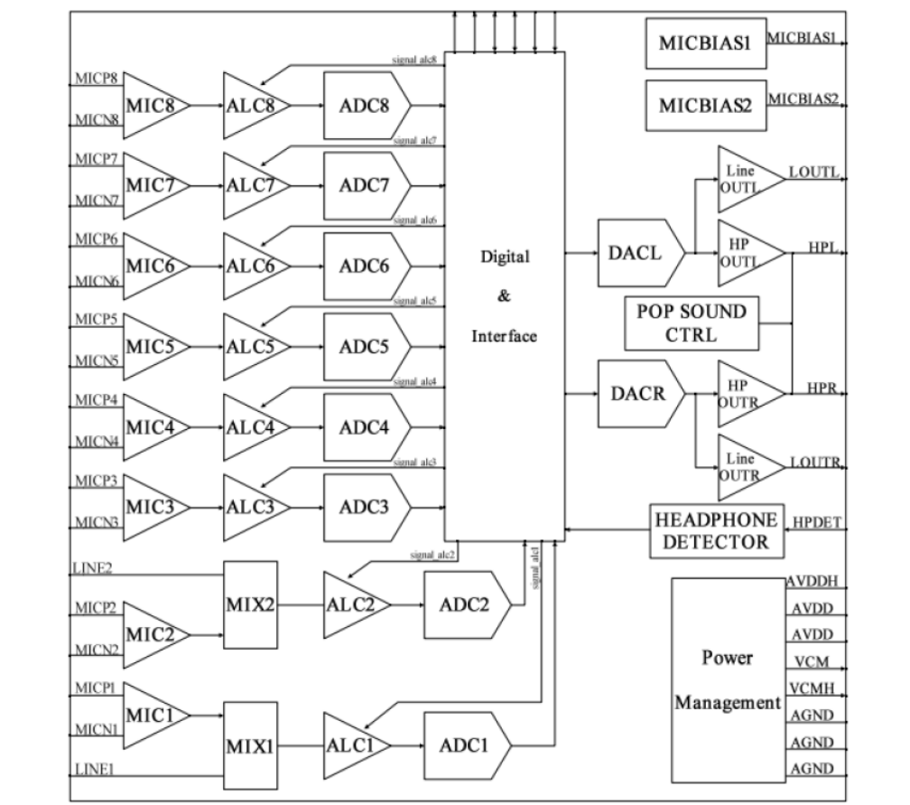
Figure 3-2 RK3308 codec
Usage: amixer <options> [command]
Available options:
  -h,--help       this help
  -c,--card N     select the card
  -D,--device N   select the device, default 'default'
  -d,--debug      debug mode
  -n,--nocheck    do not perform range checking
  -v,--version    print version of this program
  -q,--quiet      be quiet
  -i,--inactive   show also inactive controls
  -a,--abstract L select abstraction level (none or basic)
  -s,--stdin      Read and execute commands from stdin sequentially
  -R,--raw-volume Use the raw value (default)
  -M,--mapped-volume Use the mapped volume
Available commands:
  scontrols       show all mixer simple controls
  scontents       show contents of all mixer simple controls (default command)
  sset sID P      set contents for one mixer simple control
  sget sID        get contents for one mixer simple control
  controls        show all controls for given card
  contents        show contents of all controls for given card
  cset cID P      set control contents for one control
  cget cID        get control contents for one control
Example: Query the controls of the sound card and switch the playback path to SPK.
# amixer -c 0 contents
numid=1,iface=MIXER,name='Playback Path'
  ; type=ENUMERATED,access=rw------,values=1,items=11
  ; Item #0 'OFF'
  ; Item #1 'RCV'
  ; Item #2 'SPK'
  ; Item #3 'HP'
  ; Item #4 'HP_NO_MIC'
  ; Item #5 'BT'
  ; Item #6 'SPK_HP'
  ; Item #7 'RING_SPK'
  ; Item #8 'RING_HP'
  ; Item #9 'RING_HP_NO_MIC'
  ; Item #10 'RING_SPK_HP'
  : values=0
...
# amixer -c 0 cset numid=1 2
numid=1,iface=MIXER,name='Playback Path'
  ; type=ENUMERATED,access=rw------,values=1,items=11
  ; Item #0 'OFF'
  ; Item #1 'RCV'
  ; Item #2 'SPK'
  ; Item #3 'HP'
  ; Item #4 'HP_NO_MIC'
  ; Item #5 'BT'
  ; Item #6 'SPK_HP'
  ; Item #7 'RING_SPK'
  ; Item #8 'RING_HP'
  ; Item #9 'RING_HP_NO_MIC'
  ; Item #10 'RING_SPK_HP'
  : values=2
3.2.4.5 alsaloop
Support routing between any sound card
Support adaptive clock synchronization
Support self-adaptive resampling
Support mixer controls redirection
Usage: alsaloop [OPTION]...
-h,--help      help
-g,--config    configuration file (one line = one job specified)
-d,--daemonize daemonize the main process and use syslog for errors
-P,--pdevice   playback device
-C,--cdevice   capture device
-X,--pctl      playback ctl device
-Y,--cctl      capture ctl device
-l,--latency   requested latency in frames
-t,--tlatency  requested latency in usec (1/1000000sec)
-f,--format    sample format
-c,--channels  channels
-r,--rate      rate
-n,--resample  resample in alsa-lib
-A,--samplerate use converter (0=sincbest,1=sincmedium,2=sincfastest,
                               3=zerohold,4=linear)
-B,--buffer    buffer size in frames
-E,--period    period size in frames
-s,--seconds   duration of loop in seconds
-b,--nblock    non-block mode (very early process wakeup)
-S,--sync      sync mode(0=none,1=simple,2=captshift,3=playshift,4=samplerate,
                         5=auto)
-a,--slave     stream parameters slave mode (0=auto, 1=on, 2=off)
-T,--thread    thread number (-1 = create unique)
-m,--mixer  redirect mixer, argument is:
            SRC_SLAVE_ID(PLAYBACK)[@DST_SLAVE_ID(CAPTURE)]
-O,--ossmixer   rescan and redirect oss mixer, argument is:
            ALSA_ID@OSS_ID  (for example: "Master@VOLUME")
-e,--effect    apply an effect (bandpass filter sweep)
-v,--verbose   verbose mode (more -v means more verbose)
-w,--workaround use workaround (serialopen)
-U,--xrun      xrun profiling
-W,--wake      process wake timeout in ms
-z,--syslog    use syslog for errors
Recognized sample formats are: S8 U8 S16_LE S16_BE U16_LE U16_BE S24_LE S24_BE U24_LE U24_BE
S32_LE S32_BE U32_LE U32_BE FLOAT_LE FLOAT_BE FLOAT64_LE FLOAT64_BE IEC958_SUBFRAME_LE
IEC958_SUBFRAME_BE MU_LAW A_LAW IMA_ADPCM MPEG GSM SPECIAL S24_3LE S24_3BE U24_3LE U24_3BE
S20_3LE S20_3BE U20_3LE U20_3BE S18_3LE S18_3BE U18_3LE U18_3BE G723_24 G723_24_1B G723_40
G723_40_1B DSD_U8 DSD_U16_LE DSD_U32_LE DSD_U16_BE
Tip #1 (usable 500ms latency, good CPU usage, superb xrun prevention):
  alsaloop -t 500000
Tip #2 (superb 1ms latency, but heavy CPU usage):
  alsaloop -t 1000
Sync mode specification for capture to playback stream:
 0 or none       - do not touch the stream
 1 or simple     - add or remove samples to keep
                   both streams synchronized
 2 or captshift  - use driver for the capture device
                   (if supported) to compensate
                   the rate shift
 3 or playshift  - use driver for the playback device
                   (if supported) to compensate
                   the rate shift
 4 or samplerate - use samplerate library to do rate resampling
 5 or auto       - automatically selects the best method
                   in this order: captshift, playshift,
                   samplerate, simple
Example: The audio recorded by sound card 0 is played through sound card 1, and the synchronization mode use strategy 1 (adding or removing samples)
# alsaloop -C hw:0,0 -P hw:1,0 -t 10000 -A 3 -S 1 -b -v
Note:
If the clock source of sound card 0 and 1 are the same (e.g., the same OSC), there is no asynchronous cumulative error. If sound card 0 is a UAC (clock source from PC) and sound card 1 is a system sound card (clock source from device), because the clock sources are different, cumulative errors will inevitably occur over time, leading to audio dropout. In this case, software compensation (such as adding or subtracting samples) or hardware compensation (such as audio clock compensation) is required.
3.2.5 tiny-alsa
RK Android SDK comes with tiny-alsa tools by default.
3.2.5.1 tinypcminfo
Query the sampling rate, format, number of channels, etc. supported by the sound card.
Usage: tinypcminfo [-D card] [-d device]
Example:
# tinypcminfo -D 0
Info for card 0, device 0:
PCM out:
Access: 0x000009
Format0: 0x000044
Format1: 0x000010
Format Name: S16_LE, S24_LE, S32_LE
Subformat: 0x000001
Rate: min=16000Hz max=48000Hz
Channels: min=2 max=2
Sample bits: min=16 max=32
Period size: min=4 max=65536
Period count: min=2 max=4096
PCM in:
Access: 0x000009
Format0: 0x000044
Format1: 0x000010
Format Name: S16_LE, S24_LE, S32_LE
Subformat: 0x000001
Rate: min=16000Hz max=48000Hz
Channels: min=2 max=2
Sample bits: min=16 max=32
Period size: min=4 max=65536
Period count: min=2 max=4096
3.2.5.2 tinyplay
Usage: tinyplay file.wav [-D card] [-d device] [-p period_size] [-n n_periods]
Example: play 1k0 audio file
# tinyplay /sdcard/1k0.wav -D 0 -d 0 -p 1024 -n 3
Playing sample: 2 ch, 44100 hz, 32 bit
3.2.5.3 tinycap
Usage: tinycap file.wav [-D card] [-d device] [-c channels] [-r rate] [-b bits] [-p
period_size] [-n n_periods]
Example: Recording audio at 44.1k sample rate
# tinycap /sdcard/rec.wav -D 0 -d 0 –c 2 –r 44100 –b 16 –p 1024 –n 3
3.2.5.4 tinymix
Control the internal path switch of the codec, volume control, etc. The effect is equivalent to amixer
usage: tinymix [-D card]
Example: Turn on the Mono path switch
# tinymix
Mixer name: 'rockchip,rt5640-codec'
Number of controls: 123
ctl     type    num    name                                    value
0       BOOL    1      Mono Playback Switch                    Off
1       INT     2      Mono DAC Playback Volume                175 175
2       BOOL    2      Speaker Channel Switch                  Off Off
3       INT     2      Speaker Playback Volume                 31 31
4       BOOL    2      HP Channel Switch                       Off Off
...
# tinymix "Mono Playback Switch" 1
Mono Playback Switch: On
3.2.6 xrun profiling
In the context of audio processing, an xrun is an error condition that occurs when the audio data flow is interrupted or disrupted, leading to a loss of synchronization between the audio output and input. There are two types of xrun: underruns and overruns.
Underruns occur when the audio buffer is not filled with data in time for the audio device to play it back, resulting in a gap or silence in the audio output. Overruns occur when the audio buffer is not read in time, causing the audio device to discard some of the incoming audio data.
In the Linux kernel, the ALSA (Advanced Linux Sound Architecture) framework provides support for handling xruns. ALSA provides a buffer management system to ensure a continuous flow of audio data and to prevent xruns from occurring. When an xrun occurs, ALSA generates an interrupt to notify the audio device driver that the buffer is empty or full, allowing the driver to refill or flush the buffer as needed to prevent the xrun from recurring.
To handle xruns effectively, audio device drivers should be designed to support real-time audio processing with low latency and high throughput. This involves using efficient buffering techniques, such as pre-fetching and double buffering, to ensure that audio data is always available for playback or recording. Additionally, audio device drivers should be optimized to minimize the latency of audio data transmission, and should implement error handling routines to recover from xruns as quickly as possible.
3.2.6.1 xrun kmsg
- Enable XRUN CONFIG
CONFIG_SND_DEBUG
CONFIG_SND_PCM_XRUN_DEBUG
CONFIG_SND_VERBOSE_PROCFS
The xrun debugging switches are shown in Table 3-1 below. If you need to support all switches, just take the sum.
| Bit Value | Description |
|---|---|
| 1 | Basic debugging - show xruns in ksyslog interface |
| 2 | Dump stack - dump stack for basic debugging |
| 4 | Jiffies check - compare the position with jiffies (a sort of in-kernel monotonic clock), show what’s changed when basic debugging is enabled |
Table 3-1 xrun debugging switch
- Enable all xrun debug switches for sound card 0 playback devices
# echo 7 > /proc/asound/card0/pcm0p/xrun_debug
- When the dma ringbuffer of playback is underrun, similar log examples are as follows:
asoc-simple-card rk809-sound: XRUN: pcmC0D0p:0
CPU: 3 PID: 657 Comm: sh Not tainted 4.19.161 #509
Hardware name: Generic DT based system
[<b010f47c>] (unwind_backtrace) from [<b010b9a8>] (show_stack+0x10/0x14)
[<b010b9a8>] (show_stack) from [<b0850b58>] (dump_stack+0x90/0xa4)
[<b0850b58>] (dump_stack) from [<b06a39c4>] (__snd_pcm_xrun+0xa0/0x114)
[<b06a39c4>] (__snd_pcm_xrun) from [<b069dac4>] (snd_pcm_stop_xrun+0x64/0x68)
[<b069dac4>] (snd_pcm_stop_xrun) from [<b0695c4c>](snd_info_text_entry_release+0x34/0x7c)
[<b0695c4c>] (snd_info_text_entry_release) from [<b02694a4>] (close_pdeo+0x54/0x100)
[<b02694a4>] (close_pdeo) from [<b02695c0>] (proc_reg_release+0x70/0x78)
[<b02695c0>] (proc_reg_release) from [<b0210ac8>] (__fput+0x88/0x1c4)
[<b0210ac8>] (__fput) from [<b01412d4>] (task_work_run+0x94/0xb4)
[<b01412d4>] (task_work_run) from [<b010b48c>] (do_work_pending+0xc8/0xd0)
[<b010b48c>] (do_work_pending) from [<b0101064>] (slow_work_pending+0xc/0x20)
3.2.6.2 xrun ftrace
In addition to kernel log debugging information, xrun’s trace event provides more detailed debugging information, such as hwptr and applptr. This section requires enabling kernel trace debug. The kernel trace events supported by ALSA are shown in Table 3-2
| Trace Event | Description |
|---|---|
| snd_pcm:applptr | Update APP pointer |
| snd_pcm:hw_ptr_error | DMA pointer error |
| snd_pcm:xrun | xrun |
| snd_pcm:hwptr | Update DMA pointer |
- Enable FTRACE CONFIG
CONFIG_FUNCTION_TRACER
CONFIG_FUNCTION_GRAPH_TRACER
CONFIG_STACK_TRACER
CONFIG_DYNAMIC_FTRACE
- Play audio in the background
# aplay -D hw:0,0 --period-size=128 --buffer-size=256 -r 48000 -f dat /dev/zero &
- Enabling audio trace events can analyze detailed read/write information of buffer producers and consumers, making it easier to locate issues.
# cd /sys/kernel/debug/tracing
# echo "snd_pcm:applptr" >> set_event
# echo "snd_pcm:hwptr" >> set_event
# echo "snd_pcm:xrun" >> set_event
# cat trace | head -20
...
178.109942: applptr: pcmC0D0p/sub0: prev=0, curr=128, avail=128, period=128, buf=256
178.109981: applptr: pcmC0D0p/sub0: prev=128, curr=256, avail=0, period=128, buf=256
178.110224: hwptr:   pcmC0D0p/sub0: POS: pos=24, old=0, base=0, period=128, buf=256
178.110234: applptr: pcmC0D0p/sub0: prev=256, curr=280, avail=0, period=128, buf=256
178.112441: hwptr:   pcmC0D0p/sub0: IRQ: pos=128, old=24, base=0, period=128, buf=256
178.112510: applptr: pcmC0D0p/sub0: prev=280, curr=384, avail=0, period=128, buf=256
178.112553: hwptr:   pcmC0D0p/sub0: POS: pos=136, old=128, base=0, period=128, buf=256
178.112556: applptr: pcmC0D0p/sub0: prev=384, curr=392, avail=0, period=128, buf=256
178.115176: hwptr:   pcmC0D0p/sub0: IRQ: pos=0, old=136, base=0, period=128, buf=256
178.115270: applptr: pcmC0D0p/sub0: prev=392, curr=512, avail=0, period=128, buf=256
178.115321: hwptr:   pcmC0D0p/sub0: POS: pos=8, old=256, base=256, period=128, buf=256
178.115327: applptr: pcmC0D0p/sub0: prev=512, curr=520, avail=0, period=128, buf=256
For more details, please refer to: kernel/Documentation/trace/*
3.2.6.3 trace-cmd
trace-cmd is the front-end application of ftrace, which simplifies the operation steps of ftrace , as shown in the following example:
# trace-cmd record -e snd_pcm:hwptr -e snd_pcm:applptr -e snd_pcm:xrun
# trace-cmd report
For more details, please refer to: trace-cmd
3.2.6.4 KernelShark
KernelShark is the front-end application of trace-cmd , which graphically presents the data of trace-cmd . Please refer to: KernelShark
3.3 PC Tools
Audacity and Audition are both audio analysis and processing tools for the PC platform, which can be used to analyze audio problems such as dropouts, noise, distortion, and constant frequency interference.
4. FAQ
4.1 Audio interface support
Please refer to Rockchip Audio Features and the chip datasheet.
4.2 Failed to register sound cards
Confirm that the sound card driver configuration is compiled into the system according to Example of adding a sound card
According to kmsg to locate problem: DAI, CODEC or Machine, for example, the following log indicates that DAI is not registered
[ 0.584114] rk-multicodecs vad-sound: ASoC: CPU DAI (null) not registered
To check if it is DAI fail: When the DMA channel resources are insufficient, the DAI registration fails, close other modules that use DMA, and confirm again
To check if it is CODEC fail: use Multimeter and Oscilloscope to measure CODEC voltage and clock, meanwhile confirm whether i2c device communication is normal with i2c-tools .
4.3 Playback has no sound
Confirm that the audio source is not a muted file.
Use aplay or tinyplay to play, determine whether the problem occurs in userspace or kernel.
Waiting for more than 10 seconds during playback to determine if it is an I/O error problem caused by timeout.
Use amixer or tinymix to check whether the internal DAC path of the CODEC is turned on and whether the volume is muted.
Check the configuration of register, and confirm whether the configuration is correct with the chip manual or CODEC manual: IOMUX, DAI, CODEC.
Use Multimeter and Oscilloscope to measure voltage, clock, data. Confirm the voltage, the clock is normal, and there is a waveform on the data line; measure whether the analog output signal at the near end of the CODEC is normal, measure the level of the gpio enabled by the PA, and locate the problem step by step.
4.4 Playback Distortion
Use aplay or tinyplay to play 1k0 audio files.
Adjust the volume to see if distortion is related to volume level.
Use oscilloscope to check the CODEC output signal for clipping or other distortion phenomena. Check if the clock of the CODEC or input source is stable.
Use Multimeter to check if the power supply is normal and ensure it meets the power specifications described in the chip manual.
Adjust the DMA buffer’s cycle count and buffer size to see if there is any improvement.
Step-by-step to inspect nodes that may contribute to the distortion.
4.5 Record has no Sound
Generate a 1kHz waveform signal using Signal Generator and then fed into the CODEC.
Use arecord or tinycap to record, and locate whether the problem occurs in userspace or kernel.
Waiting for more than 10 seconds during capture to determine if it is an I/O error problem caused by timeout.
Use amixer or tinymix to check whether the CODEC’s internal ADC path is turned on and whether the volume is muted
Check the configuration of Register, and confirm whether the configuration is correct with the chip manual or CODEC manual: IOMUX, DAI, CODEC.
Use Multimeter and Oscilloscope to measure voltage, clock, data. Confirm the voltage, the clock is normal, and there is a waveform on the data line; measure whether the analog input signal near the CODEC is normal, and locate the problem by level.
4.6 Record Distortion
Generate a 1kHz waveform signal using Signal Generator and then fed into the CODEC.
Record with arecord or tinycap, output data with loopback, measure with Oscilloscope; or analyze with PC Tool.
Adjust the digital or analog gain, observe the loopback waveform, and compare the measured data to the test data to see if they match.
Step-by-step to inspect nodes that may contribute to the distortion.
4.7 Excessive or insufficient playback rate
Check clk summary to confirm if the clocks (MCLK, BCLK, LRCK) are accurate.
Use Oscilloscope to confirm that the clock signal is accurate.
Use PC Tool to record the output signal, and confirm if there is data loss or addition.
Use the logic analyzer to dump the chip output data to confirm if there is data loss or addition.
4.8 Regular dropouts
Regular dropout issues usually occur in heterogeneous systems, such as UAC application scenarios, BT voice application scenarios, network audio streaming, etc.
The fundamental reason is that the clock is asynchronous, and accumulated errors occur over time. This type of problem can be solved by Audio Clock Compensation.
Abnormal processing of buffer boundaries can also cause regular dropouts and noise. The problem can be analyzed through xrun profiling.
4.9 Noise
There are many reasons for noise, and some commonly used methods for locating noise are as follows:
Confirm whether the clock signal is accurate and whether the jitter is too large. For example, for HDA audio, the jitter should be less than 0.5 ns.
Confirm whether there are glitches on the clock signal, especially within the effective value judgment range of the edge. If glitches occur, they will be recognized by the chip as the clock, causing timing problems. The IO on the RK platform has a Schmitt trigger function (please refer to the chip manual for support, such as RV1126), which can effectively filter out glitches and solve the noise problem caused by random glitches.
Confirm the power supply and ground of the CODEC. The CODEC is sensitive to power supply noise, and any noise coupled into the power supply or ground will cause the CODEC’s performance to degrade, increase the noise floor, and cause noise.
Use differential circuits in the hardware to suppress common-mode noise.
Check the hardware PCB layout and investigate the source of the noise.
4.10 XRUN
For kernel xrun, refer to the xrun profiling section and list other profiling points as follows:
Use multi-threaded programming on the application side, separate the read/write threads from the audio processing threads, and ensure that data interaction with the kernel is not interrupted.
System scheduling issues can be analyzed through systrace or ftrace.
Storage IO blocking may cause data reading to be blocked. Playing a RAM device file (such as /dev/zero)
can help determine if this is the case. Check if the clock is accurate, which may cause excessive data consumption. Refer to the Excessive or insufficient playback rate, Regular dropouts
4.11 I/O error
When there is no response after playing or recording for more than 10 seconds, the kernel log prints: playback/capture write error (DMA or IRQ trouble?) .
Check the DAI controller FIFO COUNT register using Register,to see if counting has stopped.
Check if the DMA interrupt is updated using procfs: cat /proc/interrupts | grep dma .
Check if the DMA controller channel status register (offset address: 0x100) is abnormally stopped using Register.
When the DAI works as a slave, ensure that the external device clock continuously provides during the DAI’s entire lifecycle. If this cannot be guaranteed, keep it always on.